Crack Self-healing Behavior of Cementitious Composites Incorporating Various Mineral Admixtures
←
→
Page content transcription
If your browser does not render page correctly, please read the page content below
Journal of Advanced Concrete Technology Vol. 8, No. 2, 171-186, June 2010 / Copyright © 2010 Japan Concrete Institute 171
Scientific paper
Crack Self-healing Behavior of Cementitious Composites Incorporating
Various Mineral Admixtures
Tae-Ho Ahn1 and Toshiharu Kishi2
Received 16 February 2010, accepted 6 May 2010
Abstract
This study aims to develop and apply self-healing concrete as a new method for crack control and enhanced service life
in concrete structure. This concept is one of the maintenance-free methods which, apart from saving direct costs for
maintenance and repair, reduces the indirect costs – a saving generally welcomed by contractors. In this research, the
self-healing phenomenon of autogenous healing concrete using geo-materials for practical industrial application was
investigated. Moreover, a self-healing concrete was fabricated by ready-mixed car in a ready-mixed concrete factory,
then used for the construction of artificial water-retaining structures and actual tunnel structures. The results show that
the crack of concrete was significantly self-healed up to 28 days re-curing. Crack-width of 0.15mm was self-healed af-
ter re-curing for 3 days and the crack width decreased from 0.22 mm to 0.16 mm after re-curing for 7 days. Furthermore,
it was almost completely self-healed at 33 days. It was founded that this phenomenon occurred mainly due to the swell-
ing effect, expansion effect and re-crystallization. From these results, it is considered that the utilization of appropriate
dosages of geo-materials has a high potential for one of new repairing methods of cracked concrete under the water
leakage of underground civil infrastructure such as tunnels.
1. Introduction estimated at $5.2 billion. Comprehensive life cycle
analyses indicate that indirect costs due to traffic jams
The serviceability limit of concrete structures is primar- and associated loss of productivity are more than 10
ily governed by the extent of damage. Cracks, one of times the direct cost of maintenance and repair (Breugel
various types of damage, play an important role in the 2007). Especially, the average age of U.S. bridges is 42
serviceability limit. However, if it were possible to year, so they were deemed either structurally deficient
know the reason for differing behavior of concrete or functionally obsolete last year by the U.S. Depart-
structures exposed to largely similar conditions, we ment of Transportation. In March 2009, it is report that
might have the key for designing high-durability struc- the American Society of Civil Engineers gave U.S. in-
tures with low or negligible maintenance and repair frastructure a grade of “D” reflecting delayed mainte-
costs (Breugel 2007). Furthermore, the serviceability nance and chronic underfunding; it estimates that $2.2
limit of concrete structures by cracking might be over- trillion is needed over the next five years to bring that
come by crack control methodologies; the enhanced grade up to a grade of “B” (Broek 2009).
service life of concrete structures would reduce the de- For the United Kingdom, repair and maintenance ac-
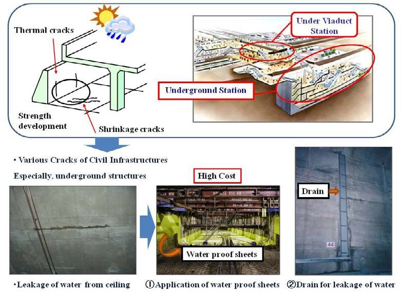
mand for crack maintenance and repair. In particular, the counts for almost 45% of the UK’s activity in the con-
utilization of self-healing technologies has high poten- struction and building industry. In case of Netherlands,
tial as a new repair method for cracked concrete under one third of the annual budget for large civil engineering
the water leakage of underground civil infrastructure works is spent on inspection, monitoring, maintenance,
such as tunnels, as shown in Fig. 1 (Ahn et al. 2009). upgrade, and repair. In case of Japan, East Japan Rail-
Recently, many potential markets of self-healing ce- way Company reported that maintenance and repair cost
ment-based materials have been reported by civil engi- of railway bridges and tunnels are estimated at $10 bil-
neers from many different countries as follows. First, lion. In the point of this, actually, if crack self-healing
the cost for reconstruction of bridges, in USA, has been concrete can minimize cracks, we can get a longer life
estimated between $20 and $200 billion. The average and more sustainable civil infrastructures (Ahn et al.
annual maintenance cost for bridges in that country is 2007).
The performance of structures with elapse of time is
often reported with graphs like that shown in Fig. 2. In
1 general, for high durability and normal designs, increas-
Research Associate, Dept. of Human & Social Systems,
ing the volume of cracks in a structure increases the
Institute of Industrial Science, The University of Tokyo,
repair costs as shown Fig. 2(b). However, when consid-
Japan.
ering the self-healing design, if a crack occurs, it will be
E-mail:than@iis.u-tokyo.ac.jp
2 healed autogenously after minor damage, as shown Fig.
Professor, Dept. of Human & Social Systems, Institute
2 (c) and (d). This concept is one of the maintenance-
of Industrial Science, The University of Tokyo, Japan.
free methods which, apart from saving direct costs for
172                     T-H. Ahn and T. Kishi / Journal of Advanced Concrete Technology Vol. 8, No. 2, 171-186, 2010

 Fig. 1 Application concept of self-healing concrete for the water leakage of underground civil infrastructures as tunnels.

maintenance and repair, reduces the indirect costs – a                    cement grains and may be aided by carbonation, since
saving generally welcomed by contractors. Furthermore,                    the bonding material so formed contains crystals of cal-
general construction philosophy has begun to change                       cium carbonate and calcium hydroxide (Homma et al.
from [Design and Construction concept: constructor                        2009). Recently, several researchers have observed the
responsibilities for maintenance and repair of structures                 formation of cementitious products such as AFt, AFm
are limited] to [Design, Construction and Maintenance                     and CaCO3 in cracks and calcium hydroxide crystals in
concept: constructor has responsibilities including the                   air voids in cracked concrete (Kishi et al. 2007). It was
maintenance, monitoring and repair for life cycle of                      hypothesized that these hydration products had been
structures] as shown Fig. 2. This trend shows that it is                  leached and recrystallized in water that had flown
necessary for both the industrial and research fields to                  through the crack. However, although it is generally
develop concrete including self-healing crack concepts                    acknowledged that unhydrated cement grains affect the
in the near future (Breugel 2007).                                        recrystallization of cracked concrete, no detailed exami-
   Therefore, the aim of this study is to develop autoge-                 nations have been reported on the healing conditions for
nous healing concrete using various mineral admixtures                    this cementitious recrystallization. For plain concrete
for practical industrial application. Research has been                   with a normal or high water/cement ratio, which does
done on the healing of cracks in aged concrete, but it                    not have any self-healing ability, the self-healing phe-
seems that very little is known about the actual healing                  nomenon is mainly controlled by the amount of mixing
mechanism and its conditions. The mechanism is gener-                     water. Therefore, in order to give self-healing abilities to
ally attributed to the hydration of previously unhydrated                 a cementitious composite at normal or high wa-
T-H. Ahn and T. Kishi / Journal of Advanced Concrete Technology Vol. 8, No. 2, 171-186, 2010            173

ter/cement ratios, the self-healing properties of concrete                on cracked concrete and the effects of various carbon-
incorporating geo-materials as a partial cement re-                       ates for the recrystallization.
placement were investigated in terms of recrystallization                    Especially, it was investigated based on consideration
                                                                          with self-healing performance of materials and cost ef-
                                                                          fectiveness as shown Fig. 2(d), in order to apply self-
                                                                          healing concrete as a new method for crack control and
                                                                          enhanced service life in concrete structures.
                                                                             This study focused on two primary issues: (1) ex-
                                                                          perimental and analytical design of cementitious materi-
                                                                          als with self-healing capabilities, (2) development of a
                                                                          self-healing concrete using new cementitious materials
                                                                          at normal water/binder ratio [over W/B=0.45] (Ahn et al.
                                                                          2008).

                                                                          2. Experimental methods
                            (a)
                                                                          2.1 Materials
                                                                          (1) Cement
                                                                          Type I Japan Portland cement was used in all cementi-
                                                                          tious composite and concrete mixtures.

                                                                          (2) Mineral admixtures & Chemical agents
                                                                          In order to compare the self-healing capability of ce-
                                                                          mentitious composite with various compositions, min-
                                                                          eral admixtures such as expansive agent, geo-materials
                                                                          and chemical agents were used. These materials were
                                                                          prepared based on self-healing performance as reported
                                                                          in the previous research shown in Fig. 3 (Ahn, 2008).
                            (b)                                           The expansive agent, two geo-materials (A, B) and
                                                                          chemical agent used were commercial products pro-
                                                                          duced in Japan.      K type of expansive agent was used
                                                                          for this investigation. It consists of three mineral admix-
                                                                          tures, C4A3 S (hauyne), CaSO4 (anhydrite) and CaO
                                                                          (free lime). Geo-material A was used for this investiga-
                                                                          tion; It has an SiO2 content of 71.3% and an Al2O3 con-
                                                                          tent of 15.4%. It shows the XRD pattern of geo-material,
                                                                          which reveals that it is mainly SiO2 and sodium alumi-
                                                                          num silicate hydroxide [Na0.6Al4.70Si7.32O20(OH)4]. It
                                                                          also contains montmorillonite, feldspar, and quartz, and
                                                                          its swelling is mainly caused by the swelling of mont-
                            (c)                                           morillonite, which is a swelling clay mineral. This type
                                                                          of geo-material swells 15-18 times its dry size when
                                                                          wetted by water as shown in Fig. 3(b), because the
                                                                          montmorillonite mineral is a 2:1 layer consisting of an
                                                                          octahedral sheet sandwiched between two silica sheets
                                                                          as shown in Fig. 4. Chemical structure of geo-material
                                                                          B is also similar to structure of geo-material A, however,
                                                                          its chemical composition is a little bit different. In case
                                                                          of chemical agent, various types of carbonates such as
                                                                          NaHCO3, Na2CO3 and Li2CO3 (etc.) were selected to
                                                                          supply the effect of cementitious recrystallization with
                                                                          expansive agent in air voids in cracked concrete.
                            (d)
                                                                          (3) Superplasticizers
Fig. 2 (a), (b): Performance (a) and costs (b) over time                  Polycarboxylate-based superplasticizer was also used in
for normal structures (black line) and high durability de-                order to fabricate specimens. Three types of superplasti-
sign structures (red line). (c), (d): Performance (c) and                 cizer: lignin-based AE plasticizer (SP I), polycarboxy-
cost (d) over time of the structure made with self-healing                late-based superplasticizer (SP II: standard type), and
concrete (Breugel. 2007).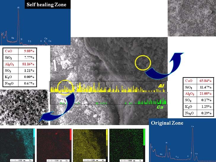
174                     T-H. Ahn and T. Kishi / Journal of Advanced Concrete Technology Vol. 8, No. 2, 171-186, 2010

                                                                           Fig. 4 Chemical structure of geo-material (Li, 1995).

                                                                          were mixed manually for 5 minutes at ambient tempera-
        (a) Expansion term (Expansive agents)                             ture. The slump test was then conducted on a small vol-
                                                                          ume of paste using the mini-slump cone. The procedure
                                                                          involves transferring the cement paste in the mini-slump
                                                                          cone, then lifting the cone smoothly and quickly. The
                                                                          area of the paste spread on an acrylic plate is measured
                                                                          and expressed in millimeters. The dosage of each super-
                                                                          plasticizer was set in the range of 0.8 – 2.50 % in order
                                                                          to obtain the initial target flow. Paste flow was meas-
           (b) Swelling term (Geo-materials)                              ured at 30 minute intervals up to 90 minutes from mix-
                                                                          ing.

                                                                          2.3 Estimation method of cementitious com-
                                                                          posites for crack healing
                                                                          Cementitious composite pastes cylinders 5Ф x 10 cm in
                                                                          size were prepared following the mini-slump test. They
        (c) Precipitated term (Chemical agents)
                                                                          were cured for 120 days and then artificially cracked in
                                                                          order to clarify the self-healing process. Crack width
Fig. 3 Design of cementitious composite materials with                    was controlled between 0.1 and 0.3 mm in consideration
self-healing capability.                                                  of the maximum tolerable crack widths according to
                                                                          construction codes. After cracking, the specimens were
                                                                          again water cured for 200 days.
polycarboxylate-based superplasticizer (SP III: slump
retention type) were used in order to clarify the effects                 2.4 Verification of self-healing capability on fab-
of each superplasticizer on the fluidity of paste and con-                ricated self-healing concrete
crete which include cementitious composites with self-                    All cementitious composite materials with self-healing
healing capability.                                                       capability [called pre-mixed products] in this research
                                                                          were manufactured in the laboratory. Table 2 and Table
2.2 Estimation method of mini-slump for fresh                             3 show the mixing proportions of concretes; a W/B ratio
properties
Table 1 shows the mix proportions of cementitious
composite materials in this research. All cementitious                     Table 1 Mix-proportions of cementitious composite
composite pastes in this research were made at a con-                      materials based on the self-healing design.
stant water/cement ratio of 0.45. 200g of cement were
                                                                             Sample       OPC      Expansive      Geo-          Chemical
used to make the cementitious paste. When the super-                                                 agent        Materials     additives
plasticizer was added, the water content of the super-                                              (CSA)         (A ,B type)
plasticizer was ignored with regards to the mixing water                         I        90%          O               O
(the solid content of the superplasticizer was around                           II        90%          O               O           O
25%). All the prepared cementitious composite pastes                            III       90%          O               O           O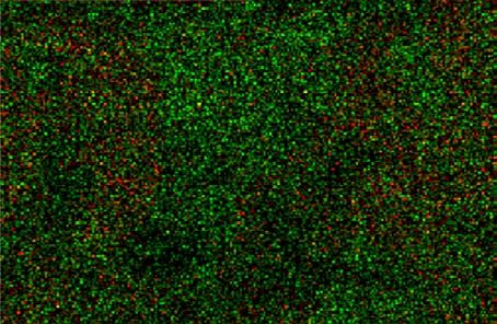
T-H. Ahn and T. Kishi / Journal of Advanced Concrete Technology Vol. 8, No. 2, 171-186, 2010             175

          Table 2 Mixing proportion of concrete.                                Thus, this method was conducted for the investigation
 Binder                          B                     370                   of fresh properties. When conducting the mini-slump
 (kg/m3)                                                                     test, the saturation point must be found for comparison
 Water/Binder                 W                        175
                                                                             between new fabricated composite materials and ordi-
 (kg/m3)                (W/B= 47.3%)                                         nary Portland cement paste (the “saturation point”: the
 Sand (kg/m3)                  S                       809                   minimum superplasticizer dosage required to achieve
 Gravel (kg/m3)                G                       920                   constant fluidity at 5 or 60 minutes) Therefore, the ef-
                                                                             fect of superplasticizer types on the fluidity was investi-
 Superplasticizer              SP
                                                                             gated first in this study.
 (% B by weight)          (1.15~1.35%)             4.26~4.99
                                                                                Figure 5 shows the effect of the addition of super-
                                                                             plasticizers on cementitious composite pastes utilizing a
             Table 3 Mix-proportions of binder.                              two component system. For two-component systems,
         Sample                           Binder                             three materials such as CSA (expansive agent), Geo-
                             OPC         Mineral admixtures                  material A and Geo-material B (two geo-materials) were
                                          EA          SHA                    added to the cement system. Water/binder ratio of all
 Plain Concrete             100%          0%           0%                    specimens was fixed at 0.45. When 0.8% of SPI was
 Expansive Concrete          90%         10%           0%                    dosed in OPC and OPC incorporating CSA, the initial
 Self-healing Concrete       93%          5%           2%                    flow was measured to be close to the target flow. In case
EA : Expansive Agent, SHA : Self-Healing Agent
                                                                             of the addition of CSA 10%, its fluidity is similar to that
                                                                             of OPC at the same dosage of SPI. However, in case of
                                                                             the addition of Geo-material A 10%, it lost its fluidity
                                                                             rapidly compared to other mineral admixtures because
of 47.3% and an S/A ratio of 46.6% were applied to all
                                                                             of water adsorption due to the swelling effect occurring
concretes. Slump flow of concrete was measured at the
                                                                             rapidly and flow could not be measured for 5 mins. This
initial point and after 30 and 60 minutes. The compres-
                                                                             shows that superplasticizers and mineral admixtures
sive strength of concrete was also measured by JIS A
                                                                             with no adsorption effect should be added in order to
1108 after 1, 3, 7, and 28 days. Self-healing concrete
                                                                             compensate for slump loss and increase the workability.
10Ф x 20 cm cylinders were prepared after conducting
                                                                             In case of the addition of Geo-material B 10%, a little
the concrete slump test.
                                                                             initial flow was lost compared to previous OPC test.
   The experiments were divided into two stages. In the
                                                                             However, there was no effect on the slump retention. In
first stage, basic properties such as concrete slump and
                                                                             other words, CSA and Geo-material B are potentially
flow, compressive strength, TSTM test and water per-
                                                                             highly useful for the co-mineral admixtures containing
meability were investigated in the laboratory. In the
                                                                             Geo-material A. Figure 6 shows the fluidity results of
second stage, they were cured for 1 month and then arti-
                                                                             cementitious composite pastes on the ternary system of
ficially cracked in order to clarify the self-healing capa-
                                                                             OPC90%+CSA5%+Geo-materials5%. As mentioned
bility and process. Crack width was controlled between
                                                                             above, the addition of Geo-material A resulted in rapid
0.1 mm and 0.3 mm according to the maximum allow-
                                                                             flow loss. Therefore, the dosage of SPI was increased to
able crack widths dictated by construction code. The
                                                                             3.0% in order to increase the fluidity. However, the ad-
specimens were then water cured for another 1 month
                                                                             dition of SPI (AE plasticizer) did not increase the
after cracking.
                                                                             workability. Increasing the dosage of SP I-3.0% resulted
                                                                             in rapid flow loss when compared to SP I-2.28%. There-
3. Results and discussion                                                    fore, the superplasticizer type was changed from SPI to
                                                                             SPII for the next stage. SPII is a polycarboxylate-based
3.1 Relationship between the fluidity of basic
                                                                             superplasticizer which is applied normally, similar to the
design materials and the amount of superplas-
                                                                             standard type. In case of the addition of SPII-3.0%, it
ticizer adsorbed
                                                                             shows similar retention effects of OPC and
In general, it is not easy to test the compatibility of a
                                                                             OPC90%+CSA10%.
particular combination of cementitious composites in-
                                                                                From these results, it can be said that at a W/B =0.45,
corporating new materials and superplasticizer in con-
                                                                             the addition of SPI in the tested ternary system was not
crete because performing concrete trial batches con-
                                                                             effective in solving the incompatibility problem. SPII
sumes time, materials, and energy. Several methods
                                                                             was more effective than SPI in fresh pastes containing
involving smaller amounts of material, which are easier
                                                                             CSA and Geo-material A according to the results of the
to implement and repeat, have been developed. These
                                                                             mini-slump test. Therefore, specimens using this mix
are generally based on studying the rheological behavior
                                                                             proportion were cured, following the previously men-
of a grout. In particular, two methods are widely used:
                                                                             tioned test methods, for 120 days in order to check the
the mini-slump method and the marsh cone method. For
                                                                             self-healing capability.
the mini-slump test, it requires very little material to
conduct and its results match well with concrete slump
results. (Jiang et al. 2000).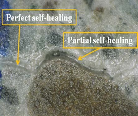
176                     T-H. Ahn and T. Kishi / Journal of Advanced Concrete Technology Vol. 8, No. 2, 171-186, 2010

                                                                                                        (a) 1 day
Fig. 5 Effect of the addition of superplasticizers on the
mini-slump of cementitious composite pastes (two-
component system or Binary system, Water/Binder ratio
= 0.45).

                                                                                                        (b) 3 days

Fig. 6 Effect of the addition of suerplasticizers on the
mini-slump of cementitious composite pastes in case of
Sample I (OPC 90% + CSA 5% + Geo-materials 5%;
three-component system, Water/Binder ratio = 0.45).

                                                                                                        (c) 7 days
3.2 Self-healing capability of cementitious
composite materials
(1) Effect s of geo-materials on the self-healing
In order to develop cementitious composite materials
with self-healing capability compared to normal cement
without self-healing capability at the normal W/C ratio,
sample I [OPC + Expansive agent + Geo-materials] was
investigated considering expansion and swelling terms
as shown Fig 3. Figure 7 shows the XRD pattern of
[OPC90%+CSA5%+Geo-materials5%] pastes by hydra-
tion time. The XRD pattern of cement pastes incorporat-
ing CSA and Geo-material A were close to that of the
two-component system incorporating expansive agent,                                                    (d) 28 days
except that the AFt phases (Ettringite) peak decreased
from 3 days and disappeared after 7 days. This indicates
                                                                          Fig. 7 Main hydration products of sample I [OPC 90% +
that these phases can be transferred from hydrated alu-                   CSA 5% + Geo-materials 5%] pastes at normal wa-
minate phases to Stratlinigte (C-A-S-H).                                  ter/binder ratio of 0.45 (the three-component system).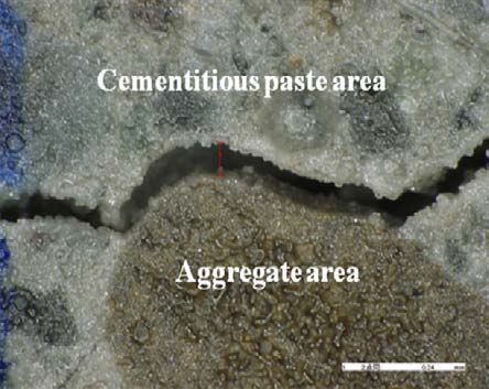
T-H. Ahn and T. Kishi / Journal of Advanced Concrete Technology Vol. 8, No. 2, 171-186, 2010 177
Figure 8 shows the healing process of the cracked
three-component system under water supply. In this case,
the crack with an initial width of 0.2 mm was almost
healed after 28 days. Rehydration products between
cracks were clearly observed after 14 days, and the
cracks self-healed perfectly even though there were
small cracks between the rehydration products after 200
days, as shown in Fig. 8 (f). (a) 3 days (b) 7 days
Figure 9 shows the entire self-healed shape of the
cracked specimen by top, side, bottom and cross-section.
It was composed of different phases between the origi-
nal and self-healing zone. Therefore, microscopy and
SEM with EDS-detector were carried out to investigate
the morphology, shape, and size of re-hydration prod-
ucts and to clarify re-crystallization.
Figure 10 shows the re-hydration products on the (c) 14 days (d) 28 days
surface of the specimen between the original and self-
healing zones in case of sample I. Figure 10 (b) shows
the X-ray map and spectra taken from rehydration prod-
ucts. It was found that the re-hydration products were
mainly composed of high alumina silicate materials as
shown in the X-ray mapping results. The self-healing
zone was composed of modified gehelite phases
(CASH) with high alumina ions compared to original (e) 40 days (f) 200 days
zone. This self-healing phenomenon seems to be related
Fig. 8 Process of Self-healing on the sample I pastes at
to the crystallization by aluminosilicate with calcium
normal water/binder ratio of 0.45 (the three-component
ion.
system).
In general, geopolymers are formed by the polymeri-
zation of individual aluminate and silicate species,
which are dissolved from their original sources at high
pH in the presence of alkali metals. These structures can
take one of three types: poly(sialate) (-Si-O-Al-O-),
poly(sialate-siloxo) (Si-O-Al-Si-O) and poly(sialate-
disiloxo) (Si-O-Al-O-Si-O-Si-O). Typical geopolymer
composition can be expressed as nM2O⋅ Al2O3⋅ xSiO2
y⋅H2O, where M is an alkali metal. In terms of chemical
composition, the major difference between geopolymers
and Portland cement is calcium.
In this research, it was found that the alkaline activa-
tion of Geo-material A in the presence of calcium hy-
droxide led to the formation of an amorphous calcium
aluminosilicate between cracks, which had the same
characteristics as a geopolymeric gel in a highly alkaline
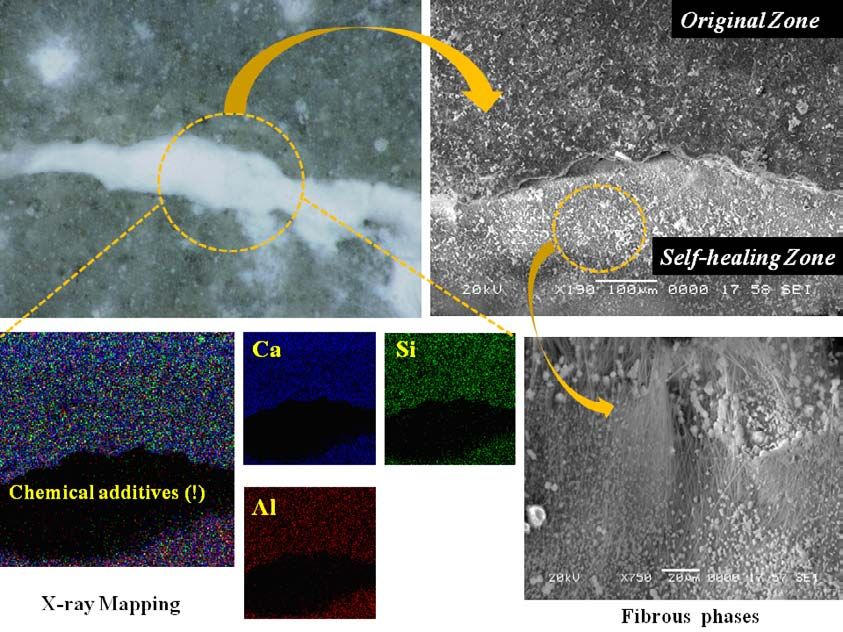
environment as shown in Fig. 11. Figure 12 shows a
detailed comparison between geopolymeric gel phase
from the self-healing area and hydrogarnet phase from
the original area by SEM images. This geopolymeric gel Fig. 9 Self-healed shape of cracked pastes according to
size was smaller than 2μm and the crack interface regions such as top, side, bottom and cross-section [in
phases of the original zone formed several hydrogarnet case of Sample I].
phases made with CSA. This indicates that hydrogarnet
phases or AFt phases, which were formed from expan-
sive agent, play an important role in crack-bridging ma-
terials. EDS analysis also revealed that most of the
modified geopolymeric gel was structured by dense
phases as compared to hydrogarent phases. self-healing concrete. However, self-healing velocity for
This seems effective for sealing against water leak- rapid water proof effect of water leakage needs to be
ages. From these results, it was concluded that applica- improved in order to apply for underground civil infra-
tion of geo-materials are desirable for the application of structures. Therefore, sample II and sample III have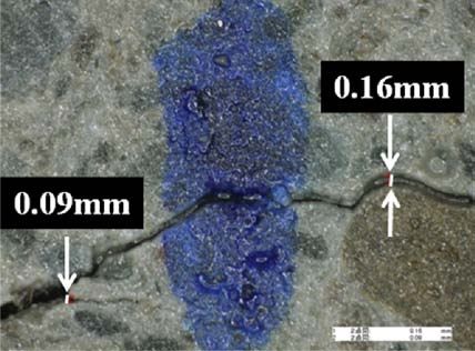
178                     T-H. Ahn and T. Kishi / Journal of Advanced Concrete Technology Vol. 8, No. 2, 171-186, 2010

                                                                             Figure 14 and Fig. 15 show SEM images, X-ray map,
                                                                          and spectra taken from re-hydration products. It was
                                                                          observed that re-hydration products were mainly com-
                                                                          posed of hydrogarnet phases (C-A-H) and calcite
                                                                          (CaCO3) phases, as shown in the X-ray spectra results.
                                                                          It was also found that re-hydration products on the sur-
                                                                          face of the specimen between the original zone and self-
                                                                          healing zone were different compared to that of sample I.
                                                                          This formation reaction seems to be related to the im-
                                                                          provement of self-healing velocity and chemical stabil-
                                                                          ity of re-hydration products. As mentioned above, the
                                                                          formation of self-healing products was faster than that
                                                                          of the previous test case due to the of formation of cal-
                                                                          cium hydroxide[Ca(OH)2 :CH]phases and C-A-H
                                                                          phases at the initial re-curing stage. However, in general,
                                                                          chemical stability of CH was lower than that of C-A-H.
                                                                          CH phases were consumed in order to form C-A-H
                                                                          phases and AFt phases as shown in Fig. 16.
(a) SEM-EDS image of self-healing area (line analysis)                       This indicates that chemical stability of re-hydration
                                                                          products can be decreased at the initial re-curing stage
                                                                          by the volume change of CH in order to transfer other
                                                                          phases. Calcite was then formed between CAH phases
                                                                          by the continuing re-hydration, shown in Fig. 17. It was
                                                                          found that this was the main mechanism of the upgrade
                                                                          design I for self-healing.
                                                                             Therefore, in order to improve the physical and
                                                                          chemical stability of these re-hydration products and
                                                                          precipitated products as calcite or calcium salts in initial
                                                                          term period, upgrade design II (sample II) was sug-
                                                                          gested and studied in detail in the following section.
(b) Comparison X-ray Mapping results between self-
healing area and original area                                            (3) Effects of chemical additives on the self-healing
                                                                          (Upgrade design II)
Fig. 10 Self-healing phenomenon of crack by crystalliza-                  The objective of upgrade design II was to consider the
tion of aluminosilicate phases on the cementitious pastes                 chemical stability as well as the improvement of self-
incorporating expansive agent and Geo-materials [Sur-                     healing velocity for the cementitious composite materi-
face Analysis of specimen].                                               als. Figure 18 shows the process of self-healing of sam-
                                                                          ple III under water supply. In this case, the crack was
                                                                          healed after re-curing for 3 days, as shown in Fig. 18
                                                                          (b). It was found that this design had greater chemical
been tested in order to improve this. These results are                   stability compared to sample II.
reported and discussed in the following section.                             Chemical additives significantly affected the formation
                                                                          of re-hydration products with high chemical stability as
(2) Effects of chemical additives on the self-healing                     compared to the previous design. Furthermore, it didn’t
(Upgrade design I)                                                        show loss of re-crystallization products compare to
Figure 13 shows the healing process of cracked parts                      sample I after re-curing 3 days as shown in Fig. 18 (c).
based on upgrade design I (sample II) under water sup-                       These rehydration products were mainly composed of
ply. In this case, the crack with an initial width of 0.2                 fibrous phases from chemical additives and calcite as
mm was self-healed after re-curing for 3 days. It was                     shown in Fig. 19. This indicates that these fibrous
found that the self-healing velocity improved remarka-                    phases, which were formed from chemical additives,
bly by re-crystallization. However, its chemical stability                play an important role in crack bridging between cracks.
seemed to be weak after re-curing for 7 days, and the                     From these results, it was concluded that various com-
crack reopened as shown in Fig. 13(c).This phenome-                       posite upgrade designs are desirable for the application
non indicates that these products are sensitive to the pH                 of self-healing concrete. Premix cementitious composite
condition and the water solubility; in other words, its                   materials based on these results were prepared for con-
chemical durability should be also improved for the                       crete mixing in order to give self-healing capability.
long time durability. After 28 days re-curing, the crack                  These results are reported and discussed simply in the
closed again by formation of self-healing products.                       following section.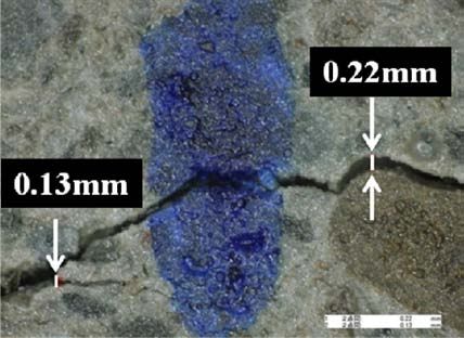
T-H. Ahn and T. Kishi / Journal of Advanced Concrete Technology Vol. 8, No. 2, 171-186, 2010                  179

Fig. 11 Comparison X-ray mapping results between self-healing area and original area [Surface Analysis of cementitious
pastes incorporating CSA and Geo-materials].

                                                                                     (a) Crack                        (b) 3 days

 (a) Comparison between original and self-healing area

                                                                                    (c) 7 days                        (d) 28 days

       (b) Hydration products of Self-healing area                                   (e) 40 days                      (f) 200 days

Fig. 12 Comparison between geopolymeric gel phase                        Fig. 13 Self-healing process of cementitious composite
from self-healing area and hydrogarnet phase from origi-                 materials based on the upgrade design I (Sample II)
nal area                                                                 [Water/Binder ratio = 0.45].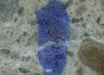
180                     T-H. Ahn and T. Kishi / Journal of Advanced Concrete Technology Vol. 8, No. 2, 171-186, 2010

                                                                          the range of 0.8 – 1.35 % in order to obtain the initial
                                                                          target slump of 21cm (target air: 4.5%). Concrete flow
                                                                          was measured up to 60 minutes at 30 minute intervals.
                                                                             When 1.20 % of SP II was dosed in self-healing con-
                                                                          crete, the initial slump value was measured close to the
                                                                          target slump value (21 cm). However, the target air re-
                                                                          quirement was not satisfied and the mix lost fluidity
                                                                          rapidly compared to normal concrete. Therefore, SP III
                                                                          was used in order to increase air and slump retention in
                                                                          the next experiment.
                                                                             Figure 20 schematically shows the fabrication proc-

                                                                                                                          A

                                                                                                           B

                                     CaO            74.57%
                                                                                            (a) CAH phases with Calcite
                                     SiO2            2.38%

                                    Al2O3           20.51%                                                                    A
                                     SO3             0.58%

                                     Na2O            0.66%

                                     MgO             1.30%

Fig. 14 Self-healed re-hydration products in crack by
hydrogarnet phases (C-A-H) and calcite phases
(CaCO3) in case of sample II.

3.3 Workability of self-healing concrete
In order to fabricate self-healing concrete using self-                                                (b) A area
healing cementitious composites, the concrete workabil-
ity test was conducted at a ready-mixed concrete factory                                                                      B
in Japan.
   All materials except premix products, which were
manufactured in the laboratory, were provided from the
ready-mixed concrete factory as shown in Fig. 20. Con-
cretes were mixed in 30~50 liter batches using materials
in the field, including cement, sand, gravel and water.
Concrete slump loss and slump flow were estimated as
functions of time. The method for testing in the field
was the same as in the laboratory.
   All concrete incorporating premixed products used a
W/B ratio of 47.3% and S/A ratio of 46.6%, and pre-
mixed products replaced ordinary Portland cement by
7%. The dosage of each superplasticizer was decided in                                                 (c) B area
T-H. Ahn and T. Kishi / Journal of Advanced Concrete Technology Vol. 8, No. 2, 171-186, 2010 181
Fig. 15 X-ray spectrum of calcite from re-hydration products between cracks in case of sample II.
Fig. 16 Formation of hydrogarnet phases and AFt phases from calcium hydroxide.
ess of self-healing concrete in ready-mixed concrete products (generally, conventional concrete is mixed for
plant. All processes were as the conventional concrete. 45 seconds).
Premixed products were handled similar to the input The concrete was then retained for around 60 min in
process of mineral admixture. A 3 m3 of concrete was the ready-mixed car in order to check the slump reten-
mixed for each artificial water-retaining structure. Mix- tion effect. After 30 and 60 minutes, slump, slump flow,
ing lasted about 60 seconds after the input of premixed and air content were again measured. Slump was main-182 T-H. Ahn and T. Kishi / Journal of Advanced Concrete Technology Vol. 8, No. 2, 171-186, 2010
(a) Crack (b) 3 days
(a) Surface morphology of self-healing products
(c) 7 days (d) 28 days
Fig. 18 Self-healing process of sample III [Upgrade de-
sign II, Water/Binder ratio of 0.45].
evolution of the expansive concrete is slightly higher
than normal concrete, and that of self-healing concrete
is slightly lower than normal concrete. The first phe-
nomenon was due to the replacement of cement by ex-
pansive agent, which has a higher hydration activity,
thus the hydration heat on the first day elevated slightly.
The second phenomenon was caused by the cement
amount, which is 10% less in self healing concrete.
(b) X-ray mapping of Ca (green) ions and Al (red) ions It is well known that expansive concrete can induce
extra expansion to compensate for shrinkage. The test
Fig. 17 Formation of CaCO3 and CAH phases in self- results showed this tendency. After 20 hours, the com-
healed area (X-ray mapping results of hydrogarnet pressive stress of the expansive concrete was 0.8MPa
phases and calcite phases). higher than that of normal concrete, whose was 1 MPa.
After temperature of specimens returned to room tem-
perature, the tensile stress of expansive concrete was
slightly lower than that of normal concrete. This is be-
tained at the target slump value of 21 centimeters and cause the extra expansion of expansive agent becomes
air was 4.5% after 1 hour. Therefore, self-healing con- stagnant after one day due to the lack of water and the
cretes incorporating premixed products with target developing stiffness of surrounding hydrated matrix.
slump, slump flow and air could be fabricated in the The restrained stress evolution of self healing concrete
actual ready-mixed concrete plant. The workability test is between these two concrete, the maximum compres-
satisfied the target slump and air requirements, as shown sive stress was 1.4MPa, and the final tensile stress was
in Fig. 21. 1.6MPa. Even though the premix added in the self-
healing concrete was composed of many composites, its
3.4 Physical properties of self-healing concrete restraint stress development is similar to that of the ex-
Cement-based materials like concrete and mortar are pansive concrete. When comparing the Young’s
quasi-brittle materials. These materials show a softening modulus, it can be seen that there is not large difference
behavior when tested in uni-axial tension. In order to among these types of binders. Based on the above, it
quantify the early age behavior of self-healing concrete could be concluded that the cracking sensitivity of self-
as compared to those of conventional and expansive healing concrete is similar to expansive concrete and
concrete, a temperature-stress testing machine (TSTM) has a better cracking resistance than normal concrete.
test was conducted. Three types of concrete – plain con- Furthermore, in case of compressive strength, it can
crete, expansive concrete (EC) and self-healing concrete be seen that SHC exhibits similar compressive strength
(SHC)–were prepared for TSTM test and their experi- to Plain as shown in Fig. 23. This means that self-
mental results are presented in Fig. 22. Under the same healing concrete also passed the minimum field re-
semi-adiabatic temperature condition, the temperature quirement for compressive strength (red line).T-H. Ahn and T. Kishi / Journal of Advanced Concrete Technology Vol. 8, No. 2, 171-186, 2010 183
Fig. 19 X-ray mapping results of fabricated fibrous phases and C-A-S-H phases [Upgrade design II, Water/Binder ratio of
0.45].
(a) Check up Ready-Mixed plant Fig. 21 Initial workability test of fabricated self-healing
concrete (Target : slump 21cm, slump flow around 40 cm
x 40 cm, Air 4.5%).
For estimating the durability of concrete structures, it
is necessary to understand the permeation of water into
concrete. Water permeability of self-healing concrete is
one of several important concrete properties for the pre-
(b) Preparation of materials (input self-healing agent)
vention of water leakage from water-retaining or under-
ground structures. In order to measure the permeability
of concrete, this research adopted an output method
which enables the measurement of the permeation di-
rectly by observing the reliability and starting point of
hydraulic divergence of permeation in concrete (Oka-
zaki, et al. 2006). Table 4 shows the water permeability
test results of self-healing concrete. Generally, the func-
(c) Fabrication of self-healing concrete tion of water permeability coefficient is as follows.
Fig. 20 Fabrication process of self-healing concrete in k=q/I (1)
the ready-mixed plant for actual application.
Where
K : water permeability coefficient (m/sec),184 T-H. Ahn and T. Kishi / Journal of Advanced Concrete Technology Vol. 8, No. 2, 171-186, 2010
Plain
Table 4 Comparison water permeability between
50
Expansive conventional concrete and self-healing concrete.
Temperature( C)
SHC Sample Time (s) V (cm/s) K (m/s)
o
40
Plain 60 0.000294 5.35E-05
30
SHC 1800 8.69E-06 1.65E-06
20
2
cement paste incorporating expansive agent made at
1 water/cement ratio of 45%. Crack width was controlled
Stress(MPa)
0 between 0.1 mm and 0.4mm to satisfy maximum toler-
-1
able crack widths. However, after 28 days curing, the
crack still remained even though the specimen was re-
-2
cured under water immersion condition for 33 days.
-3 This is because sufficient hydration occurred by the sup-
25 ply of surplus water during mixing. In other words, this
20 indicated that the specimen already lost the capability for
Modulus(GPa)
self-healing using unhydrated particles. This is similar
15
to previous results. In case of cement paste incorporat-
10 ing self-healing agent, it was also self-healed perfectly
5 after re-curing for 3 days, as shown in Fig. 24 (c). In
this case, both mineral and chemical additives were sig-
0
0 20 40 60 80 100 120 140 nificantly affected to form re-hydration products with
Time(h) high chemical stability. Moreover, in case of self-
Fig. 22 TSTM results of various concrete.
healing concrete, the crack was significantly self-healed
up to 28 days re-curing.
Figure 25 shows the healing process of cracked self-
healing concretes made at the same mixing condition as
the conventional concrete. A 0.15 millimeter crack was
self-healed after 3 days re-curing, as shown Fig. 25 (b).
After re-curing for 7 days, the crack width decreased
from 0.22 millimeters to 0.16 millimeters. Furthermore,
it was almost completely self-healed at 33 days as
shown in Fig. 25 (d).
Fig. 23 Compressive strength of self-healing concrete.
q: water flow /unit time and volume (m3/m2/sec),
i : hydraulic gradient
Water pressure was 2.0 MPa (=2 x 10⁶ N/m2) in this (a) No healing (b) No healing
research. Each specimen was cured for 28 days, and
then immersed in water again for 2 days in order to es-
timate the water permeability. The result showed that
water permeability coefficient of self-healing concrete
was significantly lower than that of conventional con-
crete. This indicates that self-healing cementitious com-
posite could be used as a mineral admixture for the seal-
ing of water leakage.
3.5 Self-healing capability of self-healing con- (c) Self-healing 3days after water immersion
crete Fig. 24 Self-healing behaviour of cementitious composite
Figure 24 (a) and Fig. 24 (b) show the healing process materials incorporating geo-materials [Water/Binder ratio
under water supply of cracked conventional paste and = 0.45].T-H. Ahn and T. Kishi / Journal of Advanced Concrete Technology Vol. 8, No. 2, 171-186, 2010 185
(a) Crack
(a) 3 days
(b) 3 days
(b) 33 days
Fig. 26 Process of self-healing on self-healing concrete
at water/binder ratio of 0.47.
This recovery appeared to include self-healing phe-
nomenon such as the swelling effect, expansion effect
and re-crystallization as mentioned above. However, in
general, it should be considered that cracked aggregate
(c) 7 days didn’t heal by itself.
Self-healing at the initial stage occurred in the cemen-
titious paste area between cracks as shown in Fig. 26,
resulting in the healing between the cementitious paste
and surface of aggregate. However, this type of crack
did not perfectly self-heal at the same time as shown in
Fig. 27. Some re-crystallization structure from the ce-
mentitious paste was deposited on the aggregate surface
or in the crack between aggregates as shown in Fig. 27.
Therefore, this indicates that cracks of these types will
take more time for self-healing.
4. Conclusions
(d) 33 days In this study, the new method of self-healing design to
Fig. 25 Process of self-healing on self-healing concrete repair cracks in cracked concrete was suggested, and the
at wter/binder ratio of 0.47. self-healing properties of cracked concrete using various
mineral admixtures were investigated.186 T-H. Ahn and T. Kishi / Journal of Advanced Concrete Technology Vol. 8, No. 2, 171-186, 2010
Acknowledgments
The author would like to thank for the advice provided
by Dr. K. Kobayashi, Mr. Y. Matsuda and Mr. S. Ikeno
at East Japan Railway Company (JR) and Assoc. Prof. A.
Hosoda at Yokohama National University in JAPAN.
References
Ahn, T. H. (2008). “Development of self-healing
concrete incorporating geo-materials : A study on
its mechanism and behavior in cracked concrete.”
Ph.D. dissertation, Department of Civil Engineering,
The University of Tokyo, Japan.
Ahn, T. H. and Kishi, T. (2007). “1st International
conference on self-healing materials.” Conference
(a) Self-healing products on aggregate surface
Review, Magazine of Korea Concrete Institute (KCI),
14(4), 82-85.
Ahn, T. H. and Kishi, T. (2008). “The effect of geo-
materials on the autogenous healing behavior of
cracked concrete.” Proceeding of 2nd ICCRRR2008,
Cape town, South Africa, 235-240.
Ahn, T. H. and Kishi, T. (2009). “New method as the
self-healing design to repair cracks in cracked
concrete.” 4th International Conference on Construc-
tion Materials : Performance, Innovations and
Structural Implications, Nagoya, Japan, 1339 -1346.
Breugel, K. V. (2007). “Is there a market for self-
healing cement-based materials?” Proceedings of the
1st International Conference on Self-Healing
(b) Diffusion of self-healing products from paste zone Materials, Delft, Netherlands, 18-20 April.
Broek, A. V. (2009). “Self-healing concrete.” Forbes
Fig. 27 Self-healing images on crack between aggregate Magazine, Nov., 46-48.
zone and paste zone of self-healing concrete. Homma, D., Mihashi, H. and Nishiwaki, T. (2009).
“Self-healing capability of fibre reinforced
cementitious composites.” Journal of Advanced
1) In order to improve the self-healing capability to Concrete Technology, 7(2), 217-228.
the cementitious system at normal water-binder ra- Jiang, S., Kim, B. G. and Aitcin, P. C. (2000). “A
tio, it is suggested that special terms such as expan- practical method to solve slump loss problem in PNS
sion term, swelling term, and precipitation term be superplasticized high-performance concrete.” Journal
considered for the design of materials and practical of Cement, Concrete and Aggregates, 22(1), 10-15.
application. Kishi, T., Ahn, T. H., Hosoda, A. and Takaoka, H.
2) Self-healing capability was significantly affected by (2007). “Self-healing behavior by cementitious
aluminosilicate materials and various modified cal- recrystallization of cracked concrete incorporating
cium composite materials. expansive agent.” Proceedings of the 1st International
3) In case of Upgrade design II (Improvement of Conference on Self-Healing Materials, Delft,
chemical stability and self-healing velocity), it was Netherlands, 18-20 April.
found that chemical and mineral additives signifi- Li, J. K. (1995). “Engineering of Inorganic materials.”
cantly affected the formation of re-hydration prod- Bando press, Korea. 72-74.
ucts with high chemical stability as well as rapid Okazaki, S. and Kishi, T. (2006). “Simulation of dead
self-healing velocity. From these concepts, some slow permeation of water into concrete based on non-
particular mix-proportions for cementitious com- newtonian fluid mechanics.” Proceedings of EASEC-
posite materials with self-healing capability were 10, Thailand,327-332.
suggested.You can also read