LV-Z Series Installation Manual - Includes: LV-Z Series Fan Coils Product Specifications
←
→
Page content transcription
If your browser does not render page correctly, please read the page content below
LV-Z Series
                   Installation Manual

                                       Includes:
                                LV-Z Series Fan Coils
                                Product Specifications

From the Manufacturers of
  Hi-Velocity SystemsTM
www.hi-velocity.com           Module LVZ - LV-Z Series Fan Coil Installation 052713
www.hi-velocity.com

                                                                      Table of Contents
Setting up your LV-Z System                                                                      Filter Maintenance......................................................... 8
   Unit Selection ................................................................ 4
                                                                                                 System Efficiency/Performance ................................... 8
   Quality Assurance ......................................................... 4
                                                                                               Installation Check List.................................... 8
Fan Coil
                                                                                               PSB Circuit Board & WEG Drive
   Placement........................................................................ 4
                                                                                                 PSB Printed Circuit Board ........................................... 9
   Hanging Straps .............................................................. 4
                                                                                                 WEG Variable Frequency Drive ................................ 10
   Unit Configuration ........................................................ 5
                                                                                                 PSB Wiring Diagram ............................................ 11-13
   Clearances....................................................................... 5
                                                                                                 PSB Extended Wiring Diagrams........................... 14-16
Water Cooling Module (WCM/WM)
                                                                                               Trouble Shooting
   Piping the WCM/WM ................................................... 6
                                                                                                 WEG Faults and causes ............................................ 17
Hot Water Coil Add-on
                                                                                                 Motor Running Too Fast ........................................... 18
   Piping the Hot Water Coil ............................................ 6
                                                                                                 Motor Running Too Slow........................................... 19
Electrical Strip Heater (ESH)
                                                                                                 Motor not Running .................................................... 20
   Wiring the ESH .............................................................. 7
                                                                                                 24v Thermostat to PSB Board .................................... 21

Return Air                                                                                       Cooling 24v Circuit Board ........................................ 22

   Return Cutout Dimensions .......................................... 7                         Heating 24v Circuit Board ........................................ 22

Return Air Base .....................................................7                           Outdoor Unit - Electrical ............................................23

Filter Rack .................................................................. 7                 Short Cycling .............................................................. 24

                                                                                               Appendix Pages
Filter ................................................................................ 7
                                                                                                 LV-Z Fan Coil Specs (Standard & Metric).................. 25
Hi-Velocity Air Purification System ... 8
                                                                                                 Quick Product Sizing Guide......................................... 26
User Guide                                                                                       Warranty.......................................................................... 27
   Indoor Air Quality......................................................... 8

                                                                                   Table of Contents
Module LVZ
                                                                     LV-Z Series Fan Coil Installation (3/28)
                                    www.hi-velocity.com

               The LV-Z System
                        By Energy Saving Products Ltd.

  All Product                                                LV-Z Fancoil
Sizing on Pg. 26                                             Specs Pg. 25

   Heating Options                                Cooling Options

          Hot Water Coil
                                                            Water Coil Module

          Electric Strip Coil

                           Other Options

           Return Air                                     Hi-Velocity Air Purification System

                   Module LVZ - LV-Z Series Fan Coil Installation (3/28)
                                                                                  © 1995-2013 Energy Saving Products Ltd.
Module LVZ
                                                                                               LV-Z Series Fan Coil Installation (4/28)
                                                            www.hi-velocity.com

    When sizing an LV-Z fan coil for a residential system, it             Fan coils are to be located indoors, however, attic, crawl
is necessary to have an accurate heat loss/gain done for the           space and garage conditions are fully acceptable. The fan coil
structure. This will ensure the proper equipment is used for           unit can be positioned in a Horizontal, Hi-Boy, or Counterflow
cooling and heating. A heat loss/gain is done for each room,           position and can be suspended from the ceiling or placed
with all rooms added together to find the total BTUH load for          directly on the floor.
the building. With the total load known, the appropriate fan coil
can be chosen from Pg. 25.
                                                                         When potential for gravity flow of the hot water exists, spring
                                                                       check valves may be needed on both the supply and return lines.

  The LV-Z fan coil is not to be used as temporary
  heating/cooling during the construction of the
  structure. If used in this capacity all warranties
  will be null and void.                                                  Please read the ENTIRE manual before
                                                                          beginning installation as this will help avoid
                                                                          mistakes that may cost time and money.
   Fan coil units specified in this section shall be designed as
a closed loop hydronic fan coil system, with published BTUH
ratings and entering water temperatures between 110°F and
190°F. The system shall allow for heating, DX or chilled water                                 Disclaimer
cooling, and heat pump applications with electric coil back-              Energy Saving Products Ltd. reserves the right to discontinue,
ups. Entering water temperature and BTUH outputs shall match           make changes to, and add improvements upon its products at
performances listed on Pg. 25.                                         any time without public notice or obligatiion. The descriptions
                                                                       and specifications contained in this manual were in effect at
                                                                       printing. Some illustrations may not be applicable to your unit.
                    Quality Assurance
                                                                                                 Fan Coils
  Fan coil units shall be a total indoor air quality system
complete with heating, cooling and air filtration, with the              The LV-Z fan coil is manufactured with a direct drive,
possibility of humidity control and fresh air make up. The fan         permanently lubricated motor that is mounted within the blower.
coil must be factory manufactured, assembled and tested.               All LV-Z fan coils are single side access. The blower assembly
  All equipment furnished under this specification shall               can be easily slid out by removing the electrical box and then
comply with the standards set out by the following standards           removing the three mounting bolts that attach the blower to the
organizations:                                                         center plate.

  CSA 		           Canadian Standards Association
                                                                                                Placement
  CE		             European Conformity
                                                                          When installing the fan coil, keep these points in mind:
  UL 		          Underwriters Laboratories
                                                                          -     Serviceability and access to the unit.
  The fan coil units shall be designed, rated, and approved by
CSA/UL.                                                                   -     Maximizing usable floor space.
                                                                          -     Location of heating/cooling source to the fan coil.
   The fan coil units shall have pre-wired controls consisting of
a 24V transformer, printed circuit board and variable frequency
drive. The circuit board shall be capable of providing heating,
cooling and constant fan. Motors shall be 3 phase with
published amp draws.
                                                                                          Hanging Strap Kit
   Sweat water connections are 3/4” for the LV-Z 1050 and
11⁄8” for the LV-Z 1750. All lines should be piped so as not
to restrict use of the access panels, filter section, or electrical       The Hanging Strap Kits are designed to suspend a horizontal
enclosure.                                                             or vertical fan coil. The nylon straps will absorb most of the
                                                                       vibration generated by the fan coil system, eliminating any
  Refer to the back of this manual for all specifications,
                                                                       sound transfer. The hanging strap kit is not recommended for
measurements, etc.
                                                                       the LV-Z-1750.

                                      Module LVZ - LV-Z Series Fan Coil Installation (4/28)
                                                                                                            © 1995-2013 Energy Saving Products Ltd.
Module LVZ
                                                                                                   LV-Z Series Fan Coil Installation (5/28)
                                                            www.hi-velocity.com
                                                                           Fig. 04 - Nylon Straps
   As previously stated, the fan coil can be positioned in many
different orientations. When placed in the Hi-Boy position,                            04a                          04b
supply air is fed from the top of the unit (Fig. 01). When placed
in the Counterflow position, supply air is fed downwards from
the unit (Fig. 02).

Fig. 01 - Hi-Boy

                                  Fig. 02 - Counter flow

                                                                                                         04c

                                                                           Secure the nylon straps to the joist or support, it may be
                                                                       necessary to install a support across the joists to properly fasten
                                                                       the Nylon Straps (Fig. 05). The Nylon Straps are always installed
                                                                       in a vertical position; they should never be installed at an angle.
                                                                       It is acceptable to put a 90º twist in the Nylon Straps (Fig. 05a),
                                                                       do not exceed 90º.
                                                                             Fig. 05 - Support might be needed

Fig. 03 - Horizontal installation
                                                                                                   Fig. 05a - 90° twist

                                                                                                    Clearances
                                                                         Clearance is only needed on the access side of the units.
                                                                       However, ensure that there is a small space between the unit
                                                                       and any other surface to prevent vibration transfer. In order to
                                                                       maintain and service the fan coil unit, the minimum clearances
                                                                       required on the access side are (Table 01).

                                                                                       Table 01 – Fan coil clearances
   Quite often, the best location for the fan coil unit is suspended    Unit                                                Inches
from the ceiling of the mechanical room, in the horizontal               LV-Z 1050*                                           22”
position (Fig. 03). This will allow for more floor space in the
room, and will minimize the duct work needed to connect to               LV-Z 1750                                            32”
the fan coil unit.                                                         *Add an additional 4” for Electric Strip Coils
                                                                                             (not available for the LV-Z 1750)
                   Fancoil Unit Only
                                                                                   Refrigerant Cooling Module
  Attach the metal flanges to the four facing corners of the
fancoil unit (Fig. 04a).                                                  Due to the size of the RCM/RPM-E Cooling Modules and the
                                                                       high volume of air produced by the LV-Z fan coil Unit, the use of
   The Nylon Straps need to be cut to the desired length (4”           the RCM/RPM-E coils with the LV-Z fan coil is not advised. For
or more). Make a 1⁄4” hole 1” from the end of the nylon strap.         refrigerant cooling needs, a third party blow through coil such as
Slide the 11⁄4” bolt into the hole of the metal flange then into       an A-Frame or N-Frame coil is suitable.
the nylon strap, secure with washer and nut. Repeat this at each
end of the nylon straps (Fig. 04b – 04c).

                                      Module LVZ - LV-Z Series Fan Coil Installation (5/28)
                                                                                                                  © 1995-2013 Energy Saving Products Ltd.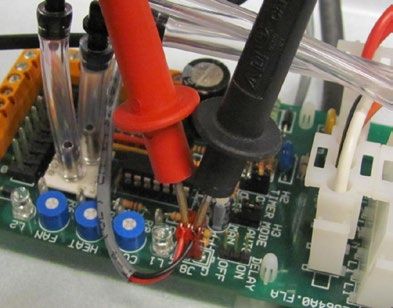
Module LVZ
                                                                                                        LV-Z Series Fan Coil Installation (6/28)
                                                             www.hi-velocity.com
                                                                        Fig. 07 - Hot Water Coil easily slides into the fan coil
          Water Coil Module (WCM/WM)
   The water coil comes as a module and must be installed in
the vertical position on the return air side of the fan coil. The
WCM/WM come supplied with two L mounting brackets for
connection to the fan coil (Fig. 06). For WCM/WM dimensional
information and sweat water connection sizes refer to the
manual shipped with the coil, also available on our website.

                Piping the WCM/WM
   When the potential for gravity flow of the hot water exists,
check valves may be needed on both the supply and return
lines. Figs. 08 and 09 give an example of this. All lines should
be piped so as not to restrict access to the front panels, filter
section, or electrical enclosure. Size your supply and return
lines according to Table 02.

              Table 02 – WCM/WM pipe sizing
    Zone BTUH              Pipe Size             Pipe Size
     Heat loss            up to 40 feet         40 – 100 feet
 0 - 35,000                    5
                                ⁄8”                  3
                                                      ⁄4”
 35,001 - 70,000               3
                                ⁄4”                  1”
                                                                        Fig. 08 - Hot water tank: Side take-offs
 70,001 - 140,000              1”                   1 1⁄4”
                                                                                             H                                   SUPPLY
     Fig. 06 - Mounting Brackets
                                                                          Domestic       C                                      RETURN
                                                                          hot water
                                                                          mixing valve
                                                                          (optional)

                                                                                                                                      Fan Coil
                                                                            Domestic
                                                                            cold water
                                                                                                  C     H

                                                                                                   Dual       SUPPLY
                                                                                                 Purpose
                                                                                                 hot water
                                                                                                   tank      RETURN

                                                                        Fig. 09 - Hot water tank: Without side take-offs
                Hot Water Coil Add-on
  The Hot Water Coil Add-on is easily installed in the LV-Z                                  H                                 SUPPLY

fan coil. With heating, condensate is not a consideration and the         Domestic                                             RETURN
                                                                                         C
coil can be mounted on the supply side of the blower (Fig. 07).           hot water
                                                                          mixing valve
   With the removal of the front panels, the coil can be slid             (optional)

in place on the supply side of the blower. For Hot Water Coil                                                                          Fan Coil
dimensional information refer to the manual shipped with the                Domestic
coil, also available on our website: www.hi-velocity.com                    cold water
                                                                                                   C    H

                                                                                                   Dual
              Piping the Hot Water Coil                                                          Purpose
                                                                                                 hot water
   Figs. 08 and 09 illustrate typical pipe runs from a dual                                        tank
purpose hot water tank to a fan coil. These drawings are only
for reference as all piping has to be run according to local code.

                                      Module LVZ - LV-Z Series Fan Coil Installation (6/28)
                                                                                                                       © 1995-2013 Energy Saving Products Ltd.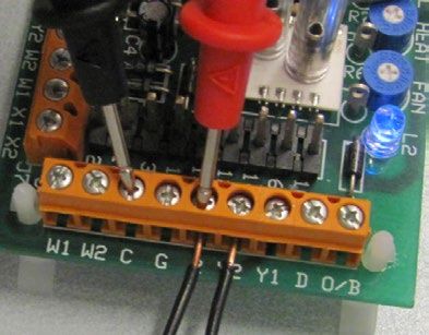
Module LVZ
                                                                                               LV-Z Series Fan Coil Installation (7/28)
                                                           www.hi-velocity.com
                                                                        Once the placement of the return has been decided, the return
            Electrical Strip Heater (ESH)                            air knockout(s) can be marked and cut (Fig. 10). The pre-
  The Electrical Strip Heater slides into the fan coil, on the       measured guide cuts on the fan coil should always be used; this
supply side of the blower (Fig. 07). Once the front access doors     will guarantee maximum airflow across the coil.
have been removed, the ESH can be slid into place.
   The ESH is labeled with a directional airflow sticker; when                     Return Air Base (Optional)
placing the ESH the sticker shall be in the direction of the air
flow. Currently, the ESH is only available for use with the LV-Z       Energy Saving Products manufactures a return air base that
1050.                                                                matches up to the fan coil units.

         Wiring the Electrical Strip Heater
                                                                       All return air bases come acoustically lined with half-inch
   Before wiring in the ESH, make sure all power sources are
                                                                     sound absorbing insulation.
disconnected. The wiring diagram is on the inside of the ESH
front panel, or refer to Pg. 10. Use only wires suitable for 167ºF
(75ºC); wires shall be sized according to local electrical code.
                                                                                 Table 04 – Return Air Base dimensions
   Use only class 2 wiring for the Control Circuit connections                             A        B         C        D
between the heater terminal 1, terminal 2 and the zone valve
                                                                       RA-70/1050       221⁄2”        213⁄4”           181⁄2”          191⁄2”
terminals. Please note, the ESH must be wired to a dedicated
breaker, separate from the fan coil.                                   RA-1750          221⁄2”        213⁄4”           241⁄2”          261⁄2”

  For Electrical Strip Heater Specifications, please refer to the                    Fig. 11 – Return Air Base
manual shipped with the coil, also available on our website:                                                                            1” Flanged in
www.hi-velocity.com                                                                                                                     for Fan Coil
                         Return Air                                                                                                     Placement

  The return air duct is not supplied with the LV-Z Fancoil
System. It is to be supplied and installed by the contractor.
The return air and fresh air make-up ducts are to be installed
according to local building code.
                    Return Air Cutout
   All LV-Z fan coils are shipped with the return air knockouts
pre-measured for multiple configurations. Table 03 contains
the pre-measured dimensions for the return air knockouts.

        Table 03 – Return Air Cutout Dimensions
Model                                   Dimensions
LV-Z 1050                               141/2” X 131/2”
LV-Z 1750                               21” X 177/8”

Fig. 10 - Return air cutout                                                          Filter Rack (Optional)
                                                                       Also available from Energy Saving Products is a 3” Filter
                                                                     Rack. Filters are 1 inch thick, 3 medium filters approximately
                                                                     14% efficient. Any after market filter may be used with the Hi-
                                                                     Velocity Filter Rack.

                                                                                  Table 05– Filter Rack dimensions
                                                                                          A              B                C               D

                                                                       LV-Z 1050          3”          18 ”
                                                                                                         1/2
                                                                                                                       19 ”
                                                                                                                          1/2
                                                                                                                                        1 ”
                                                                                                                                         1/8

                                                                       LV-Z 1750          3”          241/4”           261/2”           11/8”

                                      Module LVZ - LV-Z Series Fan Coil Installation (7/28)
                                                                                                               © 1995-2013 Energy Saving Products Ltd.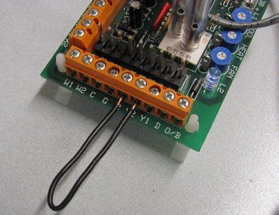
Module LVZ
                                                                                                  LV-Z Series Fan Coil Installation (8/28)
                                                               www.hi-velocity.com

        Hi-Velocity Air Purification System

                                                                                     System Efficiency/Performance

            B                                                                A big misconception that people have is that by turning off
                                                                          the air conditioning when they leave home, they save on cooling
                                                                          costs. This is not necessarily true as the system will need to run
                                                                          longer and harder when pulling the house down to temperature
                       A                 C                                after being shut off for a large amount of time. Keeping the
    Easily installed on any Hi-Velocity or existing HVAC System,          temperature within a small range when there are no loads from
 the HE PS gives consumers unsurpassed indoor air quality. The            human use will result in less overall energy consumption.
 HE PS will work at the airflow rates of the LV-Z 1050 only. For
 3 stage filtration on the LV-Z 1750, we recommend using the
 HE PS 1750. See our website for specifications.

                Table 06 –HE PS dimensions
                                  A           B            C
                                                                                         Installation Checklist
  HE PS w/ Flange               25 ’
                                   3/4
                                             17 ”
                                               3/4
                                                          10”
                                                                             Ensure that all electrical connections are tight, and that any
                                                                          packing or shipping restraints are removed from both the fan
                                                                          coil, and the outdoor unit. With the power to the condensing
                                                                          unit off, check the thermostat for normal operation and proper
                                                                          airflow from all vents. Do not run the fan coil without a filter
                                                                          in place.

                                                                             Observe the system pressures during the initial start-up and
                   LV-Z User Guide                                        charging of the system. Refer to the outdoor or indoor coil
                                                                          manufacturer’s charging guidelines. Check the voltage and amp
                Indoor Air Quality (IAQ)                                  draw of both the fan coil, and the outdoor unit. The voltages
                                                                          must be within 10% of the rating plate data. If more than 10%
   Ensure that there is always a filter in place and check every          is noted, contact your local electrical company. Check that the
month to ensure that the filter is clean. The amount of time              amp draws of both units are within the information printed on
between filter changes and cleaning will be dependant upon the            the unit rating plates.
living habits of the homeowner. With a clean air filter, you not
only have cleaner air to breathe, but you will also help maintain
unit efficiency, as well as increase the operating life of the unit.

                   Filter Maintenance

   The 1” 3 medium filters supplied by Energy Saving Products                In the event of difficulty during the start-
Ltd. can be cleaned and re-used. If the filter needs cleaning,
the system should first be shut down and the filter removed.                 up procedure, please refer to the trouble
Once out of the unit, the filter can be vacuumed on the pink
side and washed on the white side. Once the filter has been                  shooting flow charts (Pgs. 17-24) to
vacuumed, cleaned, and completely dried, it can be replaced in
the unit. Note that the pink side of the filter faces the blower and         assist you in determining the problem.
the white side towards the return air. A filter can generally be
cleaned a few times, if re-used too often it will restrict airfow.

                                         Module LVZ - LV-Z Series Fan Coil Installation (8/28)
                                                                                                               © 1995-2013 Energy Saving Products Ltd.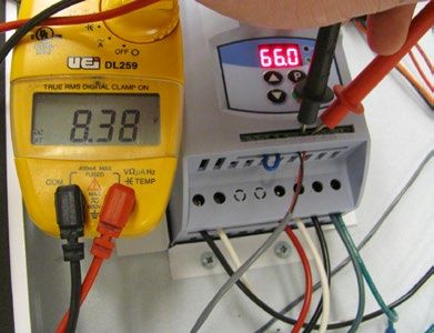
Module LVZ
LV-Z Series Fan Coil Installation (9/28)
www.hi-velocity.com
PSB Circuit Board
The LV-Z Series Fan Coil utilizes a dual function Circuit Board. This circuit board makes zoning simple and easy, eliminating
the need for by-pass dampers and dump zones. It also makes adjustment to airflow quick with the use of trim pots for direct
control.
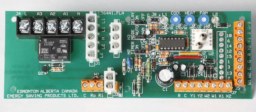
Auxiliary Relay VDC Control Fan Delay 0 - 10v Operation Mode Fan Adjustment Pressure Sensor
Terminals (Heating) Method Switch On/Off Switch DC Output Indicator Trimpots Indicator Light
T’Stat
Connections
Emergency 24v Pump Timer Condenser/Zone
Disconnect Auto-Reset on/off Switch Valve Connections
Fuse
Features:
• If you wish to have the timer cycle operate at a specific time of
• Wiring the circuit board is a quick and simple task. day, simple turn off power to the fan coil unit for ten seconds at
• Clearly labeled connections. that time and then turn the power back on.
• No additional relays typically required. • If you do not need to use the timer, move the jumper header from
• When the PSB is set to “Auto”, it allows for automatic airflow the On pins to the Off pins and it will be disabled.
adjustments, according to the static pressure of the supply air, making • Circuit board is equipped with an emergency disconnect feature.
zoning a breeze. If there’s an emergency this feature will de-energizing all fan
• “Manual” mode allows for direct speed control of the fan anywhere speeds and connected equipment.
from 0-100% capability. • For this emergency disconnect feature to be active a jumper
• Fan speeds in both functions are individually set for cooling, heating header must be remove from the pins located close to the emergency
and constant fan using the three trim pots located on the PSB. disconnect terminal strip.
• Circuit board is capable of controlling boilers, dual purpose hot • A fan delay is programmed into the circuit board. This delay will
water heaters, heat pumps, and geothermal systems, as well as our prevent the fan from starting for 20 seconds on cooling, 30 seconds
manufactured slide-in electric strip heaters (ESH). on heating, and purge for 30 seconds on shut-down. This delay
is beneficial in certain applications to give the heating or cooling
• The circuit board is also designed to send control signals to cooling equipment a “head start” before the fan turns on.
sources such as condensing units, chillers, heat pumps and geothermal
systems.
• Circuit board features an auxiliary relay with dry contacts Function:
connections, so that any applications requiring 24v, 120v, 230v or dry • Manages input power and through the use of a transformer it
contacts (boilers, hot water heaters, heat pumps & humidifiers) can be supply 24vac to additional equipment.
automatically started when there’s a call for heat.
• Organizes all thermostat inputs and prioritizes them accordingly.
• Circulator timer chip is provided to prevent water stagnation in
• Sends a 0-10vdc output to the VFD, dependent on how fast it
potable water systems and to provide pump rotor protection for water
wants the fan to run.
source heating and cooling.
Module LVZ - LV-Z Series Fan Coil Installation (9/28)
© 1995-2013 Energy Saving Products Ltd.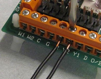
Module LVZ
                                                                                                               LV-Z Series Fan Coil Installation (10/28)
                                                                 www.hi-velocity.com

                                              WEG Variable Frequency Drive

                                                                      The LV-Z Series Fan Coil utilizes a WEG Variable Frequency Drive
                                                                      to run its 3-phase motor. The WEG VFD is a reliable and robust
                                                                      motor control that will provide many years of issue free operation.

       Features:
       •     Purposely oversized to ensure increased reliability and higher efficiencies at peak load
       •     Features inherent with VFD allows for minimum power consumption at reduced loads (
THERMOSTAT CONNECTIONS AUXILIARY HEATING RELAY JUMPER PIN SETTINGS
© 1995-2013 Energy Saving Products Ltd.
R - 24 VAC OUTPUT N - NEUTRAL H1 EMERGENCY DISCONNECT: REMOVE PIN IF WIRED TO EMERGENCY DISCONNECT
W1 - FIRST STAGE HEAT L - LINE VOLTAGE H2 TIMER: AUXILIARY RELAY TIMER (SEE NOTES)
LV-Z Series Fan Coil Installation (11/28)
W2 - SECOND STAGE HEAT A1 - AUXILIARY NORMALLY OPEN H3 MODE:
(OR SINGLE STAGE) A2 - AUXILIARY NORMALLY CLOSED AUTO - FAN SPEED MODULATES DEPENDING UPON STATIC PRESSURE
Y1 - FIRST STAGE COOLING A3 - AUXILIARY COMMON MANUAL - FAN SPEED OPERATES AT TRIM POTS SET AIR FLOW
Y2 - SECOND STAGE COOLING H4 DELAY: Y/20 SECOND, W/30 SECOND FAN DELAY.
(OR SINGLE STAGE) 24 VAC OUTPUT CONNECTIONS Y AND W 30 SECOND POST PURGE.
C - 24 VAC COMMON X1 - FREEZE STAT
G - THERMOSTAT FAN SWITCH X2 - FREEZE STAT NOTES:
Module LVZ
D - Y SPEED OVERRIDE (70% OF Y) W1 - HEATING (W1) 24 VAC OUTPUT 1) USE THERMOSTAT FAN SWITCH TO DISABLE/ENABLE CONTINUOUS FAN.
O/B - HEATPUMP REVERSING W2 - HEATING (W2) 24 VAC OUTPUT 2) ‘C’ TERMINAL ON THERMOSTAT (COMMON) IS NOT NEEDED FOR SOME THERMOSTATS
Y2 - CONDENSING UNIT 24 VAC OUTPUT CONSULT THERMOSTAT INSTRUCTIONS FOR DETAILS.
EMERGENCY DISCONNECT Y1 - CONDENSING UNIT 24 VAC OUTPUT 3) W1 AND W2 ACTIVATES AUXILIARY RELAY (A3) ON CALL AND CAN BE USED WITH A1
C - 24 VAC COMMON C - 24 VAC COMMON AND/OR A2 AS DRY CONTACTS, ARMED 24VAC FROM THE ‘R’ TERMINAL, OR ARMED
Ro - 24 VAC INPUT R - 24 VAC OUTPUT 110v FROM THE ‘L’ TERMINAL.
Ri - 24 VAC OUTPUT 4) AUXILIARY HEATING RELAY TIMER ACTIVATES CIRCUIT FOR 5 MINUTES EVERY 24
LED LIGHT INDICATORS HOURS STARTING WHEN POWER IS APPLIED TO THE UNIT.
LED 1 - GREEN LIGHT, PUMP TIMERS/ 5) LED 1: INDICATOR LIGHT FOR FAN SPEED OPERATION AND AUXILIARY RELAY
OPERATION MODE INDICATOR OPERATION. SEE MANUAL FOR LIGHT OPERATION SEQUENCE.
LV-Z Fan Coil - PSB Wiring Diagram
LED 2 - BLUE LIGHT, PRESSURE SENSOR
Module LVZ - LV-Z Series Fan Coil Installation (11/28)
POWER INPUT: 110-120/1/60 POWER INPUT: 208-240/1/60
MOTOR LEADS PLUG MOTOR LEADS PLUG
(3 PHASE) (3 PHASE)
PSB CIRCUIT BOARD Equipment PSB CIRCUIT BOARD Equipment
J4
J4
318.23 Pcbw-001sep-039 318.23 Pcbw-001sep-039
Ground Ground
G BK WH R G BK WH R
L
L
AUXILIARY RELAY
AUXILIARY RELAY
(HEATING)
(HEATING)
A3
A3
www.hi-velocity.com
110/120 VAC 110/120 VAC
A2
A2
110-120/1/60 208-240/1/60
A1
A1
PE W V U L/L1 N/L2 PE W V U L/L1 N/L2
EMERGENCY DISCONNECT
N
N
EMERGENCY DISCONNECT
L1 L1
L L
J1
L L
L2 L2 N L1 L1
J1
L2 L2 N
C Ro Ri
C Ro Ri
9 10 11 12 8 7 6 5 4 3 2 1 9 10 11 12 8 7 6 5 4 3 2 1
H1
H1
110-120v POWER CABLE Red Red
Black 208-240v POWER CABLE Black
J9
J9
G BK WH N Orange G BK WH R N Black
White White
J2
J2
L1
L2
N
Ground
N
Ground
L
0 0
WEG CONTROLLER
WEG CONTROLLER
I I
Black Orange
P P
J3
J3
H2 H3 H4 H2 H3 H4
F1
F1
TIMER MODE DELAY TIMER MODE DELAY
LINE IN ON AUTO ON Black Wire (-) LINE IN ON AUTO ON Black Wire (-)
Value Value
OFF MAN OFF OFF MAN OFF
-
-
0-10 VDC 0-10 VDC
Parameter Parameter
+
+
R
R
J8 L1
J8 L1
Red Wire (+) Red Wire (+)
LED
LED
G
G
C Y1 Y2 W2 W1 X1 X2
C Y1 Y2 W2 W1 X1 X2
R8 R8
24v OUTPUT
24v OUTPUT
COOL
COOL
C
C
R7 R7
HEAT
HEAT
VFD VFD
H
H
R6
110-120 VAC
R6
208-240 VAC
FAN
FAN
F
F
- -
U2
U2
24v / 20va 24v / 20va
LED
LED
L2
L2
TRANSFORMER TRANSFORMER
+
+
J7
J7
W1 W2 C G R Y2 Y1 D O/B W1 W2 C G R Y2 Y1 D O/B
J5
J5
TRIM POTS (COOLING, HEATING, CONSTANT FAN) TRIM POTS (COOLING, HEATING, CONSTANT FAN)
THERMOSTAT - ATMOSPHERIC PRESSURE THERMOSTAT - ATMOSPHERIC PRESSURE
+ DUCT PRESSURE + DUCT PRESSURE
FAN ADJUSTMENT TRIM POTS WHEN ADJUST TRIM POTS: ON POWER START UP, ALLOW 30 SECONDS MANUAL MODE: LED 2 WILL BE OFF, ADJUST AIR EACH OF THE FLOWS TO
FOR SYSTEM TO PRESSURIZE BEFORE MAKING ANY CHANGES. DESIRED CFM/LPS OUTPUT.
INCREASE AIR FLOW DO NOT ADJUST MORE THAN A ½ TURN AT A TIME, ALLOW 45 SECONDS * DECREASE AIR FLOW ADJUST TRIM POT COUNTER CLOCKWISE
(CLOCKWISE) BETWEEN ADJUSTMENTS FOR THE PSB TO REACH SET POINT. * INCREASE AIR FLOW ADJUST TRIM POT CLOCKWISE
DECREASE AIR FLOW AUTO MODE: LED 2 WILL SPORADICALLY FLICKER BLUE (ON/OFF) TO REFER AND COMPLETE COMMISSIONING REPORT PRIOR TO NORMAL
(COUNTER CLOCKWISE) SHOW THAT IT IS PROPERLY SENSING PRESSURE IN THE SYSTEM. OPERATION. FOR FULL DETAILS, REPORT IS AVAILABLE IN THE
* NO LIGHT INDICATES TRIM POT IS ABOVE NORMAL OPERATING INSTALLATION MANUAL OR ONLINE AT WWW.HI-VELOCITY.COM
RANGE (COUNTER CLOCKWISE DECREASE).
* SOLID LIGHT INDICATES TRIM POT IS BELOW NORMAL OPERATING MAY.9
RANGE (CLOCKWISE, INCREASE). ESP 318.23Module LVZ
LV-Z Series Fan Coil Installation (12/28)
www.hi-velocity.com
LV-Z Fan Coil - PSB Circuit Board Wiring
24 VAC Input terminals (t-stat connections):
W1: 1st stage Heating, Runs at the heating speed when 24v (R) is supplied, set by the heat trim pot.
2nd stage Heating, Runs at the heating speed when 24v (R) is supplied, set by the heat trim pot. The
difference between a W1 call and a W2 call is the output terminal that will be energized with 24v.
W2: (W1 energized on t-stat terminal strip will provide 24v to W1 on output terminal strip, W2 energized
on t-stat terminal strip will provide 24v to W2 on output terminal strip,)
C: Common
G: Constant Fan, Runs at the Constant Fan speed when 24v (R) is supplied, set by the Fan trim pot.
24 volt supply
R: (Note: As long as Transformer is connected & the Fire Disconnect/Jumper Pin Header is Present)
Y2: 2nd stage Cooling, Runs at the Cooling speed when 24v (R) is supplied, set by the Cool trim pot.
1st stage Cooling, Runs at the Cooling speed when 24v (R) is supplied, set by the Cool trim pot. The
difference between a Y1 call and a Y2 call is the output terminal that will be energized with 24v. (Y1
Y1: energized on t-stat terminal strip will provide 24v to Y1 on output terminal strip, Y2 energized on
t-stat terminal strip will provide 24v to Y2 on output terminal strip,)
D: Runs at 70% Cooling speed when 24v (R) is supplied, set by the Cool trim pot.
O/B: Dead Terminal
Fan Speed Priority Sequence (from highest to lowest): D = 1st Y = 2nd W = 3rd G=4th
24 VAC Output terminals (24v output connections):
24 volt Supply
R: (Note: As long as Transformer is connected & the Fire Disconnect/Jumper Pin Header is Present)
C: Common
Y1: 1st Stage Cooling Equipment
Y2: 2nd Stage Cooling Equipment*
W2: 24v Output to 2nd Stage Heating Equipment.
W1: 24v Output to 1st Stage Heating Equipment.
X1: Freeze Stat Connection*
X2: Freeze Stat Connection*
*Note: X1 to X2 recommended to be wired to Freeze Stat (Anti-Ice Control). For chilled water applications, a jumper between X1 to X2 must be
installed to complete the Y2 - 24V Signal to Y on Condenser.
Module LVZ - LV-Z Series Fan Coil Installation (12/28)
© 1995-2013 Energy Saving Products Ltd.Module LVZ
LV-Z Series Fan Coil Installation (13/28)
www.hi-velocity.com
LV-Z Fan Coil - PSB Circuit Board Wiring Cont’d
Emergency Disconnect:
C: Common
C: Common
Provides 24VAC to the entire PSB board. In order for “Ro” to receive power it must be connected to
terminal “Ri”. This can be done via the three pin jumper header (H1) located above the terminal strip,
Ro: a wire jumper or normally closed safety device installed between “Ro” and “Ri”. The jumper pin
header (H1) will need to be removed to activate the emergency disconnect option.
Receives 24VAC direct from the transformer. Power must then be sent to the “Ro” terminal to be
Ri: distributed throughout the rest of the PSB board.
3 Pin Jumper Terminals:
H1: Emergency Disconnect
Pump timer cycles the pump on for 5 minutes every 24 hours to prevent stagnant water. (on/off) The
H2 Timer: jumper pin header (H2) will need to be in the ON position for the timer to be active.
Switches the control method used by the PSB to control motor speed.
“Auto” uses the pressure transducer in order to modulate fan speed to maintain a constant supply
H3 Mode: pressure.
“Man” allows for direct speed control of the motor by-passing the pressure transducer. The jumper
pin header (H3) determines the control method.
Cooling/20 second, Heating/30 second fan delay, and 30 second post purge. The jumper pin header
H4 Delay: (H4) will need to be in the ON position for the delay to be active.
Auxiliary Heating Relay:
N: Neutral
L: Line Voltage
A1: Auxiliary Relay Normally Open
A2: Auxiliary Relay Normally Closed
A3: Auxiliary Relay Common
Control Signal:
J8: 0-10 Volt DC Output to VFD
Module LVZ - LV-Z Series Fan Coil Installation (13/28)
© 1995-2013 Energy Saving Products Ltd.SAMPLE AUXILIARY RELAY WIRING OPTIONS FOR HEATING (W1 OR W2)
L L L
1 Stage Cooling 1 Stage Heating 1 Stage Cooling 2 Stage Heating
A3 R A3 A3
Heatpump A2 A2 A2
HEATING MODE: REFER TO
AUXILIARY CONTACT INFORMATION A1 A1 A1
FOR W1 AND W2
N N N
C
DRY CONTACTS 24 VAC 115 VAC
RELAY WIRING RELAY WIRING RELAY WIRING
SAMPLE AUXILIARY RELAY WIRING OPTIONS FOR HEATING (1 STAGE - W2 ONLY)
DRY CONTACT T R
TO BOILER L
T C
Y1 A3
C Y C Y Y O/B R W1 Y2
A2
115v
EXTERNAL W2 CIRCULATOR
CONDENSER CONDENSER SPDT RELAY
24 VAC COIL W1 A1
ANTI-ICE W1 W2 C G R Y2 Y1 D O/B ANTI-ICE W1 W2 C G R Y2 Y1 D O/B
CONTROL CONTROL
X1
N
DRY CONTACTS AND 115 VAC X2
RELAY WIRING
W C G R Y SAMPLE AUXILIARY RELAY WIRING OPTIONS FOR HEATING
(W1 OR W2)
W C G R Y DRY CONTACT EXTERNAL
E W2 C G R Y O/B SPDT RELAY
THERMOSTAT TO BOILER
E W2 C G R Y O/B 24 VAC COIL
T T
THERMOSTAT 115 V TO
CIRCULATOR
2 Stage Cooling 1 Stage Heating 2 Stage Cooling 3 Stage Heating R
Heatpump C L
HEATING MODE: REFER TO Y1
A3
AUXILIARY CONTACT INFORMATION Y2
FOR W1 AND W2
W2 A2
ANTI-ICE
ANTI-ICE (W2) 24v OUTPUT
CONTROL
CONTROL W1 A1
www.hi-velocity.com
(W1) 24v OUTPUT
X1
N
X2
please call the technical department at Energy Saving Products Ltd. for further assistance.
W1 W2 C G R Y2 Y1 D O/B
W2 - SINGLE STAGE OR 2ND STAGE HEAT 24v, DRY CONTACTS AND 115 VAC
W1 - FIRST STAGE HEAT RELAY WIRING
C Y1 Y2 O/B R W1 C Y1 Y2 O/B R W1
FOR SINGLE STAGE OPERATION
CONDENSER CONDENSER
Module LVZ - LV-Z Series Fan Coil Installation (14/28)
USE W2 & Y2 TERMINALS
W1 W2 C G R Y2 Y1 D O/B W1 W2 C G R Y2 Y1 D O/B
R - 24 VAC OUTPUT N - NEUTRAL
W1 - FIRST STAGE HEAT L - LINE VOLTAGE
W2 - SECOND STAGE HEAT A1 - AUXILIARY NORMALLY OPEN
(OR SINGLE STAGE) A2 - AUXILIARY NORMALLY CLOSED
LV-Z Fan Coil - Extended Wiring Diagrams
Y1 - FIRST STAGE COOLING A3 - AUXILIARY COMMON
Y2 - SECOND STAGE COOLING
E W2 C G R Y2 Y1 E W2 C G R Y2 Y1 O/B (OR SINGLE STAGE) X1 - FREEZE STAT
THERMOSTAT E W2 C G R Y2 Y1 O/B C - 24 VAC COMMON X2 - FREEZE STAT
THERMOSTAT G - THERMOSTAT FAN SWITCH W1 - HEATING (W1) 24V OUTPUT
Module LVZ
D - Y SPEED OVERRIDE (70% OF Y) W2 - HEATING (W2) 24V OUTPUT
O/B - HEATPUMP REVERSING VALVE Y2 - CONDENSING UNIT (Y2) 24V OUTPUT
Y1 - CONDENSING UNIT (Y1) 24V OUTPUT
C - 24 VAC COMMON
R - 24 VAC OUTPUT
Energy Saving Products
12615-124 Street, Edmonton, AB T5L-0N8 ESP315.08
LV-Z Series Fan Coil Installation (14/28)
© 1995-2013 Energy Saving Products Ltd.
Extended wiring diagrams for the various applications the LV-Z model can be used for. If you do not find the wiring configuration you require,W1 W2 C G R Y2 Y1 D O/B
CHILLED WATER WIRING
CHILLED WATER WIRING
CHILLED WATER WIRING
Extended wiring diagrams for the various applications the LV-Z model can be used for. If you do not find the wiring configuration you require,
© 1995-2013 Energy Saving Products Ltd.
C G R Y
1 Stage Cooling 2 Stage Cooling C G R Y
1 Stage Cooling c/w chilled
1 Stage Cooling
water circulator 2 Stage Cooling c/w chilled
2 Stage Cooling
water circulator THERMOSTAT
LV-Z Series Fan Coil Installation (15/28)
c/w chilled water circulator
c/w chilledCOOLING
water circulator
COOLING
CIRCULATOR
c/w chilled water circulator
c/w chilled water circulator
COOLING
CIRCULATOR
HEATING MODE OPTIONS: REFER TO
COOLING
CIRCULATOR
CIRCULATOR
HEATING MODE OPTIONS:
COOLING
REFER TO
CIRCULATOR
COOLING
CIRCULATOR
1 Stage Cooling (Only)
AUXILIARY CONTACT INFORMATION
HEATING MODE OPTIONS: REFER TO
FOR W1 AND W2
AUXILIARY CONTACT INFORMATION
HEATING MODE OPTIONS: REFER TO
AUXILIARY CONTACT INFORMATION
AUXILIARY CONTACT INFORMATION
HEATING MODE OPTIONS: REFER TO
FOR W1 AND W2
AUXILIARY CONTACT INFORMATION
HEATING MODE OPTIONS: REFER TO
AUXILIARY CONTACT INFORMATION
c/w chilled water circulator
FOR W1 AND W2 FOR W1 AND W2
FOR W1 AND W2 FOR W1 AND W2
HEATING MODE OPTIONS: REFER TO
AUXILIARY CONTACT INFORMATION
FOR W1 AND W2
Module LVZ
Chilled water
Circulator
LV-Z Fan Coil - Extended Wiring Diagrams
C Y CHILLER
CONTACTS
W1 W2 C G R Y2 Y1 D O/B
Module LVZ - LV-Z Series Fan Coil Installation (15/28)
C Y CHILLER CHILLER
CONTACTS C Y
C Y CHILLER CHILLER CONTACTS
C Y CHILLER C Y CHILLER
CONTACTS CONTACTS CONTACTS C Y
CONTACTS
W1 W2 C G R Y2 Y1 D O/B W1 W2 C G R Y2 Y1 D O/B
W1 W2 C G R Y2 Y1 D O/B W1 W2 C G R Y2 Y1 D O/B W1 W2 C G R Y2 Y1 D O/B W1 W2 C G R Y2 Y1 D O/B
C G R Y
C G R Y
THERMOSTAT
please call the technical department at Energy Saving Products Ltd. for further assistance.
C G R Y C G R Y
C G R Y
HEAT PUMP C/W CONDENSER DEFROST CYCLE
C G R Y C G R Y C G R Y
C G R Y2 Y1 C G R Y
www.hi-velocity.com
C G R Y THERMOSTAT C G R Y C G R Y2 Y1 THERMOSTAT C G R Y2 Y1
BOILER BACK-UP
THERMOSTAT THERMOSTAT THERMOSTAT THERMOSTAT
1 Stage Cooling (Only) HEAT PUMP C/W CONDENSER DEFROST CYCLE
1 Stage Cooling (Only) 1 Stage
c/w chilled Cooling
water (Only)
circulator
c/w chilled water circulator
c/w chilled water circulator HEATING MODE OPTIONS: REFER TO
BOILER BACK-UP
AUXILIARY CONTACT INFORMATION
HEATING MODE OPTIONS: REFER TO
FOR W1 AND W2 HEATING MODE OPTIONS: REFER TO
1 Stage Cooling 2 Stage Heating 2 Stage Cooling 3 Stage Heating
AUXILIARY CONTACT INFORMATION
AUXILIARY CONTACT INFORMATION
FOR W1 AND W2
FOR W1 AND W2
Heat pump c/w condenser defrost cycle Heat pump c/w condenser defrost cycle
1 Stage Cooling 2 Stage Heating 2 Stage Cooling 3 Stage Heating
Heat pump c/w condenser defrost Chilled cycle
water Heat pump c/w condenser defrost cycle
Chilled water Circulator
Chilled water DRY CONTACT EXTERNAL DRY CONTACT
Circulator Circulator EXTERNAL
TO BOILER SPDT RELAY TO BOILER
T T 24 VAC COIL T T SPDT RELAY
24 VAC COIL
C Y CHILLER DRY CONTACT EXTERNAL DRY CONTACT
CHILLER CONTACTS TO BOILER HEATING MODE: REFER TO
SPDT RELAY TO BOILER HEATING MODE: REFER TO
EXTERNAL
C Y C CHILLER AUXILIARY CONTACT INFORMATION AUXILIARY CONTACT INFORMATION
SPDT RELAY
CONTACTS Y T T 24 VAC COIL T T
CONTACTS FOR W1 AND W2 FOR W1 AND
24 VAC COILW2
W1 W2 C G R Y2 Y1 D O/B
W1 W2 C G R Y2 Y1 D HEATING
O/B MODE: REFER TO
W1 W2 C G R Y2 Y1 D O/B
HEATING MODE: REFER TO
AUXILIARY CONTACT INFORMATION AUXILIARY CONTACT INFORMATION
FOR W1 AND W2 FOR W1 AND W2
Energy Saving Products 12615-124 Street, Edmonton, AB T5L-0N8
Energy Saving Products 12615-124 Street,
Energy Edmonton,
Saving AB 12615-124
Products T5L-0N8 Street, Edmonton,
ESP315.08 AB T5L-0N8
C G R Y
ESP315.08 ESP315.08
C G R Y
C G R Y C G R Y
C G R Y THERMOSTAT C G R Y
THERMOSTAT THERMOSTAT
ANTI-ICE
CONTROL
ANTI-ICE
CONTROL
C Y O/B R W1 C Y1 Y2 O/B R W1
CONDENSER CONDENSER
C Y O/B R W1 ANTI-ICE W1 W2 C G R Y2 Y1C D O/B
Y1 Y2 O/B R W1 W1 W2 C G R Y2 Y1 D O/B
CONTROL
CONDENSER CONDENSER
ANTI-ICE W1 W2 C G R Y2 Y1 D O/B W1 W2 C G R Y2 Y1 D O/B
CONTROL
E W2 C G R Y O/B E W2 C G R Y2 Y1 O/B
E W2 C G R Y O/B E W2 C G R Y2 Y1 O/B
THERMOSTAT THERMOSTAT
E W2 C G R Y O/B E W2 C G R Y2 Y1 O/B
E W2 C G R Y O/B E W2 C G R Y2 Y1 O/B
THERMOSTAT THERMOSTATHEAT PUMP C/W CONDENSER DEFROST CYCLE
ELECTRIC BACK-UP
WIRING FOR ELECTRICAL 1 Stage Cooling 2 Stage Heating (Electric) 2 Stage Cooling 3 Stage Heating (Electric)
STRIP HEATER (ESH) Heat pump c/w condenser defrost cycle
Heat pump c/w condenser defrost cycle
1 Stage Heating
ELECTRIC STRIP
J4
ELECTRIC STRIP
J4
ELECTRIC STRIP
J4
24V TERMINALS
CONTACTS 24VAC 24V TERMINALS
L
L
L
1 2 TWO C
C
R
1 TWO
A3
1
A3
STAGE 2
A3
STAGE 2
A2
A2
H1
A2
H1
2
C Ro Ri
C Ro Ri
2
J9
J9
A1
A1
1
A1
1
N
N
N
C Y1 Y2 W2 W1 X1 X2
OPTIONAL STAGING THE
OPTIONAL STAGING THE
15-23 KW UNITS
J7
15-23 KW UNITS SET AUXILIARY TIMER SET AUXILIARY TIMER
THROUGH THERMOSTAT
THROUGH THERMOSTAT TO THE “OFF” POSITION TO THE “OFF” POSITION
W1 W2 C G R Y2 Y1 D O/B
ANTI-ICE
J5
CONTROL
R
R
W C G R Y
W C G R Y
THERMOSTAT
OPTIONAL THROUGH OUT DOOR THERMOSTAT C Y O/B R W1
C Y1 Y2 O/B R W1
C Y1 Y2 W2 W1 X1 X2
STAGING THE 15-23 KW UNITS
C Y1 Y2 W2 W1 X1 X2
CONDENSER
J7
For optional energy savings install a outdoor CONDENSER
J7
ANTI-ICE W1 W2 C G R Y2 Y1 D O/B
thermostat to limit the use of the second stage CONTROL W1 W2 C G R Y2 Y1 D O/B
www.hi-velocity.com
of the ESH. For example - 2 staging the electric
J5
J5
strip interrupt “C” and “1” or “C” and “2” with a
outdoor stat as shown below. This allows single
please call the technical department at Energy Saving Products Ltd. for further assistance.
stage of the two banks of the electric strip to
activate, the second stage will be allowed to
activate by the outdoor stat.
SINGLE STAGE E W2 C G R Y2 Y1 O/B
SINGLE E W2 C G R Y O/B
STAGE E W2 C G R Y2 Y1 O/B
THERMOSTAT
THERMOSTAT
C C
Module LVZ - LV-Z Series Fan Coil Installation (16/28)
1 1
2 2
TWO
STAGE
ELECTRIC STRIP
LV-Z Fan Coil - Extended Wiring Diagrams
INTERNAL 24V
C
1
2
Module LVZ
1 2 Energy Saving Products 12615-124 Street, Edmonton, AB T5L-0N8
ESP315.08
LV-Z Series Fan Coil Installation (16/28)
© 1995-2013 Energy Saving Products Ltd.
Extended wiring diagrams for the various applications the LV-Z model can be used for. If you do not find the wiring configuration you require,Module LVZ
LV-Z Series Fan Coil Installation (17/28)
www.hi-velocity.com
Diagnostics and Troubleshooting
WEG Faults and Possible Causes
This section assists the user to identify and correct possible faults that can occur during the CFW-10 operation.
When a fault is detected, the inverter is disabled and the fault code is displayed on the readout in EXX form, where XX is
the actual fault code.
To restart the inverter after a fault has occurred, the inverter must be reset. The reset can bemade as follows:
R disconnect and reapply the AC power (power-on reset);
R press key (manual reset);
The table below defines each fault code, explains how to reset the fault and shows the possible causes for each fault code.
FAULT RESET(1) POSSIBLE CAUSES
E00 Power-on R Short-circuit between two motor phases.
Output Manual (key ) R If this fault occurs during power-up, there may be short-
Overcurrent Auto-Reset R Overcurrent Auto-Reset circuit between ground and one or more output phases.
(between phases) DI R Inertia of the load too high, or acceleration ramp too short.
R IGBT transistor module is short-circuited.
E01 R Power supply voltage too high, generating in the DC link a voltage higher than the
DC Link allowed value:
Overvoltage Ud > 410 V - Models 200-240 V
Ud > 460 V - Models 110-127 V
R Load inertia too high and acceleration ramp is too short.
E02 R Power supply voltage too low, causing a DC link voltage lower than the allowed
DC Link value (read the value at Parameter P004):
Undervoltage Ud < 200 V - Models 200-240 V
(Ud) Ud < 250 V - Models 110-127 V
E04 R Ambient temperature too high (> 50 ºC), (> 40 °C for the
Inverter 15.2 A model) and/or output current too high.
Overtemperature R Blocked or defective fan.
Note: The heat sink overtemperature protection (E04) is activated when the heat sink
temperature (P008) reaches 103 ºC or 133 ºC for the 15.2 A model.
E05
Overload at output R Motor is under an actual overload condition.
I x t Function
E06 R Wiring at DI1 to DI4 inputs is open [not connected to GND (pin 5 of the XC1 control
External Error connector)].
(digital input program for ext.
fault is open)
E08 R Electrical noise.
CPU Error
E09 Contact WEG Servicing R Memory with corrupted values.
Program Memory
Error (Checksum)
E24 It is automatically reset when R Incompatible parameters were programmed.
Programming error the incompatible parameters
are changed
E31 Contact WEG Servicing R Inverter control circuit is defective.
Keypad (HMI) Electrical noise in the installation (electromagnetic interference).
Connection Fault
E41 Contact WEG Servicing R Inverter power circuit is defective.
Self- Diagnosis Fault
Module LVZ - LV-Z Series Fan Coil Installation (17/28)
© 1995-2013 Energy Saving Products Ltd.Module LVZ
LV-Z Series Fan Coil Installation (18/28)
www.hi-velocity.com
Troubleshooting - Motor Running Too Fast
Start
Jumper desired Tstat setting with
1 R on the PSB circuit board
(Figs. 001-002)
2 Power Fan Coil
Fig. 001 Fig. 002 Fig. 003
Verify that Main Supply Voltage is
present on the PSB circuit board
3
between the L and N terminals
(Fig. 003) Return to Step 4
N Inspect Supply Voltage
4 Supply Power present?
Y Replace Transformer
Verify that 24VAC is
Y
present between R & C on N Ensure Transformer is Fig. 004
5 the PSB circuit board connected properly
(Fig. 004) N
Turn off Supply Power, connect
Y Transformer, turn on
Verify that 24VAC is Ensure that Jumper Power - Return to Step 5
N Y
6 present between C & is installed correctly
desired T-Stat setting (Fig. 002)
Y Call Technical Support
N Toll Free 1-888-652-2219
Input Voltage and T’Stat function
7
on PSB is functioning correctly Install Jumper and Fig. 005
return to Step 6
Verify that Pressure Sensing
8 section of PSB is functioning
within proper operating range Cooling
(Y2 terminal)
Turn appropriate Heating
PSB trimpot (W2 terminal)
Blue Light present on PSB N
9 1/2 turn Counter-Clockwise,
Circuit Board? Recirc Fan
wait 30-45 seconds for
Y drive to adjust - (G terminal)
Fig. 006
Return to Step 9
Verify that Pressure Sensing section
of PSB is functioning properly Fig. 007
10 Call Technical Support
by measuring Voltage Output
Toll Free 1-888-652-2219
(Volts DC) @ the WEG controller, Ensure that Volt Meter is set to
Terminals 7 & 8 (Fig. 005) read Volts DC. Test Voltage on N
opposite end of cable Voltage present?
(Fig. 006) Y
Voltage present? (0-10VDC) N
11 Return to Step 11
Y
VDC < 9VDC N
12
Decrease PSB trimpot of
Y jumpered tstat setting 1/2 Continue adjustments
Return to Step 12
Read and record Volts DC Value turn Counter-Clockwise - until VDC < 9VDC
13
Wait 30 seconds for
drive to adjust
(Fig. 007)
Adjust trimpot
14
1/2 turn Counter-Clockwise
Read and record Volts DC value
15 Change PSB Circuit Board
to confirm adjustment
Adjust trimpot 1/2 turn (Again) Adjust 1/2 turn
N
N Counter-Clockwise, N Counter-Clockwise,
16 VDC changed? wait 30 seconds -
wait 30 seconds -
Y
Y VDC changed? VDC changed?
PSB Circuit Board is Y Return to Step 13
17
functioning correctly
Return to Step 15
Adjust trimpots on PSB Circuit *To adjust the remaining T-Stat settings:
Board until airflow is - Jumper between R & the desired T-Stat setting
18 running at desired speed - Adjust the corresponding trimpot to the desired airflow using the
*See System Commissioning method described in the System Commissioning and Set-Up.
Report and Set-Up
Module LVZ - LV-Z Series Fan Coil Installation (18/28)
© 1995-2013 Energy Saving Products Ltd.Module LVZ
LV-Z Series Fan Coil Installation (19/28)
www.hi-velocity.com
Troubleshooting - Motor Running Too Slow
Start
Jumper desired Tstat setting with
1 R on the PSB Circuit Board
(Fig. 001)
Unplug Motor Leads and
test resistance (ohms)
2
between Windings Fig. 001 Fig. 002 Fig. 003
(Figs. 002 & 003)
If Resistance is outside of the
X acceptable range
Resistance should be equal (6.5 - 10.5 ohms) or uneven
Power Fan Coil between all Windings. Black to across any winding legs,
3
Red, Black to White and Red to call Technical Support
White. Resistance should be: Toll Free @ 1-888-652-2219 -
Verify that Main Supply Voltage is 6.5 - 10.5 ohms If Resistance is acceptable,
present on the PSB circuit board re-connect Motor Leads and
4 between the L and N terminals continue to Step 3 Fig. 004
(Fig. 004)
N Inspect Supply Voltage -
5 Supply Power Present? Return to Step 5
Y Replace Transformer
Verify that 24VAC is
Y
present between R & C on N Ensure Transformer is
6 the PSB circuit board connected properly
(Fig. 005) N
Turn off Supply Power, connect
Y Fig. 005
transformer, turn on power -
Return to Step 6
Verify that 24VAC is Ensure that Jumper
N
7 present between C & is installed correctly
desired T-Stat setting (Fig. 001) Y
Call Technical Support
Y N Toll Free 1-888-652-2219
Input Voltage and T’Stat section
8
on PSB is functioning correctly Install Jumper and
return to Step 7
Verify that Pressure Sensing section Fig. 006
of PSB is functioning properly
Call Technical Support
9 by measuring Voltage Output
Toll Free 1-888-652-2219
(Volts DC) @ the WEG controller, Ensure that Volt Meter is set
terminals 7 & 8 (Fig. 006) to read Volts DC - Test N
Voltage present?
Voltage on opposite end of
Cable (Fig. 007) Y
N
10 Voltage Present? (0-10VDC) Continue to Step 11
Y
N
11 VDC > 9VDC
Increase appropriate PSB Continue adjustments
Y trimpot 1/2 turn Clockwise - until VDC > 9VDC -
PSB Circuit Board is Wait 30 seconds for Return to Step 12.
12 motor to adjust
Functioning Correctly
Use Clamp on Amp Meter to
14
test Amperage of input power
supply to the fan coil. Call Technical Support @
(Fig. 008) 1-888-652-2219.
PSB circuit board is
working correctly -
Amperage > 2A N Replace WEG controller
15
(1 amp @ 220-240 volt AC)
Y Fig. 007 Fig. 008
16 PSB Circuit Board & WEG Call Technical Support Toll
Drive functioning correctly Free 1-888-652-2219
Motor running? N Adjust Trimpots on PSB
17
Circuit Board until airflow is
Y running at desired speed
*See System Commissioning
18 Motor working correctly
and Set-Up.
Module LVZ - LV-Z Series Fan Coil Installation (19/28)
© 1995-2013 Energy Saving Products Ltd.Module LVZ
LV-Z Series Fan Coil Installation (20/28)
www.hi-velocity.com
Troubleshooting - Motor Not Running
Start
Jumper desired Tstat setting with
1 R on the PSB Circuit Board
(Fig. 001)
Unplug Motor Leads and
test resistance (ohms)
2
between windings Fig. 001 Fig. 002 Fig. 003
(Figs. 002 & 003)
If Resistance is outside of the
X acceptable range
Resistance should be equal (6.5 - 10.5 ohms) or uneven
Power fan coil between all Windings. Black to across any winding legs,
3
Red, Black to White and Red to call Technical Support
White. Resistance should be: Toll Free @ 1-888-652-2219 -
Verify that Main Supply Voltage is 6.5 - 10.5 ohms If Resistance is acceptable,
present on the PSB Circuit Board re-connect Motor Leads and
4 between the L and N Terminals continue to Step 3 Fig. 004
(Fig. 004)
N Inspect Supply Voltage -
5 Supply Power Present? Return to Step 5
Y Replace Transformer
Verify that 24VAC is
Y
present between R & C on N Ensure Transformer is
6 the PSB Circuit Board properly connected
(Fig. 005) N
Turn off Supply Power, connect
Y Fig. 005
Transformer, turn on Power.
Return to Step 6
Verify that 24VAC is Ensure that Jumper
N
7 present between C & is installed correctly
desired T-Stat setting (Fig. 001) Y
Call Technical Support
Y N Toll Free 1-888-652-2219
Input Voltage and T’Stat section
8
on PSB is functioning correctly Install Jumper and
return to Step 7
Verify that Pressure Sensing Section Fig. 006
of PSB is functioning properly
by measuring voltage output Call Technical Support
9
(Volts DC) @ the WEG controller, Toll Free 1-888-652-2219
Ensure that Volt Meter is set
terminals 7 & 8 (Fig. 006) to read Volts DC - Test N
Voltage on opposite end of Voltage Present?
Cable (Fig. 007) Y
N
10 Voltage Present? (0-10VDC) Continue to Step 11
Y
N
11 VDC > 9VDC
Increase appropriate PSB Continue adjustments
Y trimpot 1/2 turn Clockwise - until VDC > 9VDC -
PSB Circuit Board is Wait 30 seconds for Return to Step 12.
12 motor to adjust
Functioning Correctly
Ensure Red Plug on PSB Circuit
N
13 Fan running? Board is properly connected
(Fig. 008)
Y
Adjust Trimpots on PSB
circuit board until airflow is Y
running at desired speed Fan Running?
14 Fig. 007 Fig. 008
*See System Commissioning
and Set-Up. N
Call Technical Support
Toll Free 1-888-652-2219
Module LVZ - LV-Z Series Fan Coil Installation (20/28)
© 1995-2013 Energy Saving Products Ltd.Module LVZ
LV-Z Series Fan Coil Installation (21/28)
www.hi-velocity.com
Troubleshooting - 24Volt Thermostat to PSB Circuit Board
Start
Verify Line Voltage power N Connect Line
Line Voltage plug N
between Voltage plug and
connected? return to start
L and N
Y Y
Check that Line Voltage wiring Return to
from breaker is proper Start
N Check N Connect
Verify 24v power Transformer Plugs Transformer Plugs and
between R & C Connected? return to start
Y Y
Disconnect 24v
Transformer plug with two
Red Wires from middle of
N
Circuit Board and check for Replace 24v Transformer
24v from Transformer
Set Thermostat
Signal from N N Temperature and Switch
Is T’Stat set for Constant for Constant Fan,
Thermostat? (Check across Fan, Cooling or Heating?
Y1/Y2 & C or W1/W2 & C) Heating or Cooling
Y
Y
N Refer to Trouble
Fan running? Shooting - Motor
Check for broken or N Not Running
incorrect wiring between
N
Fan running? Thermostat and Board Y
Y
Y Finished
Check Resettable
Finished
Fuse (F1) for heat -
Caution: Extremely Check for Continuity through N Replace
hot if tripped Thermostat Thermostat
Check 24v Wiring for a dead short and
Y for possible second 24v source being
Refer to Trouble Fix or replace Wiring
Shooting - Motor input into the Circuit Board i.e. Y1 or
Not Running Y2 & C on 24v Output Terminals.
Module LVZ - LV-Z Series Fan Coil Installation (21/28)
© 1995-2013 Energy Saving Products Ltd.Module LVZ
LV-Z Series Fan Coil Installation (22/28)
www.hi-velocity.com
Troubleshooting - Cooling 24 Volt Circuit Board
N
Start Thermostat Verify 24v Power between
Check Thermostat
Cooling Call G&C
Y
N Check Thermostat time
Verify 24v Power between
Y1/Y2 & C delay for Y1/Y2
Y
N Refer to
Fan Running? Troubleshooting - Motor
Not Running
Y
Y1 & C Y2 & C
Verify 24v Power between N Call Technical Support
Y1 for Multi Staging X1 & C Toll Free 1-888-652-2219
units only, Y1
controls Blower Only, Y
if Single Stage
Cooling, use Y2
Verify 24v Power between Y2 N Freeze Stat tripped
& C on 24v Output Terminals or not connected
N
Trouble Shooting: Heating 24 Volt Circuit Board
Start Thermostat Verify 24v Power between N
W1/W2 & C Check Thermostat
Heating Call
Y
N Refer to
Fan Running? Troubleshooting - Motor
Not Running
Y
W1 & C W2 & C
Verify 24v Power between W2 N Call Technical Support
& C on 24v OutputTerminals Toll Free 1-888-652-2219
W1 for Multi Staging
units only, W1 controls
Y
blower and Auxiliary
relay - If Single Stage
Heating use W2 N Call Technical Support
Auxiliary Relay Activated Toll Free 1-888-652-2219
Module LVZ - LV-Z Series Fan Coil Installation (22/28)
© 1995-2013 Energy Saving Products Ltd.Module LVZ
LV-Z Series Fan Coil Installation (23/28)
www.hi-velocity.com
Troubleshooting - Outdoor Unit - Electrical
Start
Supply 230v Power
to Condensor
N
Y
Is Contactor 230v into
pulled in? Contactor?
N
Y
Y N
Check for 24v across 230v out of
Replace Contactor
Contactor Coil Contactor?
N
Y
Check for open Y Y
Safety Controls Ensure System is properly Check
on Outdoor Unit Charged and Airflow is correct Compressor
N
24v
across X1 & C N
at the Refer to Troubleshooting - 24v
Fan Coil?
Y
24v across N Check for improper Wiring or Y
Damage between Indoor and Replace
X1 & X2 at the Wiring
Fan Coil? Outdoor Units
Y
Allow
System Y Ensure System is Properly
to settle and Freeze Stat opened? Charged and Airflow is correct
Freeze Stat
to open
N
Replace
Freeze Stat
Module LVZ - LV-Z Series Fan Coil Installation (23/28)
© 1995-2013 Energy Saving Products Ltd.Module LVZ
LV-Z Series Fan Coil Installation (24/28)
www.hi-velocity.com
Troubleshooting - Short Cycling
Start
Fan Y N
Verify that 24v power is present Refer to
running? between C and Y2 terminals Troubleshooting - 24v
N Y
Refer to
Troubleshooting - Motor Check that TX Valve setting and
Not Running to ensure fan is Charge is proper
working properly
TX and
N
Refer to
Charge good? Charging on page 33
Y
Confirm the Line Confirm that the Unit
Sizes are correct is Properly Sized
Check that the Confirm that all
TX Valve Bulb Piping is done
is installed correctly properly
Is
Confirm that Y N
Freeze Stat
other Safety Replace Freeze Stat
working
Controls are
properly?
working properly
Refer to
Troubleshooting - 24v
Module LVZ - LV-Z Series Fan Coil Installation (24/28)
© 1995-2013 Energy Saving Products Ltd.Module LVZ
Matching Coils LV-Z Series Fan Coil Installation (25/28)
Chilled Water Coils
WCM-70/1050, WM-100/1050, WM-1750 www.hi-velocity.com
Hot Water Coils
HWC-70/1050, HWC-1750
LV-Z Series
Electrical Coils
ESH-750 (5-18 Kw)
Hot Water Heating
Specifications (Standard & Metric) LV-Z 1050 LV-Z 1750
Coil Type 70/1050 70/1050 70/1050*1 70/1050*1 1750 1750 1750
Tonnage (kW) 1.5 (5.27kW) 2 (7.03 kW) 2.5 (8.78 kW) 3 (10.54 kW) 3.5 (12.30 kW) 4 (14.05 kW) 5 (17.57 kW)
Max. BTUH @ 190°F E.W.T. (kW @ 88°C) 50,100 (14.67) 63,200 (18.51) 75,200 (22.02) 86,000 (25.18) 112,800 (33.03) 125,500 (36.75) 149,200 (43.69)
Max. BTUH @ 180°F E.W.T. (kW @ 82°C) 45,900 (13.44) 58,000 (16.98) 69,000 (20.20) 78,900 (23.10) 103,400 (30.28) 115,100 (33.70) 136,800 (40.06)
Max. BTUH @ 170°F E.W.T. (kW @ 77°C) 41,800 (12.24) 52,800 (15.46) 62,700 (18.36) 71,700 (20.99) 94,200 (27.58) 104,700 (30.66) 124,400 (36.43)
Max. BTUH @ 160°F E.W.T. (kW @ 71°C) 37,700 (11.04) 47,500 (13.91) 56,500 (16.54) 64,600 (18.92) 84,800 (24.83) 94,300 (27.61) 112,100 (32.82)
Max. BTUH @ 150°F E.W.T. (kW @ 66°C) 33,600 (9.84) 42,300 (12.39) 50,300 (14.73) 57,400 (16.81) 75,500 (22.11) 83,900 (24.57) 99,700 (29.19)
Max. BTUH @ 140°F E.W.T. (kW @ 60°C) 29,400 (8.61) 37,000 (10.83) 43,900 (12.85) 50,100 (14.67) 66,100 (19.35) 73,400 (21.49) 87,000 (25.47)
Max. BTUH @ 130°F E.W.T. (kW @ 54°C) 25,200 (7.38) 31,700 (9.28) 37,500 (10.98) 42,700 (12.50) 56,600 (16.57) 62,800 (18.39) 74,400 (21.79)
Max. BTUH @ 120°F E.W.T. (kW @ 49°C) 21,100 (6.18) 26,500 (7.76) 31,500 (9.22) 35,900 (10.51) 47,400 (13.88) 52,600 (15.40) 62,300 (18.24)
Max. BTUH @ 110°F E.W.T. (kW @ 43°C) 17,100 (5.01) 21,400 (6.27) 25,500 (7.47) 29,100 (8.52) 38,300 (11.21) 42,600 (12.47) 50,500 (14.79)
GPM Flow ratings (L/s Flow Ratings) 5 (.32) 5 (.32) 5 (.32) 5 (.32) 10 (.63) 10 (.63) 10 (.63)
Pressure Drop FT. (m) H2O (Drop in KPa) 3.9 (.97) 3.9 (.97) 3.9 (.97) 3.9 (.97) 3.1 (.77) 3.1 (.77) 3.1 (.77)
CFM @ 68°F E.A.T. (L/s @ 20°C E.A.T.) 420 (198) 560 (264) 700 (330) 840 (396) 980 (463) 1120 (529) 1400 (661)
Chilled Water Cooling LV-Z 1050 LV-Z 1750
Coil Type 70/1050 70/1050 100/1050*2 100/1050*2 1750 1750 1750
E.W.T.
Max. BTUH @ 48°F E.W.T. (kW @ 8.9°C) 20,200 (5.91) 23,800 (6.97) 31,500 (9.22) 34,900 (10.22) 46,700 (13.67) 50,400 (14.76) 56,200 (16.46)
Max. BTUH @ 46°F E.W.T. (kW @ 7.8°C) 22,000 (6.44) 25,800 (7.55) 34,200 (10.01) 37,900 (11.10) 50,700 (14.85) 54,600 (15.99) 60,900 (17.83)
Max. BTUH @ 44°F E.W.T. (kW @ 6.7°C) 23,700 (6.94) 27,800 (8.14) 37,000 (10.83) 40,800 (11.95) 55,000 (16.10) 58,800 (17.22) 65,500 (19.18)
Max. BTUH @ 42°F E.W.T. (kW @ 5.6°C) 25,400 (7.44) 29,900 (8.76) 39,600 (11.60) 43,800 (12.83) 58,300 (17.07) 62,900 (18.42) 70,000 (20.50)
Max. BTUH @ 40°F E.W.T. (kW @ 4.4°C) 27,000 (7.91) 31,800 (9.31) 42,200 (12.36) 46,600 (13.64) 62,100 (18.18) 66,900 (19.59) 74,500 (21.81)
S.H.R.
Max. BTUH @ 48°F E.W.T. (kW @ 8.9°C) 69% 72% 71% 73% 69% 71% 74%
Max. BTUH @ 46°F E.W.T. (kW @ 7.8°C) 67% 70% 68% 70% 67% 68% 71%
Max. BTUH @ 44°F E.W.T. (kW @ 6.7°C) 65% 67% 66% 68% 65% 66% 69%
Max. BTUH @ 42°F E.W.T. (kW @ 5.6°C) 63% 66% 65% 66% 64% 65% 67%
Max. BTUH @ 40°F E.W.T. (kW @ 4.4°C) 62% 64% 63% 65% 62% 63% 65%
GPM Flow ratings (L/s Flow Ratings) 5 (.32) 5 (.32) 7 (.44) 7 (.44) 10 (.63) 10 (.63) 10 (.63)
Pressure Drop FT. (m) H2O (Drop in KPa) 4.5 (1.12) 4.5 (1.12) 4.5 (1.12) 4.5 (1.12) 3.6 (.90) 3.6 (.90) 3.6 (.90)
CFM@80°F dB/67°F wB E.A.T. 525 (248) 700 (330) 875 (413) 1050 (496) 1225 (578) 1400 (661) 1750 (826)
(L/s @ 27dB/ wB 19°C)
Electrical Heating LV-Z 1050 LV-Z 1750
Kilowatt Range 5 - 18 Kw N/A
Fancoil LV-Z 1050 LV-Z 1750
Voltage 11 5 / 2 3 0 / 1 / 5 0 / 6 0 F. L . A . 8 a m p
Max Rated C.F.M. (Max Rated L/s) 1200 (566) 1750 (826)
Horse Power/Watts 1/3 HP EPC - 515w 3/4 HP EPC - 695w
R.P.M. Variable Variable
Integral Surge and Fuse System Yes Yes
Supply Air Size 15” X 16” (381mm X 406mm) 22.5” X 22.5” (572mm X 572mm)
Return Size Needed 182 in2 (0.12m2) 240 in2 (0.12m2)
Shipping Weight 95 lbs (43 kg) 125 lbs (43 kg)
Length 32.5” (826mm) 39”(991mm)
Fan Coil Size Width 19.5”(495mm) 26.75”(679mm)
Height 18.5”(470mm) 24.25”(616mm)
*1 - WCM-100 will provide the same heating capacities at 7 GPM and 3.9 FT. H2O (0.44L/s and 0.97 kPa)
*2 - Use a full transition when using the WCM-100 to ensure even airflow across the coil. The WCM-70 is not to be used at these airflow rates.
Module LVZ - LV-Z Series Fan Coil Installation (25/28)
© 1995-2013 Energy Saving Products Ltd.You can also read