LV-B Series Installation Manual - www.hi-velocity.com
←
→
Page content transcription
If your browser does not render page correctly, please read the page content below
www.hi-velocity.com

                             LV-B Series
                            Installation Manual

                                                        Includes:
                                                LV-B Series Air Handlers
                                                 Product Specifications
                                                Wiring and WEG Settings
                                                 Specifications & Sizing

From the Manufacturers of
   Hi-Velocity SystemsTM
   www.hi-velocity.com
                                          Module-LVB-Series-Fan-Coil-Installation-060121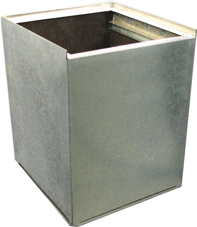
www.hi-velocity.com

                  Table of Contents

                 Setting up your LV-B System - Pg. 4
                        Unit Selection, Quality Assurance

                    Air Handler Placement - Pgs. 5
                   Placement, Unit Configuration, Clearances

                Water Cooling Module (WCM) - Pg 6

                Hot Water Coil (HWC) Add-on - Pg 6

                  Electric Strip Heater (ESH) - Pg. 7

                             Return Air - Pg. 7
             Return Cutout Dimensions, Return Air Base, Filter Rack

              Hi-Velocity Air Purification System Pg. 8
              Hi-Velocity Air Purification System, HE PS Dimensions

                            User Guide - Pg 8
                   IAQ, Filter Maintenance, System Efficiency

                     Installation Check List - Pg. 8

            HEB Circuit Board & WEG Drive - Pgs. 9-18
         HEB Board, WEG Drive, HEB Wiring Diagram, Extended WIring
                     Diagrams, Fan Speed Adjustment

                    Trouble Shooting - Pgs. 19-25
Motor Running Too Fast, Motor Running Too Slow/Not Running, 24V Clg, 24V Htg.,
                         Outdoor Unit, Short Cycling

                     Appendix Pages - Pgs. 26-27
 LV-B Air Handler Specifications (Standard & Metric, Quick Product Sizing Guide)

                    Warranty Information - Pg. 28

                                       -2-                                         © 1995-2021 Energy Saving Products Ltd.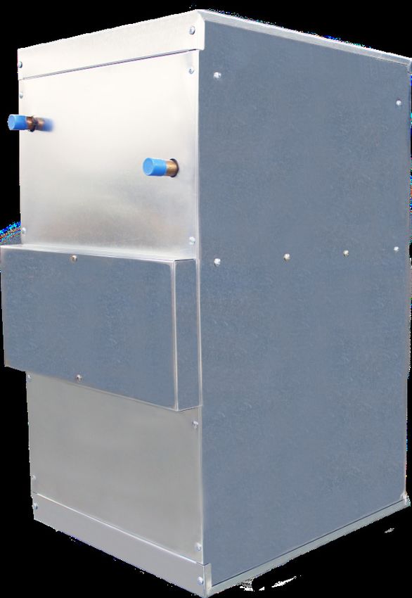
Module LVB
                                                              LV-B Series Air Handler Installation (3/28)
                                  www.hi-velocity.com

             The LV-B System
                    By Energy Saving Products Ltd.

   All Product                                                     LV-B Air Handler
Sizing on Pg. 26                                                   Specs Pg. 25

      Heating Options                                   Cooling Options

          Hot Water Coil                                     Refrigerant Module

            Electric Strip Coil                              Water Coil Module

                             Other Options

           Return Air                                       Hi-Velocity Air
                                                            Purification System

                                          -3-                                    © 1995-2021 Energy Saving Products Ltd.
Module LVB
                                                                                                     LV-B Series Air Handler Installation (3/28)
                                                           www.hi-velocity.com

    When sizing an LV-B air handler for a residential system, it               Sweat water connections are 3/4” for the LV-B-751/1051 and
is necessary to have an accurate heat loss/gain done for the                1” for the LV-B-1751. All lines should be piped so as not to restrict
structure. This will ensure the proper equipment is used for                use of the access panels, filter section, or electrical enclosure.
cooling and heating. A heat loss/gain is done for each room,
with all rooms added together to find the total BTUH load for                Refer to the back of this manual for all specifications,
the building. With the total load known, the appropriate air                measurements, etc.
handler can be chosen from Pg. 25.
                                                                              Air handlers are to be located indoors, however, attic, crawl
                                                                            space and garage conditions are fully acceptable. The air handler
                                                                            unit can be positioned in a Horizontal, Hi-Boy, or Counterflow
  IMPORTANT: The LV-B Air Handler is                                        position and can be suspended from the ceiling or placed directly
  not to be used for temporary heating                                      on the floor.

  or cooling during the construction of
                                                                              When potential for gravity flow of the hot water exists, spring
  the structure. If used in this capacity                                   check valves may be needed on both the supply and return lines.
  all warranties will be null and void.

   Air handler units specified in this section shall be designed as
a closed loop hydronic air handler system, with published BTUH
ratings and entering water temperatures between 110°F and                     Please read the ENTIRE manual before
190°F. The system shall allow for heating, DX or chilled water                beginning installation as this will help avoid
cooling, and heat pump applications with electric coil back-
ups. Entering water temperature and BTUH outputs shall match
                                                                              mistakes that may cost time and money.
performances listed on Pg. 25.

                    Quality Assurance
  Air handler units shall be a total indoor air quality system
complete with heating, cooling and air filtration, with the
possibility of humidity control and fresh air make up. The air                                       Air Handlers
handler must be factory manufactured, assembled and tested.                    The LV-B air handler is manufactured with a direct drive,
                                                                            permanently lubricated motor that is mounted within the blower.
  All equipment furnished under this specification shall
                                                                            All LV-B air handlers are single side access. The blower assembly
comply with the standards set out by the following standards
                                                                            can be easily slid out by removing the electrical box and then
organizations:
                                                                            removing the three mounting bolts that attach the blower to the
  CSA 		           Canadian Standards Association                           center plate.
  CE		             European Conformity

  UL 		            Underwriters Laboratories
                                                                                                       Disclaimer
  The air handler units shall be designed, rated, and approved
by CSA/UL.                                                                     Energy Saving Products Ltd. reserves the right to discontinue,
                                                                            make changes to, and add improvements upon its products at
                                                                            any time without public notice or obligatiion. The descriptions
   The air handler units shall have pre-wired controls consisting
                                                                            and specifications contained in this manual were in effect at
of a 24V transformer, printed circuit board and variable
                                                                            printing. Some illustrations may not be applicable to your unit.
frequency drive. The circuit board shall be capable of providing
heating, cooling and constant fan. Motors shall be 3 phase with
published amp draws.

                                                                      -4-                                               © 1995-2021 Energy Saving Products Ltd.
Module LVB
                                                                                                               LV-B Series Air Handler Installation (5/28)
                                                                         www.hi-velocity.com

                                 Placement
                                                                                                    Hanging the Air Handler Unit
   When installing the air handler, keep these points in mind:

   -         Serviceability and access to the unit.                                       Quite often, the best location for the air handler unit is
                                                                                       suspended from the ceiling of the mechanical room, in the
   -         Maximizing usable floor space.
                                                                                       horizontal position (Fig. 03). This will allow for more floor space
   -         Location of heating/cooling source to the air handler.                    in the room, and will minimize the duct work needed to connect
                                                                                       to the air handler unit.

   As previously stated, the air handler can be positioned in many
different orientations. When placed in the Hi-Boy position, supply                        The Hi-Velocity air handler can be suspended in any position,
air is fed from the top of the unit (Fig. 01). When placed in the                      using most industry standard hanging support systems.          Redi-
Counterflow position, supply air is fed downwards from the unit                        Rod, All Thread, C-Channel or Unistrut are some of the building code
(Fig. 02).                                                                             acceptable hanging systems. Use these in conjunction with spring
                                                                                       or rubber isolators to ensure a sturdy hanging support system.
                                                                                       These isolators will absorb most of the vibrations generated by the
       Fig. 01 - Hi-Boy
                                                                                       air handler system, eliminating any sound transfer.

                                                 Fig. 02 - Counterflow

                                                                                       Securing the Air Handler to the Hanging System

                                                                                          In most cases, fastening the hanging system near the corners
                                                                                       of the outside cabinet of the air handler will be acceptable.
                                                                                       However, in some cases, brackets may be needed to secure the
                                                                                       air handler to the hanging system.

                                                                                                                 Clearances
                                                                                         Clearance is only needed on the access side of the units.
                                                                                       However, ensure that there is a small space between the unit
                                                                                       and any other surface to prevent vibration transfer. In order to
                                                                                       maintain and service the air handler unit, the minimum clearances
                                                                                       required on the access side are (Table 01).

                                                                                              Table 01 – Air Handler Clearances
                                                                                        Unit                         Inches (mm)
                                                                                         LV-B-751                     18” (457mm)
                          Fig. 03 - Horizontal installation
                                                                                         LV-B-1051*                   22” (559mm)
                                                                                         LV-B-1751                    32” (813mm)
                                                                                           *Add an additional 4” for Electric Strip Coils

                                                                                                    Refrigerant Cooling Module
                                                                                         Due to the high volume of air produced by LV-B air handlers,
                                                                                       the use of a third party blow-through coil such as an A-Frame or
                                                                                       N-Frame coil is suitable. When using an RBM, RPM-E or RCM
                                                                                       cooling module, consult with the parts list or the factory for
                                                                                       proper match-up recommendations.

                                                                                 -5-                                              © 1995-2021 Energy Saving Products Ltd.
Module LVB
                                                                                                             LV-B Series Air Handler Installation (6/28)
                                                                www.hi-velocity.com

           Water Coil Module (WCM/WM)
                                                                                      Fig. 07 - Hot Water Coil easily slides into the Air Handler

   The water coil comes as a module and must be installed in
the vertical position on the return air side of the air handler.
The WCM/WM come supplied with two L mounting brackets
for connection to the air handler (Fig. 06). For WCM/WM
dimensional information and sweat water connection sizes
refer to the manual shipped with the coil, also available on our
website.
                   Piping the WCM/WM
   When the potential for gravity flow of the hot water exists,
check valves may be needed on both the supply and return lines.
Figs. 08 and 09 give an example of this. All lines should be piped
so as not to restrict access to the front panels, filter section, or
electrical enclosure. Size your supply and return lines according
to Table 02.
           Table 02 – WCM/WM pipe sizing
    Zone BTUH               Pipe Size                Pipe Size
     Heat loss            up to 40 feet            40 – 100 feet
 0 - 35,000                      5
                                  ⁄8”                   3
                                                         ⁄4”
 35,001 - 70,000                 3
                                  ⁄4”                   1”
                                                                                                  Fig. 08 - Hot water tank: Side take-offs
 70,001 - 140,000                1”                    1 1⁄4”
                                                                                                   H                                 SUPPLY
                     Fig. 06 - Mounting Brackets
                                                                               Domestic       C                                     RETURN
                                                                               hot water
                                                                               mixing valve
                                                                               (optional)

                                                                                                                                          Air Handler
                                                                                 Domestic
                                                                                 cold water
                                                                                                        C     H

                                                                                                         Dual       SUPPLY
                                                                                                       Purpose
                                                                                                       hot water
                                                                                                         tank      RETURN

                  Hot Water Coil Add-on
                                                                                          Fig. 09 - Hot water tank: Without side take-offs

  The Hot Water Coil Add-on is easily installed in the LV-B air                                    H                               SUPPLY

handler. With heating, condensate is not a consideration and the               Domestic                                            RETURN
                                                                                              C
coil can be mounted on the supply side of the blower (Fig. 07).                hot water
                                                                               mixing valve
                                                                               (optional)
   With the removal of the front panels, the coil can be slid in place
on the supply side of the blower. For Hot Water Coil dimensional                                                                       Air Handler
information refer to our website.                                                Domestic
                                                                                 cold water
                                                                                                         C    H

                Piping the Hot Water Coil
                                                                                                         Dual
                                                                                                       Purpose
                                                                                                       hot water
   Figs. 08 and 09 illustrate typical pipe runs from a dual purpose                                      tank

hot water tank to a air handler. These drawings are only for
reference as all piping has to be run according to local code.

                                                                         -6-                                                    © 1995-2021 Energy Saving Products Ltd.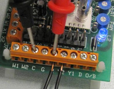
Module LVB
                                                                                                          LV-B Series Air Handler Installation (7/28)
                                                                  www.hi-velocity.com

              Electrical Strip Heater (ESH)
  The Electrical Strip Heater slides into the air handler, on the                  Once the placement of the return has been decided, the return
supply side of the blower (Fig. 07). Once the front access doors                air knockout(s) can be cut. (Fig. 10) The premeasured guide
have been removed, the ESH can be slid into place.                              cuts supplied with the air handler should always be used to
                                                                                make the initial cut. After the first cut using the return air
   The ESH is labeled with a directional airflow sticker; when
                                                                                knockout(s) a metal shear must be used to maximize the
placing the ESH the sticker shall be in the direction of the air
                                                                                return air cutout opening size. This allows it to match more
flow.
                                                                                closely to the filter, cooling coil or return air ducting size to
                                                                                maximize flow capacity.
            Wiring the Electrical Strip Heater
   Before wiring in the ESH, make sure all power sources are                                    Return Air Base (Optional)
disconnected. The wiring diagram is on the inside of the ESH
front panel, or refer to Pg. 10. Use only wires suitable for 167ºF               Energy Saving Products manufactures a return air base that
(75ºC); wires shall be sized according to local electrical code.                matches up to the air handler units.

   Use only class 2 wiring for the Control Circuit connections                     The return air base provides a stand for the air handler when
between the heater terminal 1, terminal 2 and the zone valve                    placed in vertical orientation, and provides an easy mounting
terminals. Please note, the ESH must be wired to a dedicated                    location for modular coils and filter racks. It can also be used as
breaker, separate from the air handler.                                         a transition and mixing box for the return air. All return air bases
                                                                                come acoustically lined with half-inch sound absorbing insulation.
  For Electrical Strip Heater Specifications, please refer to the
manual shipped with the coil, also available on our website:
www.hi-velocity.com
                          Return Air                                                                                                               E

  The return air duct is not supplied with the LV-B Air Handler
System. It is to be supplied and installed by the contractor.
The return air and fresh air make-up ducts are to be installed                              A
according to local building code.                                                                                                              D

                    Return Air Cutout
  All LV-B air handlers are shipped with the return air knockouts
pre-measured for multiple configurations. Table 03 contains the
pre-measured dimensions for the return air knockouts.
                                                                                                    C
                                                                                                                            B
    Table 03 – Return Air Cutout Dimensions
Model                                     Dimensions
                                                                                                        Hi-Velocity Return Air Base
LV-B-751                           9 ” X 131/2” (241mm x 343mm)
                                    1/2

LV-B-1051                         141/2” X 131/2” (356mm x 343mm)
LV-B-1751                          21” X 177/8” (533mm x 454mm)
                                                                                                Return Air Base Dimensions
                                                                                                     A           B          C             D             E
                     Fig. 10 - Return air cutout

                                                                                    RA-50/750      221⁄2”      181⁄2”    141⁄2”         211⁄2”         1”
                                                                                                   (572mm)     (470mm)   (368mm)        (552mm)      (25mm)

                                                                                   RA-70/1050      221⁄2”      181⁄2”    191⁄2”         211⁄2”         1”
                                                                                                   (572mm)     (470mm)   (495mm)        (552mm)      (25mm)

                                                                                     RA-1750       221⁄2”      241⁄2”    261⁄2”         211⁄2”         1”
                                                                                                   (572mm)     (622mm)   (673mm)        (552mm)      (25mm)

                                                                          -7-                                                   © 1995-2021 Energy Saving Products Ltd.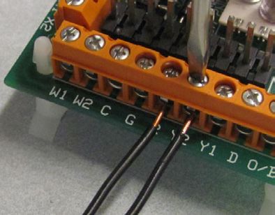
Module LVB
                                                                                                                      LV-B Series Air Handler Installation (8/28)
                                                                         www.hi-velocity.com

                      Options & Add-Ons
            Hi-Velocity Air Purification System
                                                                                                                   LV-B User Guide

                                                                                                               Indoor Air Quality (IAQ)
                                                                                                  Ensure that there is always a filter in place and check every
                                                                                              month to ensure that the filter is clean. The amount of time
                                                                                              between filter changes and cleaning will be dependant upon the
                                                                                              living habits of the homeowner. We recommend replacing filters
    Easily installed on any Hi-Velocity or existing HVAC System,
                                                                                              every 6 months. With a clean air filter, you not only have cleaner
 the optional HE PS gives consumers unsurpassed indoor air
                                                                                              air to breathe, but you will also help maintain unit efficiency, as
 quality. The HE PS will work at the airflow rates of the LV-B-1051
                                                                                              well as increase the operating life of the unit.
 only. For 3 stage filtration on the LV-B-1751, we recommend
 using the HE PS-1750.
    Three powerful technologies in one Air Purification System:
                                                                                                          System Efficiency/Performance
    •      Electrostatic MERV-13 Filter Removes Allergens
                                                                                                 A big misconception that people have is that by turning off
    •      Photo-Catalytic Oxidation destroys toxic chemicals
           and eliminates household odors                                                     the air conditioning when they leave home, they save on cooling
    •      Ultraviolet Light Kills Disease Germs on Contact                                   costs. This is not necessarily true as the system will need to run
                                                                                              longer and harder when pulling the house down to temperature
                                 Filter Rack                                                  after being shut off for a large amount of time. Keeping the
   Also available from Energy Saving Products is a FR Filter Rack                             temperature within a small range when there are no loads from
(1”) and a FR-4 Filter Rack (4”). The FR 1” filter is a MERV 3 which is                       human use will result in less overall energy consumption.
14% efficient and the FR-4 is a 4” MERV 13 which is 85% efficient.
Aftermarket filters may be used with the Hi-Velocity filter racks.
(See filter dimensions below)
                                                                                                                  Installation Checklist
                                                                                                 Ensure that all electrical connections are tight, and that any
                                                                                              packing or shipping restraints are removed from both the air
                                                                                              handler, and the outdoor unit. With the power to the condensing
                                                                                              unit off, check the thermostat for normal operation and proper
                                                                                              airflow from all vents. Do not run the air handler without a filter
     1” Filter Rack and Filter               4” Filter Rack and Filter                        in place.

                           Filter Dimensions                                                      Observe the system pressures during the initial start-up and
  Unit           750/751                 1050/1051                 1750/1751                   charging of the system. Refer to the outdoor or indoor coil
                                                                                               manufacturer’s charging guidelines. Check the voltage and amp
   FR         14” X 1” X 18”            18” X 1” X 18”           24” X 1” X 26”                draw of both the air handler, and the outdoor unit. The voltages
  Filter   (355mm x 25mm x 457mm)    (457mm x 25mm x 457mm)    (609mm x 25mm x 457mm)
                                                                                               must be within 10% of the rating plate data. If more than 10%
              14” X 4” X 18”            19” X 4” X 18”                                         is noted, contact your local electrical company. Check that the
  FR-4
                                                                        N/A
  Filter   (355mm x 101mm x 457mm)   (483mm x 101mm x 457mm)
                                                                                               amp draws of both units are within the information printed on
                                                                                               the unit rating plates.

        Hi-Velocity Portable Air Purification System

                                                                                                  In the event of difficulty during the start-
                                                                                                  up procedure, please refer to the trouble
                                                                                                  shooting flow charts (Pgs. 17-24) to
                                                                                                  assist you in determining the problem.
    For room to room air purification, Energy Saving Products
 also offers the P-20 Portable Hi-Velocity Air Purification System,
 a powerfully advanced stand-alone system that has 5 steps to
 give you the cleanest air possible:
                                                                                        -8-                                              © 1995-2021 Energy Saving Products Ltd.
Module LVB
LV-B Series Air Handler Installation (9/28)
www.hi-velocity.com
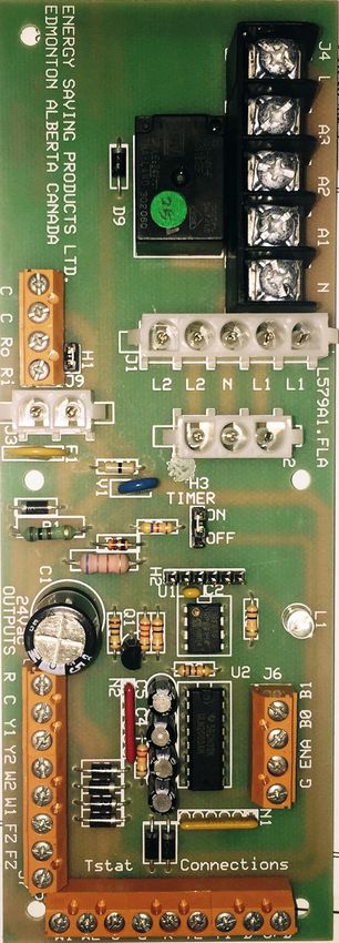
Hi-Velocity Systems HEB Circuit Board
The Hi-Velocity LV-B Series Air Handler utilizes our HEB Circuit Board. This circuit board manages thermostat calls and makes wiring
in components (i.e. Boilers & Condensers) simple and easy.
Auxiliary Relay Pump Timer
Terminals (Heating) Indicator Light
T’Stat
Connections
Emergency 24v Pump Timer Condenser/Zone
Disconnect Auto-Reset on/off Switch Valve Connections
Fuse
Features:
• If you wish to have the timer cycle operate at a
• Wiring the circuit board is a quick and simple task.
specific time of day, simply turn off power to the air
• Clearly labeled connections. handler unit for ten seconds at that time, and then turn
• No additional relays typically required. the power back on.
• Circuit Board manages thermostat calls and puts out • If you do not need to use the timer, move the jumper
appropriate control signals to the WEG VFD to initiate fan speed. header from the On pins to the Off pins and it will be
• Circuit board is capable of controlling boilers, dual purpose hot disabled.
water heaters, heat pumps, and geothermal systems, as well as • Circuit board is equipped with an emergency
disconnect feature. If there’s an emergency this feature
our manufactured slide-in electric strip heaters (ESH).
will de-energize all fan speeds and 24 volt signals.
• The circuit board is also designed to send control signals to
• For this emergency disconnect feature to be active, a
cooling sources such as condensing units, chillers, heat pumps jumper header must be removed from the pins located
and geothermal systems. close to the emergency disconnect terminal strip. (H1)
• Circuit board features an auxiliary relay with dry contact
connections, so that any applications requiring 24v, 120v, Function:
230v or dry contacts (boilers, hot water heaters, heat pumps
• Manages input power and through the use of a
& humidifiers) can be automatically started when there is a call transformer it supplies 24vac to additional equipment.
for heat. • Organizes all thermostat inputs and prioritizes them
• Circulator timer chip is provided to prevent water stagnation in accordingly.
potable water systems and to provide pump rotor protection for • Sends a control output signal to the VFD, dependent
water source heating and cooling. on thermostat call.
G=Ground F=Fan H=Heat C=Cool H&C=DH
-9- © 1995-2021 Energy Saving Products Ltd.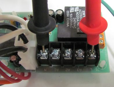
Module LVB
                                                                                                      LV-B Series Air Handler Installation (10/28)
                                                             www.hi-velocity.com

                                           CFW300 WEG Variable Frequency Drive
                  PLEASE NOTE: CFW10 has slightly different appearance, terminals and wiring are the same.

                                                        The Hi-Velocity HE-Z Series Air Handler utilizes a WEG Variable
                                                        Frequency Drive to run its 3-phase motor. The WEG VFD is a
                                                        reliable and robust motor control that will provide many years
                                                        of issue free operation.
    Features:
    • Purposely oversized to ensure increased reliability and higher efficiencies at peak load
    • Features inherent with VFD allows for minimum power consumption at reduced loads (
© 1995-2021 Energy Saving Products Ltd.
LV-B Series Air Handler Installation (11/28)
CFW300 HE-B / LV-B / VFD POWER INPUT: 110-127/1/50-60
NOTE: CFW10 HAS SLIGHTLY DIFFERENT APPEARANCE - TERMINALS AND WIRING ARE THE SAME
Module LVB
LV-B Air Handler - HEB Circuit Board/CFW300 WEG Wiring Diagram
THERMOSTAT CONNECTIONS FAN SPEED ADJUSTMENT (COOLING, HEATING OR RECIRCULATION FAN) NOTES:
- POWER FAN COIL UNIT. 1) USE THERMOSTAT FAN SWITCH TO DISABLE/ENABLE CONTINUOUS
PLEASE NOTE: CFW10 has slightly different appearance, terminals and wiring are the same.
R - 24 VAC OUTPUT
W1 - FIRST STAGE HEAT - ENSURE ALL OUTLETS ARE OPEN. FAN.
W2 - SECOND STAGE HEAT - ENERGIZE THE THERMOSTAT SETTING TO BE ADJUSTED. (COOLING, HEATING 2) ‘C’ TERMINAL ON THERMOSTAT (COMMON) IS NOT NEEDED FOR SOME
(OR SINGLE STAGE) OR RECIRCULATION FAN). THERMOSTATS CONSULT THERMOSTAT INSTRUCTIONS FOR DETAILS.
Y1 - FIRST STAGE COOLING - ON THE WEG - “CFW300” PRESS THE PARAMETER BUTTON (P) UNTIL THE 3) W1 AND W2 ACTIVATES AUXILIARY RELAY (A3) ON CALL AND CAN BE
Y2 - SECOND STAGE COOLING PARAMETER LIGHT (RED) IS ILLUMINATED. USED WITH A1 AND/OR A2 AS DRY CONTACTS, ARMED 24VAC FROM
(OR SINGLE STAGE) - USING THE ARROW BUTTONS SCROLL DOWN TO PARAMETER “000”. THE ‘R’ TERMINAL, OR ARMED 110v FROM THE ‘L’ TERMINAL.
C - 24 VAC COMMON - PRESS THE PARAMETER BUTTON (P) AGAIN TO ENTER THE PARAMETER “000”. 4) AUXILIARY HEATING RELAY TIMER ACTIVATES CIRCUIT FOR 5 MINUTES
G - THERMOSTAT FAN SWITCH - CHANGE P 000 TO A VALUE OF “005”. THIS UNLOCKS THE DRIVE AND ALLOWS EVERY 24 HOURS STARTING WHEN POWER IS APPLIED TO THE UNIT.
D - DEHUMIDIFICATION SPEED YOU TO CHANGE OTHER PARAMETERS. 5) SEE INSTALLATION MANUAL FOR MORE DETAILED WIRING DIAGRAMS.
O/B - HEATPUMP REVERSING - ONCE PARAMETER “000” IS SET TO A VALUE OF “005” THE DRIVE IS UNLOCKED 6) FOR SINGLE STAGE COOLING OPERATION USE Y2, OTHERWISE THE
THE FAN SPEEDS CAN BE ADJUSTED VIA PARAMETERS 128, 129, 130 AND 131. FREEZE STAT WILL BE BYPASSED.
EMERGENCY DISCONNECT 7) FAILURE TO SET PROPER AIR FLOW AND/OR OPERATION OF THE
C - 24 VAC COMMON ► 00.0 HZ IS THE MINIMUM SPEED - 66.0HZ IS THE MAXIMUM SPEED. SYSTEM MAY RESULT IN DAMAGE TO EQUIPMENT.
C - 24 VAC COMMON
8) FAILURE TO READ AND FOLLOW ALL INSTRUCTIONS CAREFULLY
Ro - 24 VAC OUTPUT Useful Parameters BEFORE INSTALLATION COULD CAUSE PERSONAL INJURY AND/OR
Ri - 24 VAC INPUT
P 000 To unlock drive change value to “005" CAUTION PROPERTY DAMAGE.
9) ENSURE THAT THE FILTER IS KEPT CLEAN AT ALL TIMES.
www.hi-velocity.com
FOR SINGLE STAGE
AUXILIARY HEATING RELAY P 002 To display Hz output COOLING OPERATION 10) MOTOR HAS PERMANENT LUBE BEARINGS AND DOES NOT REQUIRE
N - NEUTRAL USE Y2 OTHERWISE THE
P 030
Drive Heatsink Temperature OILING.
L - LINE VOLTAGE (CFW10= P 008) FREEZESTAT WILL BE
BYPASSED 11) WARRANTY VOID IF FAN COIL UNIT IS USED DURING CONSTRUCTION.
A1 - AUXILIARY NORMALLY OPEN
P 128 To adjust Constant Fan Speed
A2 - AUXILIARY NORMALLY CLOSED
-11-
A3 - AUXILIARY COMMON P 129 To adjust Cooling Fan Speed
Ground
G BK WH
FIELD WIRED
LINE IN
24 VAC OUTPUT CONNECTIONS P 130 To adjust Heating Fan Speed L1
Equipment
FZ - FREEZE STAT (FOR Y2) P 131 To adjust Dehumidification Fan Speed Ground N
FZ - FREEZE STAT (FOR Y2)
W1 - HEATING (W1) 24 VAC OUTPUT 24v OUTPUT EMERGENCY DISCONNECT 110-127/1/50-60
(3 PHASE)
W2 - HEATING (W2) 24 VAC OUTPUT J3
WEG CONTROLLER J5 J7
Y2 - CONDENSING UNIT 24 VAC OUTPUT
318.28 Pcbw-002sep-043
CFW 300
W1 W2 C G R Y2 Y1 D O/B
Y1 - CONDENSING UNIT 24 VAC OUTPUT FZ FZ W1 W2 Y2 Y1 C R Ri Ro C C
N
110-127v
1 2 3 4 5 6 7 8 9 10 11 12
C - 24 VAC COMMON
G WH R BK F1 J9
HEB CIRCUIT BOARD
H1 J1
R - 24 VAC OUTPUT
THERMOSTAT
O
L2 L2
I
AUXILIARY RELAY
JUMPER PIN SETTINGS (HEATING)
TIMER
H3
W
N
H1 EMERGENCY DISCONNECT: REMOVE
ON
OFF
PE L/L1 N/L2
PIN IF WIRED TO EMERGENCY DISCONNECT.
L1 L1
V
H3 TIMER: AUXILIARY RELAY TIMER (SEE NOTES).
U
P
G F H C J2 N A1 A2 A3 L
PE
LED LIGHT INDICATORS
Orange
White
J4
Black
LED - GREEN LIGHT, PUMP TIMER
Red
PUMP TIMER STATUS 110-127v POWER CABLE 110-127 VAC
1 2 3 4
ON: (ACTIVE) 24v / 20va
TRANSFORMER
ON: (INACTIVE)
OFF: REFER TO COMPLETE COMMISSIONING REPORT PRIOR TO NORMAL OPERATION. REPORT IS
2 SECONDS AVAILABLE WITH THE INSTALLATION MANUAL OR ONLINE AT WWW.HI-VELOCITY.COM.
HE-B/LV-B 110V
102020Module LVB
LV-B Series Air Handler Installation (12/28)
www.hi-velocity.com
LV-B Air Handler - HEB Circuit Board Wiring
24 VAC Input terminals (tstat connections):
W1: 1st stage Heating, Runs at the heating speed when 24v (R) is supplied.
2nd stage Heating, Runs at the heating speed when 24v (R) is supplied. The difference
between a W1 call and a W2 call is the output terminal that will be energized with 24v.
W2:
(W1 energized on t-stat terminal strip will provide 24v to W1 on output terminal strip, W2
energized on t-stat terminal strip will provide 24v to W2 on output terminal strip,)
C: Common
G: Constant Fan, Runs at the Constant Fan speed when 24v (R) is supplied.
24 volt supply
R: (Note: As long as Transformer is connected & the Fire Disconnect/Jumper Pin Header is
Present)
Y2: 2nd stage Cooling, Runs at the Cooling speed when 24v (R) is supplied.
1st stage Cooling, Runs at the Cooling speed when 24v (R) is supplied. The difference be-
tween a Y1 call and a Y2 call is the output terminal that will be energized with 24v. (Y1 en-
Y1:
ergized on t-stat terminal strip will provide 24v to Y1 on output terminal strip, Y2 energized
on t-stat terminal strip will provide 24v to Y2 on output terminal strip,)
D: Runs at Dehumidification speed when 24v (R) is supplied.
O/B: Heat Pump Reversing
Fan Speed Priority Sequence (from highest to lowest): D = 1st Y = 2nd W = 3rd G=4th
24 VAC Output terminals (24v output connections):
24 volt Supply
R: (Note: As long as Transformer is connected & the Fire Disconnect/Jumper Pin Header is
Present)
C: Common
Y1: 1st Stage Cooling Equipment
Y2: 2nd Stage Cooling Equipment*
W2: 24v Output to 2nd Stage Heating Equipment.
W1: 24v Output to 1st Stage Heating Equipment.
FZ: Freeze Stat Connection*
FZ: Freeze Stat Connection*
*Note: FZ to FZ recommended to be wired to Freeze Stat (Anti-Ice Control). For chilled water applications, a jumper between FZ to
FZ must be installed to complete the Y2 - 24V Signal to Y on Condenser.
-12- © 1995-2021 Energy Saving Products Ltd.Module LVB
LV-B Series Air Handler Installation (13/28)
www.hi-velocity.com
LV-B Air Handler - HEB Circuit Board Wiring Cont’d
Emergency Disconnect:
C: Common
C: Common
Provides 24VAC to the entire HEB board. In order for “Ro” to receive power it must be con-
nected to terminal “Ri”. This can be done via the two pin jumper header (H1) located above
Ro: the terminal strip, a wire jumper or normally closed safety device installed between “Ro” and
“Ri”. The jumper pin header (H1) will need to be removed to activate the emergency
disconnect option.
Receives 24VAC direct from the transformer. Power must then be sent to the “Ro” terminal
Ri:
to be distributed throughout the rest of the HEB board.
3 Pin Jumper Terminals:
H1: Emergency Disconnect
Pump timer cycles the pump on for 5 minutes every 24 hours to prevent stagnant water.
H3 Timer: (on/off) The jumper pin header (H3) will need to be in the ON position for the timer to be
active.
Auxiliary Heating Relay:
N: Neutral
L: Line Voltage
A1: Auxiliary Relay Normally Open
A2: Auxiliary Relay Normally Closed
A3: Auxiliary Relay Common
Control Signal:
J6: 4 Terminal Control Signal sending appropriate call to WEG VFD
-13- © 1995-2021 Energy Saving Products Ltd.SAMPLE AUXILIARY RELAY WIRING OPTIONS FOR HEATING (W1 OR W2)
L L L
1 Stage Cooling 1 Stage Heating 1 Stage Cooling 2 Stage Heating
A3 R A3 A3
Heatpump A2 A2 A2
HEATING MODE: REFER TO
AUXILIARY CONTACT INFORMATION A1 A1 A1
FOR W1 AND W2
J4
N N N
J4
C
L
L
DRY CONTACTS 24 VAC 115 VAC
R
RELAY WIRING RELAY WIRING RELAY WIRING
R
A3
A3
A2
A2
SAMPLE AUXILIARY RELAY WIRING OPTIONS FOR HEATING (1 STAGE - W2 ONLY)
DRY CONTACT T R
A1
A1
L
TO BOILER T C
N
N
Y1 A3
C Y C Y Y O/B R W1 Y2 115v
C Y1 Y2 W2 W1 FZ FZ
A2
C Y1 Y2 W2 W1 FZ FZ
EXTERNAL W2 CIRCULATOR
CONDENSER CONDENSER
J7
SPDT RELAY
J7
24 VAC COIL W1 A1
ANTI-ICE W1 W2 C G R Y2 Y1 D O/B ANTI-ICE W1 W2 C G R Y2 Y1 D O/B
CONTROL CONTROL
FZ
N
J5
J5
DRY CONTACTS AND 115 VAC FZ
RELAY WIRING
W C G R Y SAMPLE AUXILIARY RELAY WIRING OPTIONS FOR HEATING
(W1 OR W2)
W C G R Y DRY CONTACT EXTERNAL
E W2 C G R Y O/B SPDT RELAY
THERMOSTAT TO BOILER
E W2 C G R Y O/B 24 VAC COIL
T T
THERMOSTAT 115 V TO
CIRCULATOR
R
-14-
2 Stage Cooling 1 Stage Heating 2 Stage Cooling 3 Stage Heating
Heatpump C L
HEATING MODE: REFER TO Y1
A3
AUXILIARY CONTACT INFORMATION Y2
FOR W1 AND W2
A2
J4
W2
J4
ANTI-ICE
ANTI-ICE (W2) 24v OUTPUT
CONTROL
www.hi-velocity.com
CONTROL W1 A1
L
L
(W1) 24v OUTPUT
FZ
R
N
R
FZ
A3
A3
O/B
A2
W1 W2 C G R Y2 Y1 D
A2 W2 - SINGLE STAGE OR 2ND STAGE HEAT
A1
24v, DRY CONTACTS AND 115 VAC
require, please call the technical department at Energy Saving Products Ltd. for further assistance.
A1
W1 - FIRST STAGE HEAT RELAY WIRING
N
N
C Y1 Y2 O/B R W1 C Y1 Y2 O/B R W1
FOR SINGLE STAGE OPERATION
C Y1 Y2 W2 W1 FZ FZ
C Y1 Y2 W2 W1 FZ FZ
CONDENSER
J7
CONDENSER USE W2 & Y2 TERMINALS
J7
W1 W2 C G R Y2 Y1 D O/B W1 W2 C G R Y2 Y1 D O/B
LV-B Air Handler - Extended Wiring Diagrams
R - 24 VAC OUTPUT N - NEUTRAL
J5
J5
W1 - FIRST STAGE HEAT L - LINE VOLTAGE
W2 - SECOND STAGE HEAT A1 - AUXILIARY NORMALLY OPEN
(OR SINGLE STAGE) A2 - AUXILIARY NORMALLY CLOSED
Y1 - FIRST STAGE COOLING A3 - AUXILIARY COMMON
Y2 - SECOND STAGE COOLING
E W2 C G R Y2 Y1 E W2 C G R Y2 Y1 O/B (OR SINGLE STAGE) FZ - FREEZE STAT
THERMOSTAT E W2 C G R Y2 Y1 O/B C - 24 VAC COMMON FZ - FREEZE STAT
THERMOSTAT G - THERMOSTAT FAN SWITCH W1 - HEATING (W1) 24V OUTPUT
Module LVB
D - PRIORITY (RUNS AT W SPEED) W2 - HEATING (W2) 24V OUTPUT
O/B - HEATPUMP REVERSING VALVE Y2 - CONDENSING UNIT (Y2) 24V OUTPUT
Y1 - CONDENSING UNIT (Y1) 24V OUTPUT
C - 24 VAC COMMON
R - 24 VAC OUTPUT
HE-B-Extended-Wiring-Pg-1-082615
LV-B Series Air Handler Installation (14/28)
Extended wiring diagrams for the various applications the Hi-Velocity LV-B model can be used for. If you do not find the wiring configuration you
© 1995-2021 Energy Saving Products Ltd.© 1995-2021 Energy Saving Products Ltd.
Extended wiring diagrams for the various applications the Hi-Velocity LV-B model can be used for. If you do not find the wiring configuration you
CHILLED WATER WIRING
LV-B Series Air Handler Installation (15/28)
1 Stage Cooling 2 Stage Cooling
c/w chilled water circulator c/w chilled water circulator
Module LVB
COOLING
COOLING CIRCULATOR
CIRCULATOR HEATING MODE OPTIONS: REFER TO
AUXILIARY CONTACT INFORMATION
HEATING MODE OPTIONS: REFER TO
FOR W1 AND W2
AUXILIARY CONTACT INFORMATION
FOR W1 AND W2
J4
J4
LV-B Air Handler - Extended Wiring Diagrams
L
L
A3
A3
A2
A2
A1
A1
require, please call the technical department at Energy Saving Products Ltd. for further assistance.
N
N
R
R
C Y1 Y2 W2 W1 FZ FZ
C Y1 Y2 W2 W1 FZ FZ
CHILLER
www.hi-velocity.com
C Y
CHILLER CONTACTS
C Y
CONTACTS
J7
W1 W2 C G R Y2 Y1 D O/B
J7
W1 W2 C G R Y2 Y1 D O/B
J5
J5
-15-
C G R Y
C G R Y
C G R Y2 Y1
C G R Y THERMOSTAT
THERMOSTAT
1 Stage Cooling (Only)
c/w chilled water circulator
HEATING MODE OPTIONS: REFER TO
AUXILIARY CONTACT INFORMATION
FOR W1 AND W2
J4
L
R C Y1 Y2 W2 W1 FZ FZ
A3
Chilled water
A2
Circulator
A1
N
C Y CHILLER
CONTACTS
J7
W1 W2 C G R Y2 Y1 D O/B
J5
C G R Y
C G R Y
THERMOSTAT HE-B-Extended-Wiring-Pg-2-082615HEAT PUMP C/W CONDENSER DEFROST CYCLE - BOILER BACK-UP
1 Stage Cooling 2 Stage Heating 2 Stage Cooling 3 Stage Heating
Heat pump c/w condenser defrost cycle Heat pump c/w condenser defrost cycle
DRY CONTACT EXTERNAL DRY CONTACT
TO BOILER SPDT RELAY TO BOILER EXTERNAL
24 VAC COIL T T SPDT RELAY
T T
24 VAC COIL
HEATING MODE: REFER TO HEATING MODE: REFER TO
AUXILIARY CONTACT INFORMATION AUXILIARY CONTACT INFORMATION
FOR W1 AND W2 FOR W1 AND W2
J4
J4
L
L
A3
A3
A2
A2
A1
A1
N
N
-16-
ANTI-ICE
CONTROL
R
R
www.hi-velocity.com
require, please call the technical department at Energy Saving Products Ltd. for further assistance.
C Y O/B R W1 C Y1 Y2 O/B R W1
C Y1 Y2 W2 W1 FZ FZ
C Y1 Y2 W2 W1 FZ FZ
CONDENSER CONDENSER
J7
J7
ANTI-ICE W1 W2 C G R Y2 Y1 D O/B W1 W2 C G R Y2 Y1 D O/B
CONTROL
J5
J5
LV-B Air Handler - Extended Wiring Diagrams
E W2 C G R Y O/B E W2 C G R Y2 Y1 O/B
E W2 C G R Y O/B E W2 C G R Y2 Y1 O/B
THERMOSTAT THERMOSTAT
Module LVB
HE-B-Extended-Wiring-Pg-3-082615
LV-B Series Air Handler Installation (16/28)
Extended wiring diagrams for the various applications the Hi-Velocity LV-B model can be used for. If you do not find the wiring configuration you
© 1995-2021 Energy Saving Products Ltd.Module LVB
LV-B Series Air Handler Installation (17/28)
www.hi-velocity.com
Quick Reference Guide PUMP TIMER STATUS
ON: (ACTIVE)
Quick System Setting Reference
ON: (INACTIVE)
Hertz Output Outlet Velocity Static Pressure
Cooling Mode: 55-66 Hz 1250-1400 FPM OFF: 0.8-1.2”wc
Heating Mode: 45-66 Hz 1100-1400 FPM 2 SECONDS0.6-1.2"wc
Constant Fan: 25-35 Hz 500-900 FPM 0.2-0.5”wc
Note: - Hertz will be displayed on the Variable Frequency Drive digital display.
HEB CIRCUIT BOARD - Outlet velocity is based on ideal noise levels.
- Static Pressure reading must be taken perpendicular to airflow, minimum
J4
318.28 Pcbw-002sep-043
of 18” away from supply air collar of air handler.
L
- Quick references should only be used to roughly set air handler, not
AUXILIARY RELAY
(HEATING)
to be used as primary air handler set up method.
A3
Jumper Pin Settings
A2
H1 Emergency Disconnect: (Remove pin to activate)
A1
Activates auxiliary relay for 5
H3 Timer:
EMERGENCY DISCONNECT
N
min every 24 hours.
C C Ro Ri
J1
L2 L2 N L1 L1
CFW300 WEG - Useful Parameters
H1
P000 To unlock drive change to 5
J9
P002 To display Hz output
N
J2
P030 (CFW10 - P008) Drive Heatsink Temperature
Red P128 To adjust constant fan speed
J3
H3
P129 To adjust cooling fan speed
F1
TIMER
ON P130 To adjust heating fan speed
OFF
P131 To adjust dehumidification fan speed
R
G F H C
C Y1 Y2 W2 W1 FZ FZ
LED Description
24v OUTPUT
LED 1 (Green Light) - Pump timer
See page 18 of the LV-B
Installation Manual for fan
speed adjustment instructions
J7
W1 W2 C G R Y2 Y1 D O/B
J5
THERMOSTAT
Pump Timer
PUMP TIMERStatus:
STATUS
ON:
On:(ACTIVE)
(Active)
= Light On
On:(INACTIVE)
ON: (Inactive) = Light Off
OFF:Off:
2 SECONDS
-17- © 1995-2021 Energy Saving Products Ltd.Module LVB
LV-B Series Air Handler Installation (18/28)
www.hi-velocity.com
System Commissioning & Set-up
Finding Average Outlet &
Determining Preliminary System Information
Fine Tuning the Fan Speeds
To set the air handler, the required airflow capacity must be
determined for each operating mode. The required CFM/Ton With the preliminary adjustment set, fine tuning the fan speeds
is 250, 200, and 125 for Cooling, Heating and Recirculation Fan may commence. With the power on, all zone dampers opened,
respectively. Divide the total CFM required for each fan speed by and the cooling speed energized, allow the fan 45 seconds to fully
the total number of outlets. Keep in mind that each HE outlet ramp up. Once the fan is fully ramped up, record velocity readings
represents two 2” outlets, and 2” outlets represent one. This will from all of the outlets (FPM or Knots). These outlet locations and
provide the average CFM per outlet. After all airflow capacities velocity readings can be recorded on page 4 of the commissioning
have been determined, convert the Airflow per outlet to Velocity report. Ensure HE outlet velocities are recorded in section A (HE)
per Outlet. This will make setting the air handler easier. Do this of the chart and 2” outlet velocity are recorded in section B (2”)
by dividing CFM per outlet by 0.022. This will provide FPM per of the chart. When all outlet velocity reading have been recorded,
2” outlet. Divide CFM per outlet by 0.021 to provide FPM per HE pick a section (A or B) with the most outlets. Total all velocities in
outlet. Determining velocities per outlet for HE and 2” is important. that section, and divide that number by the number of outlets in
The ideal outlet velocity that is calculated on page 2 & 3 of the the section selected. This provides a true average velocity of that
commissioning report will be used when setting the airflow of selected section. Now that the average velocity of one section (HE
the system. After the average outlet has been determined, the or 2”) has been determined, select one outlet in that section to
calculated ideal velocity per outlet will be what the average outlet make your average outlet. Now that we know what type of outlet
should be set at. our average is (HE or 2”), we can go back to the “Determining
Fan Speed Adjustment Preliminary System Information” section on pages 2 & 3 of the
commissioning report and select the FPM per outlet that is specific
- Power Air Handler Unit
to the type of average outlet we have.
- Ensure all outlets are open
- Energize the thermostat setting to be adjusted. (Cooling, Use the average outlet to fine tune the system by matching the
Heating or Recirculation Fan) average outlet’s velocity (FPM per outlet) to the velocity per outlet
- On the WEG drive press the Parameter button (P) until that was determined for each fan speed.
the parameter light (red) is illuminated
- Using the arrow buttons scroll down to Parameter “000” For full and proper tuning of the fan speeds, repeat the above
- Press the Parameter button (P) again to enter the process for heating and recirculation fan. The same average outlet
Parameter “000” that was determined in cooling mode can be used again for tuning
- Change P000 to a value of “005”. This unlocks the drive the other modes.
and allows you to change other parameters
- Once parameter “000” is set to a value of “005” the drive When tuning is complete, change WEG parameter back to P002,
is unlocked and the fan speeds can be adjusted via Parameters this displays hertz output to the motor.
128, 129, 130 and 131.
► 00.0 HZ is the minimum speed - 66.0HZ is the maximum speed
Important Notes:
► Parameter 128 (P128) is to set the constant fan speed (G) • Initial adjustment of the fan speed for cooling, heating and
recirculation fan must be done with all dampers in the open
► Parameter 129 (P129) is to set the cooling speed (Y1 & Y2) position, to verify maximum load capacities.
• To find outlet CFM:
► Parameter 130 (P130) is to set the heating speed (W1 & W2) Multiply Knots by 2.2 for 2”, and by 4.2 for HE
Multiply FPM by 0.022 for 2” and by 0.042 for HE
► Parameter 131 (P131) is to set the Dehumidification speed (D)
- Fan speeds have been set in the factory for nominal CFM
output. To ensure that supply airflow is sufficient for the specific
application the speeds may need to be fine-tuned and confirmed
via an airflow test. See the section “Finding Average Outlet & Fine
Tuning the Fan Speeds” on pg. 30 of the HE-B Installation manual
for details on the factory recommended method of setting airflow.
-18- © 1995-2021 Energy Saving Products Ltd.Module LVB
LV-B Series Air Handler Installation (19/28)
www.hi-velocity.com
Diagnostics and Troubleshooting
CFW300 WEG Alarms/Faults and Possible Causes (Brackets = CFW10)
This section assists the user to identify and correct possible alarms/faults that can occur during the WEG operation. When an alarm is detected, the drive
continues to operate and an alarm code is displayed in the form AXXX to warn the user of critical operation conditions. When a fault is detected, the inverter
is disabled and the fault code is displayed in the form FXXX (CFW10 = EXX). To restart the inverter after an alarm/fault has occurred, the drive must be reset.
To reset WEG drive: Disconnect and reapply the AC power (power-on reset)
ALARM CODE DESCRIPTION POSSIBLE CAUSES
A046 u Settings of P156 is too low for the used motor
Motor overload alarm
Motor Overload u Overload on the motor shaft
u High temperature at IGBTs: P030 > 90 °C [> 194 °F]
A050 Overtemperature alarm from the power u High ambient temperature around the inverter > 50 °C [> 122 °F] and high output current
Power Module Overtemperature module temperature sensor [NTC] u Blocked or defective fan
u Heatsink is too dirty, preventing the air flow
A090 External alarm via DIx [option “no
u Wiring on DI1 to DI8 inputs are open or have poor contact
External Alarm external alarm” in P263 to P270]
No communication with remote HMI,
A700 u Check if the communication interface with the HMI is properly configured in parameter P312
but there is frequency command or
Remote HMI Communication u HMI cable disconnected
reference for this source
FAULT CODE DESCRIPTION POSSIBLE CAUSES
u Wrong voltage supply; check if the data on the inverter label comply with the power supply and parameter P296
u Supply voltage too low, producing voltage on the DC link below the minimum value - P004
F021 (E02) Undervoltage fault on the intermediate
Ud < 250 Vdc in 110 / 127 Vac - P296 = 1, or Ud < 200 Vdc in 200 / 240 Vac - P296 = 2
Undervoltage on the DC Link circuit
u Phase fault in the input
u Fault in the pre-charge circuit
u Wrong voltage supply; check if the data on the inverter label comply with the power supply and parameter P296
u Supply voltage is too high, producing voltage on the DC link above the maximum value - P004
F022 (E01) Overvoltage fault on the intermediate
Ud > 460 Vdc in 110 / 127 Vac - P296 = 1, or Ud > 410 Vdc in 200 / 240 Vac - P296 = 2
Overvoltage on the DC Link circuit
u Load inertia is too high or deceleration ramp is too fast
u P151 setting is too high
F031 Main control cannot establish the u Accessory damaged
Fault in Communication with IOs communication link with the IOs u Poor connection of the accessory
Expansion Accessory expansion accessory u Problem in the identification of the accessory; refer to P027
F032 Main control cannot establish the u Accessory damaged
Fault in Communication with IOs communication link with the u Poor connection of the accessory
Communication Accessory communication acccessory u Problem in the identification of the accessory; refer to P028
u High temperature at IGBTs: P030 (P008) > 100 °C [> 212 °F]
F051 (E04) Overtemperature fault measured on the u High ambient temperature around the inverter >50 °C [>122 °F] and high output current
IGBTs Overtemperatures temperature sensor of the power pack u Blocked or defective fan
u Heatsink is too dirty, preventing the air flow
u Short-circuit between two motor phases
F070 (E00) Overcurrent or short-circuit on the output, u IGBTs module in short-circuit or damaged
Overcurrent/Short-circuit DC link or braking resistor u Start with too short acceleration ramp
u Start with motor spinning without the Flying Start function
F072 (E05) u P156 setting is too low in relation to the motor operating current
Motor overload fault [60 s in 1.5 x Inom]
Motor Overload u Overload on the motor shaft
F080 (E08) Fault related to the supervision algorithm u Electric noise
CPU Fault (Watchdog) of the inverter main CPU u Inverter firmware fault
F081 Fault of end of memory to save user’s u Attempt to save [P204 = 9] more than 32 parameters [with values different from the factory
End of User’s Memory parameter table default] on the User parameter table
F082 u Attempt to copy the parameters from the flash memory module to the inverter with different
Fault in the copy of parameters
Fault in the Copy Function (MMF) software versions
Fault related to the automatic u Poor contact in the connection between the main control and the power pack
F084
identification algorithm of the inverter u Hardware not compatible with the firmware version
Auto-diagnosis Fault
hardware u Defect on the internal circuits of the inverter
F091 (E06) External fault via DIx [“no external fault” in
u Wiring on DI1 to DI8 inputs are open or have poor contact
External Fault P263 to P270]
F701 No communication with the remote HMI;
u Check that the HMI communication interface is properly configured in parameter P312
Remote HMI however, there is command orfrequency
u HMI cable disconnected
Communication Fault reference for this source
(E09) Contact Energy Saving Products
u Memory with corrupted values.
Program Memory Error (Checksum) 1-888-652-2219
(E24) It is automatically reset when the
u Incompatible parameters were programmed.
Programming error incompatible parameters are changed
(E31) Contact Energy Saving Products u Inverter control circuit is defective.
Keypad (HMI) Connection Fault 1-888-652-2219 u Electrical noise in the installation (electromagnetic interference).
(E41) Contact Energy Saving Products
u Inverter power circuit is defective.
Self-Diagnosis Fault 1-888-652-2219
-19- © 1995-2021 Energy Saving Products Ltd.Module LVB
LV-B Series Air Handler Installation (20/28)
www.hi-velocity.com
Troubleshooting - Motor Running Too Fast
Start
Jumper desired Tstat setting with
1 R on the HEB Circuit Board
(Figs. 001-002)
2 Power Air Handler
Fig. 001 Fig. 002 Fig. 003
Verify that Main Supply Voltage is
present on the HEB Circuit Board
3
between the L and N terminals
(Fig. 003) Return to Step 4
N Inspect Supply Voltage
4 Supply Power present?
Y Replace Transformer
Verify that 24VAC is
present between R & C on Ensure Transformer is
Y
N Fig. 004
5 the HEB circuit board connected properly
(Fig. 004) N
Turn off Supply Power, connect
Y Transformer, turn on
Verify that 24VAC is Ensure that Jumper Power - Return to Step 5
N Y
6 present between C & is installed correctly
desired T-Stat setting (Fig. 002)
Y Call Technical Support
N Toll Free 1-888-652-2219
Input Voltage and T’Stat function
7
on HEB is functioning correctly Install Jumper and Fig. 005
return to Step 6
Verify that the control
8 signal section of HEB is
functioning properly
Ensure the G, F, H & C terminals
on terminal strip “J6” are
connected to the correct
corresponding terminals. Fig. 006
N Correct the wiring to the WEG
9 - G goes to terminal 1 of WEG
Controller and return to Step 9
- F goes to terminal 2 of WEG
- H goes to terminal 3 of WEG
- C goes to terminal 4 of WEG
- Jumper between 1 & 5
(Fig. 005)
Y
Depending on what setting
10 was jumpered in Step 1,
confirm you have the right
voltages at terminals G, F, H & C
Heating (W & W2)
-0.7VDC between ground (G) & F
-0.7VDC between ground (G) & H
-12.3VDC between ground (G) & C
Cooling (Y1 & Y2) N Call Technical Support
11 Toll Free 1-888-652-2219
-0.7VDC between ground (G) & F
-0.7VDC between ground (G) & C
-12.3VDC between ground (G) & H
Fan (G)
-0.7VDC between ground (G) & F
-12.3VDC between ground (G) & C
-12.3VDC between ground (G) & H
Dehumidification (D)
-0.7VDC between ground (G) & F
-0.7VDC between ground (G) & C
-0.7VDC between ground (G) & H
(Fig. 006)
Y
12 Refer to Pg. 30 of this manual to set
hertz output for all fan speeds
-20- © 1995-2021 Energy Saving Products Ltd.Module LVB
LV-B Series Air Handler Installation (21/28)
www.hi-velocity.com
Troubleshooting - Motor Running Too Slow/Not Running
Start
Jumper desired Tstat setting with
1 R on the HEB Circuit Board
(Fig. 001)
Unplug Motor Leads and
test resistance (ohms)
2
between windings Fig. 001 Fig. 002 Fig. 003
(Figs. 002 & 003)
If Resistance is outside of the
X acceptable range
Resistance should be equal (6.5 - 10.5 ohms) or uneven
Power Air Handler between all Windings. Black to across any winding legs,
3
Red, Black to White and Red to call Technical Support
White. Resistance should be: Toll Free @ 1-888-652-2219 -
Verify that Main Supply Voltage is 6.5 - 10.5 ohms If Resistance is acceptable,
present on the HEB Circuit Board re-connect Motor Leads and
4 between the L and N Terminals continue to Step 3 Fig. 004
(Fig. 004)
N Inspect Supply Voltage -
5 Supply Power Present? Return to Step 5
Y Replace Transformer
Verify that 24VAC is
present between R & C on Ensure Transformer is
Y
N
6 the HEB Circuit Board connected properly
(Fig. 005) N
Turn off Supply Power, connect
Y Fig. 005
transformer, turn on power -
Return to Step 6
Verify that 24VAC is Ensure that Jumper
N
7 present between C & is installed correctly
desired T-Stat setting (Fig. 001) Y
Call Technical Support
Y N Toll Free 1-888-652-2219
Input Voltage and T’Stat section
8
on HEB is functioning correctly Install Jumper and
return to Step 7
Verify that the Control Fig. 006
9 Signal section of HEB is
functioning properly
Ensure the G, F, H & C terminals
on terminal strip J6 are
connected to the correct
corresponding terminals.
- G goes to terminal 1 of WEG N Correct the wiring to the WEG
10 Controller and return to Step 9
- F goes to terminal 2 of WEG
- H goes to terminal 3 of WEG Fig. 007
- C goes to terminal 4 of WEG
- Jumper between 1 & 5
(Fig. 006)
Y
Depending on what setting
11 was jumpered in Step 1,
confirm you have the right
voltages at terminals G, F, H & C
Heating (W & W2)
-0.7VDC between ground (G) & F
-0.7VDC between ground (G) & H
-12.3VDC between ground (G) & C
Cooling (Y1 & Y2) N Call Technical Support
12 Toll Free 1-888-652-2219
-0.7VDC between ground (G) & F
-0.7VDC between ground (G) & C
-12.3VDC between ground (G) & H
Fan (G)
Refer to Pg. 30 of this
-0.7VDC between ground (G) & F Y
manual to set hertz output
-12.3VDC between ground (G) & C
for all fan speeds
-12.3VDC between ground (G) & H
Dehumidification (D)
-0.7VDC between ground (G) & F
-0.7VDC between ground (G) & C
-0.7VDC. between ground (G) & H
(Fig. 007)
-21- © 1995-2021 Energy Saving Products Ltd.Module LVB
LV-B Series Air Handler Installation (22/28)
www.hi-velocity.com
Troubleshooting - 24Volt Thermostat to HEB Circuit Board
Start
Verify Line Voltage power N Connect Line
Line Voltage plug N
between Voltage plug and
connected? return to start
L and N
Y Y
Check that Line Voltage wiring Return to
from breaker is proper Start
N Are N Connect
Verify 24v power Transformer Plugs Transformer Plugs and
between R & C Connected? return to start
Y Y
Disconnect 24v
Transformer plug with two
Red Wires from middle of
N
Circuit Board and check for Replace 24v Transformer
24v from Transformer
Set Thermostat
Signal from N N Temperature and Switch
Is T’Stat set for Constant for Constant Fan,
Thermostat? (Check across Fan, Cooling or Heating?
Y1/Y2 & C or W1/W2 & C) Heating or Cooling
Y
Y
N Refer to Trouble
Fan running? Shooting - Motor
Check for broken or N Not Running
incorrect wiring between
N
Fan running? Thermostat and Board Y
Y
Y Finished
Check Resettable
Finished
Fuse (F1) for heat -
Caution: Extremely Check for Continuity through N Replace
hot if tripped Thermostat Thermostat
Check 24v Wiring for a dead short and
Y for possible second 24v source being
Refer to Trouble Fix or replace Wiring
Shooting - Motor input into the Circuit Board i.e. Y1 or
Not Running Y2 & C on 24v Output Terminals.
-22- © 1995-2021 Energy Saving Products Ltd.Module LVB
LV-B Series Air Handler Installation (23/28)
www.hi-velocity.com
Troubleshooting - Cooling 24 Volt Circuit Board
N
Start Thermostat Verify 24v Power between
Check Thermostat
Cooling Call G&C
Y
N Check Thermostat time
Verify 24v Power between
Y1/Y2 & C delay for Y1/Y2
Y
N Refer to
Fan Running? Troubleshooting - Motor
Not Running
Y
Y1 & C Y2 & C
Verify 24v Power between N Call Technical Support
Y1 for Multi Staging X1 & C Toll Free 1-888-652-2219
units only, Y1
controls Blower Only, Y
if Single Stage
Cooling, use Y2
Verify 24v Power between Y2 N Freeze Stat tripped
& C on 24v Output Terminals or not connected
N
Trouble Shooting: Heating 24 Volt Circuit Board
Start Thermostat Verify 24v Power between N
W1/W2 & C Check Thermostat
Heating Call
Y
N Refer to
Fan Running? Troubleshooting - Motor
Not Running
Y
W1 & C W2 & C
Verify 24v Power between W2 N Call Technical Support
& C on 24v OutputTerminals Toll Free 1-888-652-2219
W1 for Multi Staging
units only, W1 controls
Y
blower and Auxiliary
relay - If Single Stage
Heating use W2 N Call Technical Support
Auxiliary Relay Activated Toll Free 1-888-652-2219
-23- © 1995-2021 Energy Saving Products Ltd.Module LVB
LV-B Series Air Handler Installation (24/28)
www.hi-velocity.com
Troubleshooting - Outdoor Unit - Electrical
Start
Supply 230v Power
to Condensor
N
Y
Is Contactor 230v into
pulled in? Contactor?
N
Y
Y N
Check for 24v across 230v out of
Replace Contactor
Contactor Coil Contactor?
N
Y
Check for open Y Y
Safety Controls Ensure System is properly Check
on Outdoor Unit Charged and Airflow is correct Compressor
N
24v N
across the first FZ & C at the Refer to Troubleshooting - 24v
Air Handler?
Y
24v across N Check for improper Wiring or Y
Damage between Indoor and Replace
FZ & FZ at the Wiring
Air Handler? Outdoor Units
Y
Allow
System Y Ensure System is Properly
to settle and Freeze Stat opened? Charged and Airflow is correct
Freeze Stat
to open
N
Replace
Freeze Stat
-24- © 1995-2021 Energy Saving Products Ltd.Module LVB
LV-B Series Air Handler Installation (25/28)
www.hi-velocity.com
Troubleshooting - Short Cycling
Start
Fan Y N
Verify that 24v power is present Refer to
running? between C and Y2 terminals Troubleshooting - 24v
N Y
Refer to
Troubleshooting - Motor Check that TX Valve setting and
Not Running to ensure fan is Charge is proper
working properly
TX and
N
Refer to
Charge good? Charging on page 33
Y
Confirm the Line Confirm that the Unit
Sizes are correct is Properly Sized
Check that the Confirm that all
TX Valve Bulb Piping is done
is installed correctly properly
Is
Confirm that Y N
Freeze Stat
other Safety Replace Freeze Stat
working
Controls are
properly?
working properly
Refer to
Troubleshooting - 24v
-25- © 1995-2021 Energy Saving Products Ltd.Matching Coils
Module LVB
Refrigerant Coils
LV-B Series Air Handler Installation (26/28)
RBM/RPM-E/RCM-50/750, 70/1050
www.hi-velocity.com
Chilled Water Coils
WBM/WCM-50/750, 70/1050,
WM-1750
Hot Water Coils
LV-B Series Specifications
HWC-50/750, 70/1050, 1750 Low Velocity Air Handler w/ VFD
Electrical Coils
ESH-650, 750, 2500
LV-B-751 LV-B-1051 LV-B-1751
1.5 Ton Airflow 2 Ton Airflow 2.5 Ton Airflow 3 Ton Airflow 4 Ton Airflow 5 Ton Airflow
Hot Water Heating (1)
(5.3 kW) (7.0 kW) (8.8 kW) (10.6 kW) (14.1 kW) (17.6 kW)
Coil HWC-50 HWC-50 HWC-70 (2)
HWC-70 HWC-1750 HWC-1750
Coil Type 6 Row/10 FPI 6 Row/10 FPI 6 Row/10 FPI 6 Row/10 FPI 6 Row/12 FPI 6 Row/12 FPI
Max. BTUH @ 190°F E.W.T. (kW @ 88°C) 62,100 (18.2 kW) 76,000 (22.3 kW) 92,200 (27.0 kW) 112,700 (33.0 kW) 172,200 (50.5 kW) 201,500 (59.0 kW)
Max. BTUH @ 180°F E.W.T. (kW @ 82°C) 57,000 (16.7 kW) 69,700 (20.4 kW) 84,600 (24.8 kW) 103,300 (30.3 kW) 157,900 (46.3 kW) 184,800 (54.1 kW)
Max. BTUH @ 170°F E.W.T. (kW @ 77°C) 51,800 (15.2 kW) 63,300 (18.5 kW) 76,900 (22.5 kW) 93,900 (27.5 kW) 143,600 (42.1 kW) 168,100 (49.3 kW)
Max. BTUH @ 160°F E.W.T. (kW @ 71°C) 46,600 (13.7 kW) 57,000 (16.7 kW) 69,300 (20.3 kW) 84,600 (24.8 kW) 129,400 (37.9 kW) 151,300 (44.3 kW)
Max. BTUH @ 150°F E.W.T. (kW @ 66°C) 41,500 (12.2 kW) 50,700 (14.9 kW) 61,700 (18.1 kW) 75,200 (22.0 kW) 115,200 (33.8 kW) 134,600 (39.4 kW)
Max. BTUH @ 140°F E.W.T. (kW @ 60°C) 36,300 (10.6 kW) 44,400 (13.0 kW) 54,000 (15.8 kW) 65,900 (19.3 kW) 100,900 (29.6 kW) 118,000 (34.6 kW)
Max. BTUH @ 130°F E.W.T. (kW @ 54°C) 31,200 (9.1 kW) 38,100 (11.2 kW) 46,400 (13.6 kW) 56,600 (16.6 kW) 86,800 (25.4 kW) 101,300 (29.7 kW)
Max. BTUH @ 120°F E.W.T. (kW @ 49°C) 26,100 (7.6 kW) 31,800 (9.3 kW) 38,900 (11.4 kW) 47,300 (13.9 kW) 72,600 (21.3 kW) 84,800 (24.8 kW)
Max. BTUH @ 110°F E.W.T. (kW @ 43°C) 21,000 (6.2 kW) 25,600 (7.5 kW) 31,300 (9.2 kW) 38,100 (11.2 kW) 58,500 (17.1 kW) 68,200 (20.0 kW)
GPM Flow Ratings (L/s Flow Ratings) 5 (0.32 L/s) 5 (0.32 L/s) 7 (0.44 L/s) 7 (0.44 L/s) 10 (0.63 L/s) 10 (0.63 L/s)
Pressure Drop in FT. H2O (Drop in KPa) 2.4 (7.17KPa) 2.4 (7.17KPa) 4.6 (13.75 KPa) 4.6 (13.75 KPa) 4.5 (13.45 KPa) 4.5 (13.45 KPa)
Chilled Water Cooling(1) WBM/WCM-50 WBM/WCM-70(3) WBM/WCM-70 WBM/WCM-100(3) WM-1750 WM-1750
Coil Type 6 Row/10 FPI 6 Row/10 FPI 6 Row/10 FPI 6 Row/10 FPI 6 Row/12 FPI 6 Row/12 FPI
Max. BTUH @ 48°F E.W.T. (kW @ 8.9°C) 18,700 (5.5 kW) 24,000 (7.0 kW) 28,300 (8.3 kW) 36,500 (10.7 kW) 51,600 (15.1 kW) 56,900 (16.7 kW)
Max. BTUH @ 46°F E.W.T. (kW @ 7.8°C) 20,400 (6.0 kW) 26,100 (7.6 kW) 30,800 (9.0 kW) 39,700 (11.6 kW) 56,000 (16.4 kW) 61,600 (18.0 kW)
Max. BTUH @ 44°F E.W.T. (kW @ 6.7°C) 22,000 (6.4 kW) 28,100 (8.2 kW) 33,300 (9.8 kW) 42,800 (12.5 kW) 60,400 (17.7 kW) 66,300 (19.4 kW)
Max. BTUH @ 42°F E.W.T. (kW @ 5.6°C) 23,600 (6.9 kW) 30,100 (8.8 kW) 35,800 (10.5 kW) 46,000 (13.5 kW) 64,800 (19.0 kW) 71,000 (20.8 kW)
Max. BTUH @ 40°F E.W.T. (kW @ 4.4°C) 25,100 (7.4 kW) 32,000 (9.4 kW) 38,200 (11.2 kW) 49,000 (14.4 kW) 69,000 (20.2 kW) 75,600 (22.2 kW)
S.H.R.
Max. BTUH @ 48°F E.W.T. (kW @ 8.9°C) 77% 78% 76% 77% 77% 81%
Max. BTUH @ 46°F E.W.T. (kW @ 7.8°C) 74% 75% 73% 74% 74% 78%
Max. BTUH @ 44°F E.W.T. (kW @ 6.7°C) 71% 73% 71% 72% 72% 75%
Max. BTUH @ 42°F E.W.T. (kW @ 5.6°C) 69% 70% 69% 70% 69% 73%
Max. BTUH @ 40°F E.W.T. (kW @ 4.4°C) 68% 69% 67% 68% 68% 71%
GPM Flow Ratings (L/s Flow Ratings) 5 (0.32 L/s) 5 (0.32 L/s) 7 (0.44 L/s) 7 (0.44 L/s) 10 (0.63 L/s) 10 (0.63 L/s)
Pressure Drop in FT. H2O (Drop in KPa) 2.71 (8.1 KPa) 3.05 (9.1 KPa) 5.44 (16.5 KPa) 6.42 (19.2 KPa) 5.33 (15.9 KPa) 5.33 (15.9 KPa)
RBM/RPM-E/ RBM/RPM-E/
Refrigerant Cooling(1) N/A (3rd Party Only)
RCM-50/3rd Party RCM-70/3rd Party
RBM/RPM-E/RCM Modules 1.5 - 2.0 Tons (5.3-7.0 kW) 2.5 - 3.0 Tons (8.8-10.6 kWh) 3.5 - 5.0 Tons (12.3-17.6 kWh)
BTUH Refrigerant TX Cooling 18,000 - 24,000 BTUH 30,000 - 36,000 BTUH 42,000 - 60,000 BTUH
Electrical Heating ESH/VESH-650 ESH/VESH-750 ESH/VESH-2500
Kilowatt Range 5 - 15 kW 5 - 18 kW / 10 - 18 kW 10 - 25 kW
Specifications LV-B-751 LV-B-1051 LV-B-1751
Rated CFM @ 0.6" E.S.P. (L/s @ 149 Pa) 800 (378 L/s) 1200 (566 L/s) 2000 944 L/s)
Voltage 115/230/1/50/60 F.L.A. 8 amp 115/230/1/50/60 F.L.A. 8 amp 115/230/1/50/60 F.L.A. 8 amp
Nominal Operating Amperage 4 Amps 6 Amps 8 Amps
Integral Surge and Fuse System Yes Yes Yes
Horse Power - Nominal Watts 3/4hp - 420W 1/3hp - 515W 3/4hp - 695W
Motor RPM Variable Variable Variable
Supply Air Size 13” x 171⁄4” (330mm X 438mm) 18” x 171⁄4” (457mm X 438mm) 22 1⁄2” x 22 1⁄2” (572mm X 572mm)
Return Size Needed 152 in2 (0.1m2) 182 in2 (0.12m2) 240 in2 (0.15m2)
Shipping Weight (no coil) 63 lbs (28.6 kg) 71 lbs (32.2 kg) 107 lbs (48.5 kg)
14 1⁄2” x 18 1⁄4” x 32 5⁄16” 19 1⁄2” x 18 1⁄4” x 32 5⁄16” 26 3⁄4” x 24 1⁄4” x 38 3⁄4”
Air Handler Size (L x W x H)
(368mm x 464mm x 821mm) (495mm x 464mm x 821mm) (679mm x 616mm x 984mm)
(1)
Heating specs are rated at 68°F E.A.T., Cooling specs are rated at 80/67°F dB/wB.
(2)
WCM-100 will provide approximately the same heating capacities.
(3)
Use a full transition when using mismatched coil to ensure even airflow across the coil.
BTUH - British Thermal Units per Hour F.L.A. - Full-Load Amperage
E.W.T. - Entering Water Temperature RPM - Revolutions per Minute
S.H.R. - Sensible Heat Ratio E.S.P. - External Static Pressure
GPM - US Gallons per Minute E.A.T. - Entering Air Temperature
L/s - Litres per Second dB/wB - Dry Bulb/Wet Bulb
CFM - Cubic Feet per Minute
-26- © 1995-2021 Energy Saving Products Ltd.You can also read