Scorpion II Truck Mounted Attenuator Assembly Manual and Mounting Instruction Guide - TrafFix Devices
←
→
Page content transcription
If your browser does not render page correctly, please read the page content below
Scorpion II® Truck Mounted Attenuator Assembly
    Manual and Mounting Instruction Guide
         (For Model: Scorpion II® Series 10000 TMA)
    This Manual is Available at www.traffixdevices.com

                                             160 Avenida La Pata
                                           San Clemente, CA 92673

                                         P/N 13082 Revision B Dated 10/23/2018 1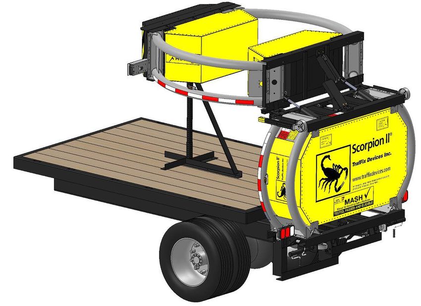
This Page is Intentionally Left Blank

                                P/N 13082 Revision B Dated 10/23/2018 i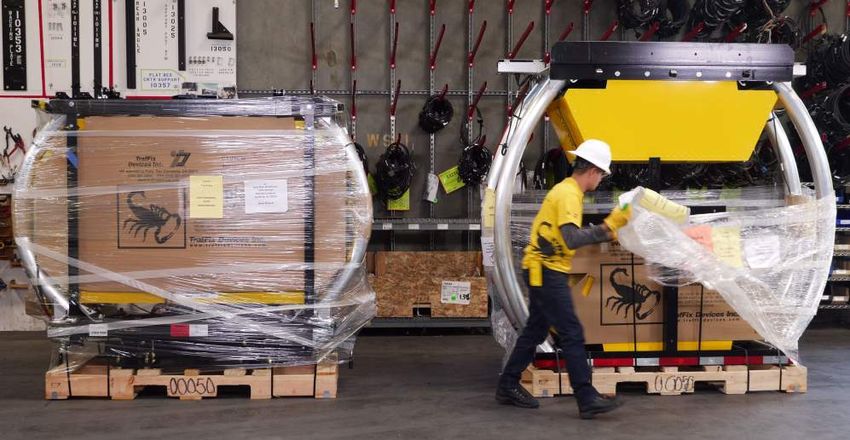
Scorpion II® 10000 TMA
         Introduction to Assembly and Mounting Instruction Guide

                                             160 Avenida La Pata
                                           San Clemente, CA 92673
                             www.traffixdevices.com orders@traffixdevices.com

          Important: These instructions pertain only to the assembly and mounting of the Scorpion II
   !      10000 Truck Mounted Attenuator (TMA) Model C TL-3. These instructions are only for the
          assembly of the models and/or accessories cited in each section. Any deviation from the
          models and accessories shown would require consultation with the appropriate highway
          authority engineer and/or certified TrafFix Devices, Inc. representatives. Contact information
          of these representatives can be found on the last page of this manual (Pg.63).

Proper Installation of the Scorpion II Truck Mounted Attenuator (TMA) is essential for proper performance
of the system. For this reason, contacting a TrafFix Devices, Inc. Certified Attenuator Installer for assistance
in mounting the system is recommended. Contact TrafFix Devices, Inc. to obtain a list of Certified Installers
in the area. Please read this manual in its entirety before assembling, installing, or operating the Scorpion II
TMA. The information in this Manual supersedes all previous versions and manuals, with updated
illustrations and other information available at time of printing; however; TrafFix Devices, Inc. reserves the
right to make changes at any time. For any questions on proper Installation and Operation of the
Scorpion, please contact us at (949) 361-5663.

           Important: This manual applies to the Scorpion II® Truck Mounted Attenuator by TrafFix
  !        Devices, Inc. It pertains only to the models referenced herein. It requires that all Assembly,
           Mounting, Service and Repair parts be Genuine Scorpion parts that have not been modified or
           repaired from the original in any way, unless with prior knowledge, consultation and approval
           by TrafFix Devices, Inc. Engineering.

                                                                          P/N 13082 Revision B Dated 10/23/2018 ii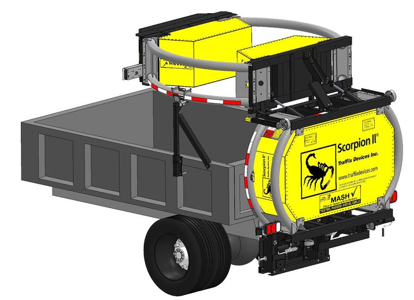
Table of Contents
                                                                                             Page

Section 1   Limitations and Warnings ……………………………………………………………………………………….                        1
            Operating Instructions………………………………………………………………………………………….... 2-3
            Safety Instructions & Precautions……………………………………………………………………………                    4
            Notes………………………………………...…………………………………………………………………………..                             5
            TMA Model C Parts List- Major Components…………………………………………………………..                 6-7
Section 2   Assembly of TMA Model C…………………………………………………………………………………..…                         8
              Pre-Assembly Checklist/Scorpion II Registration………………………………….……………… 9
              Remove Packaging/Tail Light & Side Marker Light Inspection…………………………… 10-11
              Recommended* Assembly Tools………………………………………………………………….…..                        12
              Strut Assembly………………………………………….………………………………………………..…..                        13-17
              Cartridge Assembly…………………………………...…………………………………………………...                      18-20
              TMA Model C: Strut to Cartridge Assembly……………………….…………………………….. 21-28
              Hydraulic Pump Assembly/Parts List…………………………….…………...…………………...               29-30
Section 4   Standard Truck Mounting Installation……………………….…………………………………….……                   31
              Standard Flatbed Truck Mounting Installation…………………………………………….…… 32-36
              Dump Truck Mounting Installation……………………………………………...………………….. 37-40
              Installing the Fast-Trak SwiftConnect™ to the TMA………………………………………....            41
              Fast-Trak SwiftConnect™ Configuration 1…………………………………………………….....              42-43
              Fast-Trak SwiftConnect™ Configuration 2…………………………………………………….....               44
              Fast-Trak SwiftConnect™ Configuration 3…………………………………………………….....               45
              Fast-Trak SwiftConnect™ Step-by-Step Mounting Process……………..…………….....         46
Section 5   Support Post Installation……………………………………………………………………………...……...                    47
              Flat Bed Side Support Installation…………………………..……………………………...…….… 48-52
              Center Support Installation……………………………………………………………………………… 53-55
              Dump Truck Side Support Installation………………………………………………………………. 56-60
Section 6   Limited TMA Warranty/ Notes…………………………………………………….……………………..... 61-62
            TrafFix Devices, Inc. Contact Information…………………………………………………………......            63

                                                             P/N 13082 Revision B Dated 10/23/2018 iii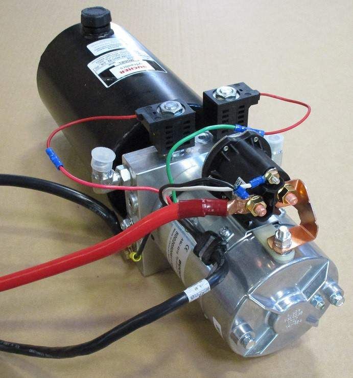
Limitation and Warnings
TrafFix Devices Inc. (TDI), in compliance with the Manual for Assessing Safety Hardware
(MASH) recommended procedures for the Safety Performance of Highway Features. TDI
contracts with ISO accredited testing facilities to conduct crash tests, evaluation of tests, and
submittal of results to the Federal Highway Administration for Eligibility for Federal-Aid
Reimbursement. The Scorpion II Truck Mounted Attenuator (TMA) system was tested to meet
the safety evaluation guidelines of MASH. The Scorpion II has been tested at TL-3 (62.1 mph/
100 km/hr) speed impact conditions. These tests are intended to evaluate product performance
by simulating those impacts outlined by MASH involving a range of vehicles on the roadways,
from cars with an approx. weight of 2425 lbs [1100 kg] to trucks with an approx. weight of
5004 lbs [2270 kg]. The Model C TMA is a TL-3 tested device capable of decelerating and
stopping the light and heavy weight vehicles 2425 lbs [1100 kg] and 5004 lbs [2270 kg] in
accordance with the criteria of Tests 3-50, 3-51, 3-52, and 3-53 for TL-3 (62.1 mph/ 100 km/
hr) FHWA Eligibility. Reference FHWA Eligibility letter CC-132. Additionally, the Scorpion II
TMA was tested to meet the requirements of TD 49/07. These tests are based on the Requirements for
Lorry Mounted Crash Cushions from the Highways England Road Ministry. The Scorpion II TMA is
accepted for various speed levels as shown in TL3.UK: 110 km/h [68.3 mph]. These specified tests
are not intended to represent the systems performance when impacted by every vehicle type or
every impact condition existing on the roadway. This system is tested only to the test matrix
criteria of MASH and TD 49 UK. TrafFix Devices does not represent nor warrant that the
results of these controlled tests show that vehicle impacts with the products in other conditions
would necessarily avoid injury to person(s) or property. Impacts that exceed the system’s
specifications may not result in acceptable crash performance as outlined in MASH; relative to
structural adequacy, occupant risk, and vehicle trajectory. TDI expressly disclaims any warrant
or liability for injury or damage to person(s) or property resulting from any impact, collision, or
harmful contact with products, other vehicles, or nearby hazards or objects by any vehicle,
object or person, whether or not the products were installed by third parties. The Scorpion II
TMA system is intended to be assembled, delineated, and maintained in accordance with
specific State and Federal guidelines. TDI offers a reflective delineator panel for its TMA line
of products. However, the material is only intended to supplement delineation required by the
Department of Transportation’s “Manual on Uniform Traffic Control Devices” (MUTCD). The
appropriate highway authority approved engineer should be careful to properly select,
assemble, and maintain the product. Careful evaluation of the speed, traffic direction, and
visibility are some of the elements that require evaluation for the proper selection of a safety
appurtenance by the appropriate specifying highway authority.

                                                                    P/N 13082 Revision B Dated 10/23/2018 1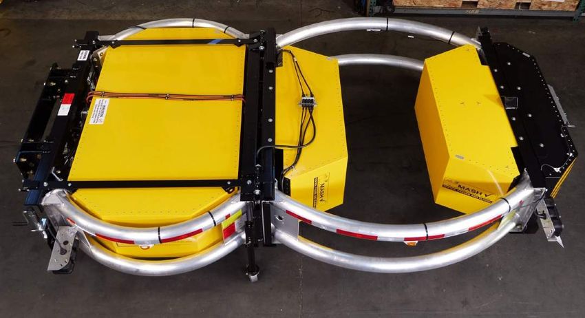
Operating Instructions
Proper Operation includes knowledge of TMA use in Work Zones, both Moving and Stationary, including
the proper spacing, to allow for “roll-ahead”. Before use, the Operator should have prior knowledge/
discussion of the Work Zone in which the TMA will be deployed and that the TMA model used has been
tested to Test Level 3 = 100 kph/62 mph. TMA’s should only be operated by individuals properly trained
in their use in work zones.

Pre-Use Inspection
      1. Walk around the unit inspecting for damaged, loose, or missing bolts, pins, cotter pins and safety
         snaps.
      2. Inspect for damage to the energy absorbing modules and aluminum tubes, checking for deep
         gouges, deep scratches, warping, or cracking.
      3. Inspect the steel structure for damage, looking for warping, cracks, breaks or other damage.
      4. Inspect all lights for proper operation (including arrow/message board if applicable).
      5. Cycle the unit from stowed to deployed and back to stowed position (see directions below),
         ensuring proper sequence and function (including arrow/message board lift system if attached) pay
         close attention for any binding or “slop” during operation and that the alarm is functioning
         properly.
      6. Check road clearance of TMA in deployed mode, to ensure it is in specification (12 inches ±1 inch).
      7. Ensure that retroreflective sheeting is in place and meets requirements for job.
      8. When cycling the TMA up and down, check the lockout arm (between the cartridge and strut) for
         proper motion and alignment. When in the stowed position, the two pivoting sections of the lock-
         out arm should form a straight line.
      9. Check visually for hydraulic leaks.
     10. Check to ensure that there are no loose items on the truck that can become a projectile during an
          impact.
     11. Make sure items in the cab of the vehicle are secure and cannot come loose and become a
          projectile should an impact occur.
     12. Adjust the headrest properly for the driver of the vehicle.
     13. Any deficiencies should be corrected before use.

                                                                               MUST BE FULLY POWERED DOWN
                                                                                  FOR TRAVEL 0 TO 60 MPH

                                                                               MUST BE FULLY POWERED DOWN
                                                                                FOR DEPLOYMENT 0 TO 30 MPH

                                                                       P/N 13082 Revision B Dated 10/23/2018 2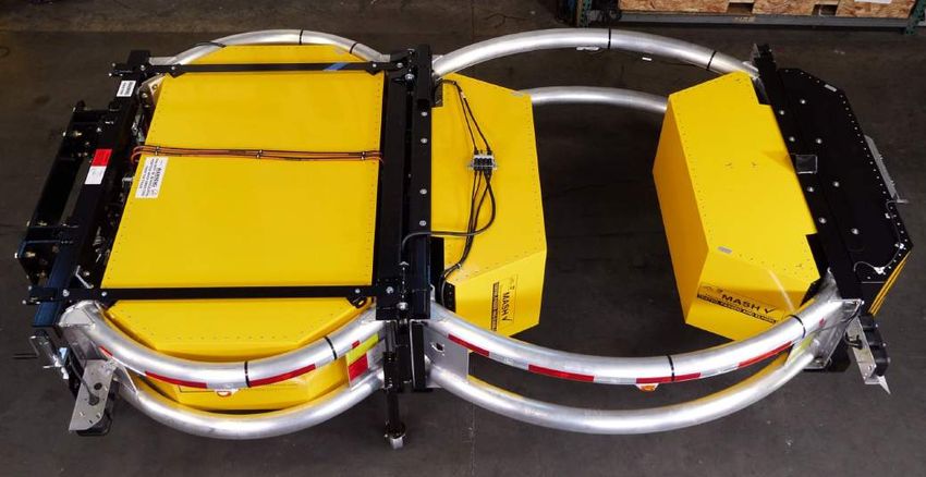
To Raise (“Store”) the Unit for Transport

       1. Ensure that both the truck bed and area above the rear of the host vehicle is clear.
       2. Locate the desired control box, either the in-cab controller (if installed) or the plug-in. If using the
          plug-in, and it is not already plugged in, plug it into the socket on the TMA near the rear
          passenger side of the truck.
       3. Push the “Up” button on the chosen controller and hold until the unit makes contact with the
          support posts. Be sure to avoid the pinch points around cartridge to strut hinge and the pivot
          point at the strut to truck connection. If an Arrow/Message Board Lift System is installed, be
          sure it cycles to the down position before the TMA raises.
       4. Continue to hold the Up button until the Scorpion slides forward 1-2 inches on the support post(s)
          and for 4 seconds after it has stopped moving. This ensures the hydraulic system is at the proper
          pressure to hold the TMA tight against the cradle which will save wear and tear or possible
          damage to the unit.
       5. If the unit is to be transported, ensure that the drop jacks are fully retracted and pinned and that
          the swivel jacks are fully retracted and rotated to the stored and locked position.
       6. If using the plug-in controller unplug and store in the cab.

To Lower (“Deploy”) the Unit for removal or Use

       1. Ensure that both the area above and to the rear of the host vehicle is clear.
       2. Plug in the controller (see #2 above) or locate the in-cab controller (if installed).
       3. If the unit is being removed, the swivel jacks should be rotated to the deployed position and the
          drop jacks lowered and pinned to the correct height. If the unit is being deployed for use, all
          jacks should remain in the stored position.
       4. Being careful to avoid the pinch points, push the “Down” button until the TMA is fully unfolded
          and the rear box has stopped moving and the tail/ICC light covers have deployed.
       5. Continue to hold the Down button for 4 more seconds after the Arrow/Message Board Lift System
          (if attached) or the TMA has stopped moving. This will ensure the TMA is fully deployed and the
          hydraulic system is at the proper pressure to hold it in position.
       6. Make sure the Arrow/Message Board is displaying the proper message.

Note: TMA must be in the stowed position for travel to and from the Work Zone

Important: It is recommended that the unit not be deployed, used, or stowed for transport, while the host
vehicle is travelling at speeds above 30 miles per hour. If your application makes this necessary, please see
the “Severe Duty Note” in the “Maintenance Intervals and Pre-Use Inspection”. As described in the
procedure above, always ensure the area above and to the rear of the bed of the truck is clear before
deploying or stowing the Scorpion.

                                                                           P/N 13082 Revision B Dated 10/23/2018 3
SAFETY INSTRUCTIONS & PRECAUTIONS
A. Before attempting to install or operate the Scorpion II 10000 Series Truck Mounted Attenuator (TMA) this manual
   should be read and understood. Those areas with warnings or cautions should be carefully followed.
B. Before raising or lowering the TMA the operator should check that the area around the TMA is clear and that
   personnel are not in or near the area.
C. Before operation on the roadway, check all 1” diameter pins and bolts at the back-up and hinge areas for tightness
   and excessive wear. Also, check that all cotter pins are in place.
D. Check that the two drop jacks are fully retracted and that the safety pins are in place. Also, check that the crank
   jacks are fully retracted and rotated to the up and locked
   position.

E. For correct operation of the TMA in the use mode (fully extended in the horizontal
   position), the TMA should be 12" ± 1” above the ground and horizontal to the roadway.
F. The responsible agency for the truck should check that the following specifications are met: The truck should weigh
   a minimum of 15,000 lbs. If the truck is ballasted, the ballast should be properly anchored to the truck frame to
   prevent movement during an impact. The truck should be equipped with proper operator safety equipment such
   as seat belts, headrest, etc.
G. Before disconnecting the TMA from the truck, make sure the TMA is in the horizontal
   position with all jack fully deployed

                                              Special Warnings
1. After a vehicle impacts the TMA, do not drive the truck with the damaged TMA. Remove the TMA at the backup
   and have the TMA transported back to the maintenance yard.
2. Check the TMA model to make sure that the posted speed matches the TMA
   capacity.
       Model C = TL-3 = 100 kph. (62 mph)

                                                                                 P/N 13082 Revision B Dated 10/23/2018 4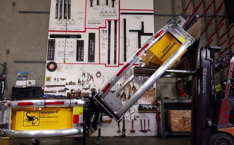
Notes:

         P/N 13082 Revision B Dated 10/23/2018 5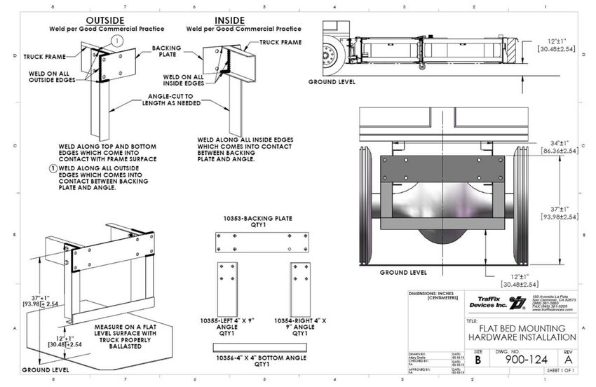
Scorpion II Model C TL-3
                                          Major Components

P/N 13082 Revision B Dated 10/23/2018 6
Scorpion II 10000 TMA Model C Parts List - Major Components
Item # Part # Item Description QTY/TMA
10200T Strut Tube Weldment 2
1 10200TL-KIT Strut Tube Assy, LH, Includes: C-Tape, Warning Labels, Side Marker Bracket Installed 1
10200TR-KIT Strut Tube Assy, RH, Includes: C-Tape, Warning Labels, Side Marker Bracket Installed 1
2 11400D Module D, Absorbing Scorpion II 1
3 10204 Energy Absorber Bracket 2
4 10300 Backup, Powder Coated Black 1
5 10300E Rear Diaphragm, Strut, Powder Coated Black 1
6 10118 Tension Strap Set, Powder Coated Black, Includes Hardware 1
7 11800 Lockout Arm, Powder Coated Black, Includes Hinges and Hardware 1
8 11551 Reinforcing Bar, Powder Coated Black 8
9 10351 Hydraulic Bracket, RH 2
10 10352 Hydraulic Bracket, LH 2
11 10750 Drop Jack Bracket, Universal, Powder Coated Black 2
12 10725 Drop Jack w/ 6” Caster 2
13 10701MNJ Heavy Duty Swivel Jack w/ 6” Caster 2
14 10600J Hydraulic Hose Kit, Scorpion II 1
11010 Hydraulic Power Unit, 12V, Field Service Replacement 1
15
11011 Hydraulic Power Unit, 24V, Field Service Replacement 1
16 11200A Hydraulic Cylinder, 3” Bore, 8” Stroke, Fittings Installed 2
17 11617A Hydraulic Cylinder, 2-1/2” Bore, 8” Stroke, Fittings Installed 2
18 11812A Hydraulic Cylinder, 2” Bore, 4” Stroke, Fittings Installed 1
10508C-LED Strut Tail Light Assy, LH, 10-30 Volt LED, Color Pattern: Red/Red/White
19 10504C-LED-RYR Strut Tail Light Assy, LH, 10-30 Volt LED, Color Pattern: Red/AmberRed 1
10504C-LED-YRW Strut Tail Light Assy, LH, 10-30 Volt LED, Color Pattern: Amber/Red/White
10516C-LED Strut Tail Light Assy, RH, 10-30 Volt LED, Color Pattern: Red/Red/White
20 10505C-LED-RYR Strut Tail Light Assy, RH, 10-30 Volt LED, Color Pattern: Red/AmberRed 1
10505C-LED-YRW Strut Tail Light Assy, RH, 10-30 Volt LED, Color Pattern: Amber/Red/White
21 10518 Junction Block 2
22 10507C Motion Alarm, 10-30 Volt 1
23 10573 Side Marker Light, Amber, 10-30 Volt LED 4
24 10520 Housing, Side Marker Light 4
25 10524 Bracket, Side Marker Light 4
10100T Cartridge Tube Weldment 2
26 10100L-KIT Cartridge Tube Assy, LH, Includes: C-Tape, Warning Labels, Side Marker Bracket Installed 1
10100R-KIT Cartridge Tube Assy, RH, Includes: C-Tape, Warning Labels, Side Marker Bracket Installed 1
27 11400C Module C, Energy Absorbing, Scorpion II 2
28 10400A Module A, Energy Absorbing, 4” Yellow Avery MVP Sheeting 1
29 11300F Front Diaphragm, Cartridge, Powder Coated Black 1
30 11300H Rear Diaphragm, Cartridge, Powder Coated Black 1
31 11327 Bottom Angle, Cartridge, Powder Coated Black 1
32 10465 Top Angle, Cartridge, Powder Coated Black 1
33 10122 Vertical Support Angle, Powder Coated Black 2
10508B-LED Cartridge Tail Light Assy, LH, 10-30 Volt LED, Color Pattern: Red/Red/White
34 10504B-LED-RYR Cartridge Tail Light Assy, LH, 10-30 Volt LED, Color Pattern: Red/AmberRed 1
10504B-LED-YRW Cartridge Tail Light Assy, LH, 10-30 Volt LED, Color Pattern: Amber/Red/White
10516B-LED Cartridge Tail Light Assy, RH, 10-30 Volt LED, Color Pattern: Red/Red/White
35 10505B-LED-RYR Cartridge Tail Light Assy, RH, 10-30 Volt LED, Color Pattern: Red/AmberRed 1
10505B-LED-YRW Cartridge Tail Light Assy, RH, 10-30 Volt LED, Color Pattern: Amber/Red/White
36 10500B ICC Bar Light Assy w/ Cover Flap 1
37 10914 Conspicuity Tape, 11” Red/ 7” White, Sold by the Inch, Sturt Tube Requires 48” 96
38 10914 Conspicuity Tape, 11” Red/ 7” White, Sold by the Inch, Cartridge Tube Requires 72” 144
P/N 13082 Revision B Dated 10/23/2018 7Assembly of TMA Model C
P/N 13082 Revision B Dated 10/23/2018 8Pre-Assembly Checklist
Initial Inspection:
Compare the Packing List with the original order to ensure all items have been delivered. Should any damage be found,
or any items missing, contact the freight company as well as a TrafFix Devices representative as soon as possible.
Scorpion II Registration
1. Once unpacked, ensure that the TMA Serial Number matches with the number shown on the Packing List and the
pallet. Once confirmed that they are the same, record the Serial Number below with all the serialized components to
retain for personal records. TrafFix Devices, Inc. will require this Serial Number for any possible repairs, warranty
claims, and maintenance records.
Identify Serial Number for Scorpion II Truck Mounted Attenuator:
Cartridge
Strut
All Serial Numbers must coincide with each other
Module A Serial Number:_______________
Module B Serial Number:_______________
Module C Serial Number:_______________
Module D Module D Serial Number:_______________
Serial Number
Module C
Serial Number
Module A
Serial Number
Sample of
Module Serial Number
Module C
Serial Number
Strut Palletized Cartridge Palletized
P/N 13082 Revision B Dated 10/23/2018 9Removing Packaging for Inspection
2. Observe the warning signs before unwrapping.
• Remove plastic wrap and cardboard with utility knife.
P/N 13082 Revision B Dated 10/23/2018 10Unwrap and Inspect: Tail Lighting and Side Marker Lights
3. Remove all cardboard from lights and
inspect for damage.
Side Marker:
Cartridge
Tail Lighting:
Strut
P/N 13082 Revision B Dated 10/23/2018 11TMA Model C (TL-3) Assembly
1. IMPORTANT: Before beginning Assembly, please read and review the Installation Section of this manual, paying close
attention to the checklist at the beginning of the section.
2. Inspect the two pallets containing the Cartridge (right) and the Strut (left), shown in Figure 1, for shipping damage and
completeness against the packing list. If there is anything missing or not complete, contact a TrafFix Devices
representative as soon as possible.
3. WARNING: TOP HEAVY– Indicates to move pallets with extreme caution. The use of a forklift is preferred when handling
pallets. All personnel should be kept clear when the pallets are being moved.
4. Remove the shrink-wrap from the pallets using a utility knife. Caution: Be careful not to cut any wires or parts!
When Cutting Bands,
Pieces from Top will Fall
STRUT PALLETIZED CARTRIDGE PALLETIZED
Figure 1
Recommended* Assembly Tools
1. Hammer
2. Tapered Pry Bar
3. Tape Measure
4. 12” Crescent Wrench
5. 1/2” Drive Socket Wrench
6. 1/2” Drive Socket (1-7/16”)
7. Open End Wrenches (1-7/16”, 3/4”, 7/16”)
8. 3/8” Drive Socket Wrench
9. 3/8” Drive Socket (7/16”, 3/4”)
10. Allen Wrench
11. Wire Cutter/Crimper
12. Floor Jacks or Stands (2 Ea.)
13. Forklift
*More or less tools may be needed.
P/N 13082 Revision B Dated 10/23/2018 12Strut Assembly Overview
1. Remove the steel bands holding the Strut to the
pallet.
2. Lift the Strut off the pallet using a forklift.
3. Remove mounting brackets from the pallet.
4. Reposition the Strut on the edge of the pallet.
5. Lower drop jacks so that the yellow paint is not
showing.
6. Move the lifting straps towards the Back-up of the
Strut and lift, using a forklift, until the unit is level.
7. Lower the swivel jacks so the Strut is no longer
supported by the forklift.
8. Remove the clevis and hair pins from the hydraulic
cylinder.
P/N 13082 Revision B Dated 10/23/2018 13Strut Assembly
1. Attach two (2) lifting straps to the Strut Diaphragm. The lifting straps must be positioned at an equal distance
from the center to maintain stability when lifted. Each strap must have a minimum of 1500lb or greater load
capacity. WARNING: Do NOT tip the strut when attaching the lifting straps.
Lifting Straps
2. Cut and remove the steel bands that hold the Strut to the pallet.
Steel Bands
3. Using a forklift, lift the Strut off of the pallet. CAUTION: Be sure the drop jacks are facing the forklift before lifting
the strut. Once the Strut is safely off of the pallet, remove the mounting brackets that are on the pallet.
Mounting Brackets
P/N 13082 Revision B Dated 10/23/2018 14Strut Assembly
4. Position the strut on the edge of the pallet then slowly start lowering the Strut.
5. Once the drop jacks can safely be reached, do not lower the Strut any further. Do not let the lift straps slide off
the forklift blades. Extend the drop jacks so that the yellow painted edge is aligned with the bottom of the drop jack
mounting bracket. Secure the drop jacks in place with the safety snap. Continue to lower the strut until the drop
jacks are stable on the ground.
P/N 13082 Revision B Dated 10/23/2018 15Strut Assembly
6. Remove the lifting straps from the Diaphragm and place them on the Back-up of the Strut. Lift the Strut until it is
level.
7. Rotate and lower the swivel jacks so that the Strut is level. The Strut should no longer be supported by the forklift
once the swivel jacks are deployed.
P/N 13082 Revision B Dated 10/23/2018 16Strut Assembly
8. Cut and remove the zip ties that hold the hydraulic cylinders to the Strut. Remove the hair pins and clevis pins from
both cylinders. *Clevis pins and hair pins are needed later on in assembly. Once the hydraulic cylinders are free of
the strut, grab the end of the cylinder and lift until the cylinder is fully extended.
Zip Tie
Hair Pin
Clevis Pin
Hydraulic Cylinder
P/N 13082 Revision B Dated 10/23/2018 17Cartridge Assembly Overview
1. Cut and remove Steel bands and cardboard from the
Cartridge.
2. Remove Module A.
3. Unbolt the junction box from Module C.
4. Remove Module C from the Cartridge frame.
5. Open parts box and confirm contents.
6. Place a piece of cardboard on the forklift to prevent damage
to Module C.
P/N 13082 Revision B Dated 10/23/2018 18Cartridge Assembly
1. Cut the Steel bands that are holding the components to the Cartridge. One person should be holding the
components in place, while another person cuts the bands. WARNING: Watch for falling components when cutting
the Steel Bands. Remove the components and the cardboard from the Cartridge.
Safety Bands
2. Remove Module A from the Cartridge.
Module A
Module C
3. Unbolt the junction box and cables from Module C.
P/N 13082 Revision B Dated 10/23/2018 19Cartridge Assembly
4. Remove Module C from the Cartridge frame and set it aside for later use. Cut and remove the Steel bands that hold
the Cartridge frame to the pallet.
5. Open the parts box and confirm the contents. (If there are any parts missing, document it and inform a TrafFix
Devices Representative immediately.) Take out the two clevis pins and set them aside for later use.
Clevis Pins
6. To prevent paint on Module C from getting damaged, place a piece of cardboard on the blades of the forklift. Use
the forklift to raise the Cartridge frame off of the pallet.
Module C
P/N 13082 Revision B Dated 10/23/2018 20TMA Model C: Strut to Cartridge Assembly Overview
1. With a forklift, align the hinges of the Cartridge to the hinges of the Strut.
2. Connect the Strut and Cartridge using hinge pins, with washers.
3. Secure hydraulic cylinders.
4. Attach the lockout arm.
5. Lower the Cartridge.
6. Install Module C.
7. Secure junction box, clamp, and connecting power cable.
8. Install Module A.
9. Install the ICC Bar Light Cable.
P/N 13082 Revision B Dated 10/23/2018 21TMA Model C: Strut to Cartridge Assembly
1. Cut zip tie holding the power cable that is attached to the Strut. Set the power cable aside for later use.
2. Insert the clevis pin, with a washer, into the hinges connecting the Strut to the Cartridge. Tap the pin into position if
necessary. Secure the clevis pin with a cotter pin.
P/N 13082 Revision B Dated 10/23/2018 22TMA Model C: Strut to Cartridge Assembly
3. Secure the hydraulic cylinders to the Cartridge frame using the clevis pins. Secure the clevis pins with hair pins.
P/N 13082 Revision B Dated 10/23/2018 23TMA Model C: Strut to Cartridge Assembly
4. Bolt the lockout arm on the Strut, with washers, to the Cartridge. Using an “impact gun”, fasten the bolts to the
Diaphragm up to 95 ft-lbs. To ensure the proper orientation of the bolts, the bolt heads must be visible on the
Cartridge side.
Lock out Arm
(attached to Strut)
Lock out Arm Bolted
Onto Cartridge
P/N 13082 Revision B Dated 10/23/2018 24TMA Model C: Strut to Cartridge Assembly
5. Slowly lower the Cartridge with the forklift until the TMA is level.
P/N 13082 Revision B Dated 10/23/2018 25Module C Installation
6. Install Module C.
A. Lift Module C into position on the Cartridge and secure with washers and Allen head bolts.
B. Use Threadlock adhesive on all bolts and tighten to a minimum of 20 ft-lbs.
7. Secure the junction box and bolt the clamp on top of Module C. Once secure, connect the power cable to the
junction box.
Junction Box
Clamp
Power Cable
P/N 13082 Revision B Dated 10/23/2018 26Module A Installation
8. Install Module A.
A. Lift Module A into position on the Cartridge and secure with bolts and washers.
B. Use Threadlock adhesive on all bolts and tighten to a minimum of 20 ft-lbs.
9. Cut the zip tie that is holding the electrical cable and attach it to the cable that is located in the back of Module A.
Secure the cables to the top of Module A using zip ties.
Zip ties
P/N 13082 Revision B Dated 10/23/2018 27Complete Assembly of Model C
STRUT CARTRIDGE
Module D Module C Module A
Module C
P/N 13082 Revision B Dated 10/23/2018 28Hydraulic Pump Assembly
1. Fill the reservoir on the hydraulic pump with three gallons of Automatic Transmission Fluid (ATF) and attach the
electrical wires (minimum gauge size of #1 battery cable for both the positive and negative hydraulic motor
connections) to the motor cables. Push the “up” button on the yellow controller to raise the TMA to its stored
position.
2. Fill the reservoir a second time with two more quarts. Cycle the system two times waiting 3 minutes between
cycles to remove the air bubbles from the system. Fill the rest of the reservoir with two quarts of hydraulic fluid.
3. Roll the TMA back to the host vehicle and bolt the four hydraulic angle brackets to the backing plate first, before
installing the TMA onto the host vehicle. Use full manual torque with a breaker bar and a wrench to fasten the
brackets to the backing plate.
4. Finish with the TMA in the deployed position to mount onto the host vehicle. Terminology for the hydraulic pump
and the motor are illustrated below:
Fill Cap Reservoir
List of Acceptable Hydraulic Fluids
• Automatic Transmission Fluid (ATF)
• Cold Weather Hydraulic Fluid
Motor
Connection to Battery (-) Connection to Battery (+)
P/N 13082 Revision B Dated 10/23/2018 29Hydraulic Pump Parts List
5
1A 1B
3A 3B 2A 2B
4A 4B
Item # Part # Item Description QTY/TMA
1A 11010 12 Volt Motor w/ Hydraulic Pump - Complete 1
1B 11011 24 Volt Motor w/ Hydraulic Pump - Complete 1
2A 11020-12 Valve w/ 12V Coil, controls "up" 1
2B 11020-24 Valve w/ 24V Coil, controls "up" 1
3A 11021-12 Valve w/ 12V Coil, controls "down" 1
3B 11021-24 Valve w/ 24V Coil, controls "down" 1
4A 11024 12 Volt Solenoid 1
4B 11025 24 Volt Solenoid 1
5 11012NJ-CAP Filler Cap for TMA Motor 1
P/N 13082 Revision B Dated 10/23/2018 30Standard Truck
Mounting Installation
Flat Bed Mount Dump Truck Mount
Fast Trak Swift Connect Mount
P/N 13082 Revision B Dated 10/23/2018 31P/N 13082 Revision B Dated 10/23/2018 32
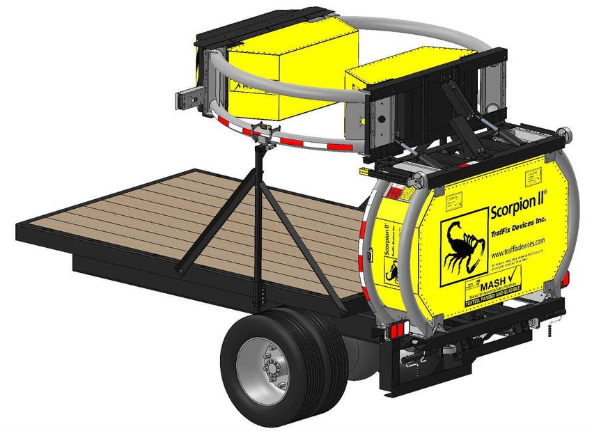
Standard Flatbed Truck Mounting Installation
                                          Truck Installation Model C
Before attempting to install the TMA to a host vehicle truck, ensure that the truck meets the following criteria: Truck
weight specifications vary from state to state; however, it is recommended that the truck weighs a minimum of 15,000
lbs.
Adding ballast can affect the truck bed height, so it is preferred to ballast the truck before attaching the TMA. Check
the truck frame to ensure that it is structurally sound and rust-free. Also, check the amount of frame extension in back
of the spring brackets – a minimum of 10” is needed. Check that the bed of the truck does not extend beyond the back
of the frame more than 4” . This is necessary for vertical clearance of the TMA. Check the frame for a cross tie plate
connecting one side to the other if the frame extends to the rear more than expected. It is preferred to keep the frame
from extending more than 24” from the back of the spring support bracket. Also check the height of the truck side
gates. These should be less than 8’ 6” from the ground to allow clearance if the double 90° tilt is used.

1. The truck frame consists of two C-channels spaced ap-
proximately 34” apart. Grind the inside and outside of the
ends of the frame, as shown in this figure (right), in prepa-
ration for tack welding process. The frame should be
square from side to side. Use a carpenter’s square tool or
any other square device to verify that the frame is indeed
level and straight. Also measure the distance from the
frame ends to the back of the spring brackets.

                                                                                 10”

2. Mount the Backing Plate (P/N: 10353) onto the
backup of the TMA as shown in this figure (right).
Mounting the backing plate onto the TMA will
simplify the alignment process when mounting the
backing plate onto the truck frame of the host
vehicle.

                                                                               P/N 13082 Revision B Dated 10/23/2018 33
3. With the assembled TMA in the deployed position, deploy and adjust all four jacks on a flat-leveled surface (shown
in the figure below) to a height that measures approximately 14 1/2”- 15” from the underside of the TMA to the flat
surface. This height is to account for the settling of about 2” that the truck will experience after the TMA is mounted
onto the frame when the jacks are raised in their stored position. It is essential to measure and verify the recommend-
ed height of 14 1/2”-15” on both sides of each diaphragm. The figure below also illustrates the locations of where that
specified height should be measured.
4. With the jacks deployed, roll the deployed TMA to the rear of the host vehicle and align the TMA centerline with
the vehicle, as shown in the following figure. The backing plate that is bolted onto the TMA (See step 2) should be
flush with the ends of the truck frame.
P/N 13082 Revision B Dated 10/23/2018 345. After proper confirmation of the backing plate being level and 90° to the horizontal surface, deploy the drops jacks
and unbolt the TMA from the backing plate that is already tacked onto the host vehicle. Fully weld the backing plate on
both the inside and outside of the frame rails. Proper welding locations are specified in the figure below:
6. Position the 9” x 4” vertical angles with C-clamps on to the side of the frame as shown in first figure (bottom left). No-
tice there is a left and right side vertical angle and the flanges should be positioned toward the rear of the truck. Four
holes are located in the angle for bolting to the frame (refer to middle figure). Center the holes vertically on the frame
and drill/burn 4 holes in the frame on both sides. Also, drill/burn 2 holes on the angle to align with the outermost holes
of the backing plate as shown in the middle figure as well. Bolt the vertical angles onto the frame with the 1” bolts as
shown in the last figure (bottom right).
P/N 13082 Revision B Dated 10/23/2018 357. Weld the angles in place at the rear of the angle. Refer to the figure below for proper welding locations.
(DRIVER SIDE)
8. Install the lower bottom angle (P/N: 10356) and fully weld the angle in place. Refer to the following figure for prop-
er welding locations.
9. Proceed to the Section titled “Support Installation” and follow the Installation that matches the type of Supports
you ordered.
P/N 13082 Revision B Dated 10/23/2018 36Dump Truck Mounting Installation
Installation of Extension Frame
Before attempting to install the TMA to a host vehicle truck, ensure that the truck meets the following criteria: Truck
weight specifications vary from state to state; however, it is recommended that the truck weighs a minimum of 15,000
lbs.
Adding ballast can affect the truck bed height, so it is recommended to ballast the truck before attaching the TMA.
Check the truck frame to ensure it is structurally sound and rust-free. Also, check the amount of frame extension in
back of the spring brackets – a minimum of 4” is needed. Verify that the bed of the truck does not extend beyond the
back of the frame more than 15”. This is necessary for vertical clearance of the TMA when in the stored position.
Ensure that the truck side gates are measured at a maximum height of 8’ 6” from the ground to allow clearance if a
Model C TMA is being used and is in the stored position.
1.The truck frame consists of two C-channels spaced
approximately 34” apart. Dump trucks often have a ½”
thick plate welded across the back of the frame. A plate
must first be installed before the extension frame can be
mounted if a plate is not present. Grind the inside and out-
side edges of the frame, as shown in this figure (right), to
prepare for a weld. Verify that the frame is square from
side to side, using a carpenter’s square tool or any other
square device. Also measure the distance from the frame
ends to the back of the spring brackets.
Figure 1
10”
2. A backing plate (33” x 10”) should be centered on
the back of the truck frame. Note where the frame
will be welded to the plate and grind the plate in this
location. Tack weld the rear plate into position and
make sure that the rear plate is positioned vertically
at 90° to horizontal. Continue by welding the inside of
the frame end to the plate.
10”
P/N 13082 Revision B Dated 10/23/2018 373. The extension frame comes with the right and left vertical tubes bolted in place in the right and left frame sections
as shown in the first figure below. For ease of attachment to the truck, mount the extension frame to the TMA , as seen
in the below second figure, and roll the TMA with the extension frame to the back of the truck,. Make sure the TMA is
at 14 ½”- 15” in height, measured from the underside of the TMA to the ground. This height is to account for the
settling of about 2” that the truck will experience after the TMA is mounted onto the frame when the jacks are raised
in their stored position.
EXTENSION FRAME SHOWN
WITHOUT SPLICE PLATES
GROUND
P/N 13082 Revision B Dated 10/23/2018 384. Once the TMA is rolled towards the back of the host vehicle, tack weld the tubes in place at the outermost and
innermost four corners where the tubes touch the frame. This image below illustrates ideal tack welding locations to
hold the tubes in place.
5. Remove the four 1” bolts from the vertical tubes and roll the TMA rearward to pull the extension frame free from
the vertical tubes. Fully weld the tubes in place on all four sides where the tubes touch the frame and the back plate.
Refer to following figure for details.
P/N 13082 Revision B Dated 10/23/2018 396. Position the splice plates, as shown here in this figure below, against the sides of the frame and the vertical tubes.
Mark on the plate the position of two holes for ¾” bolts. Drill these holes in the plates and the frame. Weld the edge
of the plate to the vertical tube. The truck frame weld areas should be spray painted to prevent rust.
7. After the splice plates have been welded on the tubes, Install the four ¾” bolts in the designated holes that were
drilled into the plates to reinforce the splice plates as well as the tubes..
8. To reattach the TMA to the truck, either use the 1” bolts supplied or use the T-pins, if the T-pins were purchased as
an option.
9. Proceed to the Section titled “Support Installation” and follow the Installation procedures that match the type of
Supports that were ordered.
P/N 13082 Revision B Dated 10/23/2018 40Installing the Fast-Trak SwiftConnect™
for the
Scorpion Truck Mounted Attenuator (TMA)
(Follow the Directions for the Configuration received)
Configuration 1
Configuration 2
Configuration 3
P/N 13082 Revision B Dated 10/23/2018 41Fast-Trak SwiftConnect™ Configuration 1
(Configuration 1 is for trucks where the back end of the truck has no plate and only the truck frame rails are exposed.)
PN: 11140-06 used for illustration, other lengths are installed in the same way.
Adding ballast can affect the truck bed height, so it is advisable to ballast the truck before attaching the TMA. Check
the truck frame to make sure that it is structurally sound and not rusted. Also check the amount of frame extension in
back of the spring brackets – a minimum of 10” is needed. Check that the bed of the truck does not extend beyond the
back of the frame more than 4” (see Fig. 3). This is necessary for vertical clearance of the TMA. Check the frame for a
cross tie plate connecting one side to the other if the frame extends to the rear more than a few feet. It is preferred to
keep the frame from extending more than 24” from the back of the spring support bracket. Also check the height of
the truck side gates. These should be less than 8’ 6” from the ground to allow clearance if the double 90° tilt is used.
Part number 11141 truck mount comes with a plate to be welded to the truck frame rails. Before fully welding part
number 11141 truck mount to the frame rails, tack in the part to ensure proper alignment and height recommenda-
tions from the ground. Refer to the Scorpion TMA Dump Truck Mount recommendations. Once fully welded, use
Figure 1 below for installation and assembly for all of the components for Configuration 1.
1. The truck frame should be two c-channels spaced 34” apart. Start by grinding the inside and outside of the end of
the frame to prepare for a weld. Make sure that the frame is square from side to side by measuring the same distance
from the frame ends to the back of the spring shackles.
Figure 1: Exploded and assembled view of Configuration 1.
2. The rear plate (42” x 22”) (shipped with the strut) will be centered on the back of the truck frame and the bottom of
the Truck Mount Frame will be 16-1/4” above the ground. The truck will settle about ½” after installation of the TMA
and this is accounted for. REMEMBER THAT THE TRUCK MUST BE BALLASTED BEFORE WELDING THE REAR PLATE ON
THE TRUCK FRAME. Note where the frame will be welded to the plate and grind the paint off the plate in this location.
P/N 13082 Revision B Dated 10/23/2018 42Truck Mount Plate Rear Plate and Frame Rails will vary
Truck Mount Frame
(Rear Plate) depending on height of frame rails
Height from the Truck Weld Truck Mount Be sure that Truck Mount
Mount Frame to the Frame to Truck Mount Plate is welded 90 degrees
ground. Plate to Truck Frame Rails
Figure 2: General information on the Fast-Trak/SwiftConnect.
3. Tack weld the rear plate into position and make sure that the Truck Mount Frame is at 16-1/4” above ground, is level
across the top, and positioned vertically at 90° to horizontal. Continue by welding the inside and outside frame end to
the plate. Note: If the rear plate cannot be positioned on the truck frame rails to allow the truck mount frame be at 16-
1/4” above ground, then cut the welds between the Truck Mount Frame and the Rear Plate. Position and weld the Rear
Plate first as mentioned above. Then position and weld the Truck Mount Frame to the Rear Plate as mentioned above.
Figure 3: General information on the Fast-Trak/SwiftConnect.
Table 1: Configuration 1 components.
Configuration 1 (PN 11140-06) Components
Part Number Description Quantity
11142-06 TMA Side Mount (FTSC 6”) 1
11141 Mounting Plate w/ Traks (Truck Side Mount) 1
10934-FTSC Hitch T-Pin 2
12058 Round Retainer Locking Pin 2
P/N 13082 Revision B Dated 10/23/2018 43Fast-Trak SwiftConnect™ Configuration 2
Plate already welded on truck
PN: 11145-06 used for illustration, other lengths are installed in the same way.
Figure 4: Exploded and assembled view of Configuration 2.
Configuration 2 is for trucks where the back end of the truck has a sturdy plate already welded to the truck frame rails.
Before fully welding part number 11146 truck mount to the frame rails, tack in the part to ensure proper alignment
and height recommendations from the ground. Refer to the Scorpion TMA Dump Truck Mount for recommendations.
Once fully welded, use Figure 4 above for installation and assembly for all of the components for configuration 2.
Additionally, refer to Step 3 of Configuration 1 for further instructions on positioning and welding PN 11146 to the
Rear Plate.
Configuration 2 (PN 11145-06) Components
Part Number Description Quantity
11142-06 TMA Side Mount (FTSC 6”) 1
11146 FTSC Side Traks (Truck Side Mount) 1
10354 4” x 9” Steel Angle, Right 1
10355 4” x 9” Steel Angle, Left 1
10934-FTSC Hitch T-Pin 2
12058 Round Retainer Locking Pin 2
P/N 13082 Revision B Dated 10/23/2018 44Fast-Trak SwiftConnect™ Configuration 3
Side mounts for truck side
PN: 11155-30 used for illustration, other lengths are installed in the same way.
Figure 5: Exploded and assembled view of Configuration 3.
Configuration 3 is used for applications where an extension is required such as a bed overhang. Before fully welding the
truck mount to the frame rails, tack in the part to ensure proper alignment and height recommendations from the
ground. Refer to the Scorpion TMA Dump Truck Mount for recommendations. Once fully welded, use Figure 5 above
for installation and assembly for all of the components for Configuration 3.
Table 4: Configuration 3 components.
Configuration 3 (PN 11155-30) Components
Part Number Description Quantity
11152-30 TMA Side Mount (FTSC 30”) 1
11141 Mounting Plate w/ Traks (Truck Side Mount) 1
10354 4” x 9” Steel Angle, Right 1
10355 4” x 9” Steel Angle, Left 1
10934-FTSC Hitch T-Pin 2
12058 Round Retainer Locking Pin 2
P/N 13082 Revision B Dated 10/23/2018 45Figure 6: Display of Fast-Trak Swift Connect mounted onto TMA
This is what the TMA should look like when it is not installed onto a Truck, see Figure 6. All Jacks should be deployed
and secure prior to installing the TMA onto a Truck. The Truck mounting side of the TMA should be high enough such
that the hooks can go over the pins on the Truck-side mount, but the Truck side should be lower than the rear of the
TMA by a couple of degrees. This can be achieved by adjusting the Drop Jacks prior to removal of the TMA from the
truck to expose one yellow hole below the black Drop Jack Bracket and then use the Swivel Jacks until an appropriate
angle and height is achieved.
Figure 7: Step-by-Step Process on how to mount FTSC onto Traks
Step 1 Step 2 Step 3 Step 4 Step 5
Be sure that the Hook Using the Swivel Momentarily push Once the TMA is fully Now that the TMA
on the TMA side is Jacks, lower the TMA the “Up” button on loaded on the Truck is fully secured on
above the Pin on the until the hook is fully the 2-Button Mount top Pin, store the Truck, use the
Truck Side. Adjust ac- engaged on the top Controller until the away the Swivel Jacks controls to lift the
cordingly if necessary. Pin of the Truck bottom of the TMA and secure the TMA TMA high enough
With the securing Pins Mount. Side is against the with the Pins and to store the Drop
and Clips removed from bottom of the Truck Clips. Jacks. Once these
the Truck side, push the Side. Jacks are stored,
TMA up to the Truck the TMA is ready
Mount. for the road.
P/N 13082 Revision B Dated 10/23/2018 46Support Post Installation
FLAT BED SIDE SUPPORT
FLAT BED CENTER SUPPORT
DUMP TRUCK SIDE SUPPORT
P/N 13082 Revision B Dated 10/23/2018 47Flat Bed Side Support Installation
P/N 13082 Revision B Dated 10/23/2018 48Flat Bed Side Support Installation
1. Mount the bottom support brackets (P/N 11123) on each side of the flat bed. Mark the position of the holes for the
1/2” bolts and drill these holes in the sides of the bed to fasten the bottom support bracket in to place. The outer lip
portion of the bracket should rest on the topside of the bed, as shown in the figure below.
2. Insert the support post into the bottom support bracket. Adjust the post to the appropriate height, which will vary
based on the host vehicle, to where the Cartridge tubes will be able to rest on the support post top saddle when the TMA
is in the stored position. This figure below illustrates how the support posts can be adjusted upon installation.
P/N 13082 Revision B Dated 10/23/2018 493. To mount the front support angle, position the angle to where the inside surfaces of the angle face away from the flat
bed. Align the hole on one end of the front support angle with the hole on the support post, which is the second hole
down from the top of the post. Insert a 1/2” bolt to fasten one side of the front support angle, as shown in this image.
4. Pivot the front angle towards the cab of the truck. Mark and drill another hole into the flat bed and securely fasten
the front support angle in place, as shown in the following figure.
P/N 13082 Revision B Dated 10/23/2018 505. Mount the rear support angle to the side support post, with the inside faces of the angle facing outward in the same
direction as the front support angle. Pivot the rear support angle towards the rear of the truck, and mark the hole to
drill and mount the rear support angle to the bed of the truck. The figure below specifies each location to mount the
rear support angle.
6. When the TMA is raised to the stored position, the wear plates that are mounted onto the top half of the Cartridge
tubes (already mounted onto TMA) should align and rest upon the top support post saddles (P/N 11040C) as shown in
the figure below.
DEPLOYED POSITION RAISED TO STORED POSITION
STORED POSITION
P/N 13082 Revision B Dated 10/23/2018 51P/N 13082 Revision B Dated 10/23/2018 52
Center Support Installation

                       P/N 13082 Revision B Dated 10/23/2018 53
Center Support Installation
1.To mount the Center Support (P/N 10357) onto the flat bed of the truck, center the base along the width of the flat
bed. Figure 1 illustrates the proper location of the center support in reference to the width of the truck. Parts that are
used to assemble the center support together are illustrated in the following figure below:
2. Make sure the angle located on the rear cartridge diaphragm aligns with the center support top post angle when the
TMA is in the stored position, as shown in this bottom figure.
ANGLE MUST REST ON TOP
AND MUST BE ALIGNED WITH
CENTER SUPPORT TOP POST ANGLE
P/N 13082 Revision B Dated 10/23/2018 54P/N 13082 Revision B Dated 10/23/2018 55
Dump Truck Side Support
     Installation

                     P/N 13082 Revision B Dated 10/23/2018 56
Dump Truck Side Support Installation
1. Mount the support post brackets (P/N 11050) on each side of the dump truck. Mark the position of the holes for the
1/2” bolts and drill these holes in the sides of the dump truck to fasten the support bracket into place. The outer lip
portion of the bracket should rest on the topside of the dump truck. The following figure shows how the bracket
should be mounted onto the dump portion of the truck.
2. Insert the support post (P/N 11055NJ) into the support bracket. Adjust the post to the appropriate height, which
will vary based on the height of the dump truck of the host vehicle, to where the cartridge tubes will be able to rest
on the support post top saddle when the TMA is in the stored position. This figure below illustrates how the support
posts can be adjusted upon installation.
P/N 13082 Revision B Dated 10/23/2018 573. To mount the support brace (11057L/11057R), position the brace to where the inside surfaces of the brace face
inwards to the truck. Align the hole on one end of the support brace with the hole on the support post. Insert a 1/2”
bolt to fasten one side of the support brace, as shown in following figure:
*NOTE: Left Support Brace
(11057L) Shown. Right
Support Brace (11057R)
opposite
4. Pivot the support brace towards the rear end of the truck. Mark and drill another hole into the dump truck and
securely fasten the brace in place, as shown in the figure below.
P/N 13082 Revision B Dated 10/23/2018 585. When the TMA is raised to the stored position, the wear plates that are mounted onto the top half of the cartridge
tubes (already mounted onto TMA) should align and rest upon the top support post saddles (P/N 11040C) as shown in
this figure below.
WEAR PLATE
(P/N 11059SS)
SUPPORT POST
TOP ASSEMBLY
(P/N 11040C)
STORED POSITION
P/N 13082 Revision B Dated 10/23/2018 59P/N 13082 Revision B Dated 10/23/2018 60
TMA Limited Warranty

TrafFix Devices warrants to the purchaser that the Scorpion II Truck Mounted Attenuator (TMA) is free from any
defects in materials and workmanship. If this product proves to be defective in material or workmanship during
the period of this warranty, TrafFix Devices will repair or replace, at its option, the defective product free of
charge. The period of this warranty is the one year period beginning from the date the purchaser puts the unit
into service or one year from the date of purchase.
To obtain warranty service, the purchaser or distributor must first fill out a warranty authorization form and
email same to TrafFix Devices to have our technical services department evaluate the problem and recommend
repair procedures. TrafFix Devices will then issue a signed warranty work approval form to authorize the
distributor or customer to repair or replace any items, which TrafFix Devices deems to have been defective. All
replacement parts claimed to be defective will be invoiced at the time of shipment, and upon receipt and
evaluation a credit memo will be issued.
This warranty does not extend to any failure of the Scorpion II TMA caused by misuse, abuse or material altera-
tion of this product, or any negligence in connection with the installation, service, or use of this product. For the
correct installation, service, or use of this product refer to the installation manual, the operator’s deployment
instructions, and the operator’s checklist.

                                   Warranty Authorization Form

      Company Name _____________________

      Address ______________________________________________________________

      Phone/E-Mail __________________________________________________________

      Name of Customer ____________________________

      Date ___________________

      Serial number of TMA near controller outlet: ______________________

      List part numbers of replacement or repair items:

           ________________________________________________________________________________

           ________________________________________________________________________________

           ________________________________________________________________________________

      9. Describe the problem and reason for failure: ____________________________________________

           ________________________________________________________________________________

           ________________________________________________________________________________

      10. Email this form with any pictures. Then phone TrafFix Devices technical services.

           Phone: (949) 361-5663                E-mail: orders@traffixdevices.com

                                                                                 P/N 13082 Revision B Dated 10/23/2018 61
You can also read