Print and apply systems - Products need labeling - Status: 01/2021 - cab Produkttechnik GmbH
←
→
Page content transcription
If your browser does not render page correctly, please read the page content below
Status: 01/2021

                           Products need labeling

                  Print and apply systems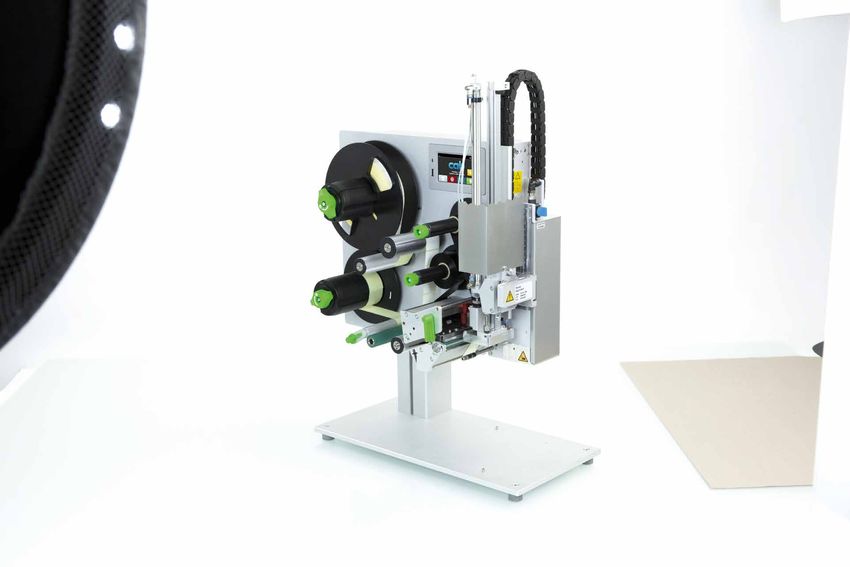
2

      cabPROTECT

Data security in label printing
Modern manufacture sees marking systems work autonomous, interact among each other, with host computers
or a plant control unit. Data security is a key issue. The integration of components, their administration
and authentification are sensitive tasks demanded from the corporate IT. cab systems developed for printing
and applying labels1 provide proper features by default, fairly protecting your data in a network.

               Permissions can be assigned to users                      Firmware updates are verified for integrity
               and restricted by passwords.                              before installation.

               Access to network services (HTTP, FTP,                    Network protocols can be encrypted using
               VNC, OPC UA etc.) is possible only for users              TLS/SSL. To connect securely in a network,
               with authorization. Network services                      a certificate as required is installed
               can be switched on or off.                                in the device ex factory.

               Wireless interfaces (WLAN, Bluetooth)                     USB slots can be locked and access
               can be switched on or off. WPA2 and WPA2                  to external storage media be denied.
               Enterprise levels of security are supported.

All the current cab printing systems are based on the same electronics and firmware.
The printer language is the same, so are interfaces and memory. Any further developed operating system
or driver is available immediately on every device. Resets to default settings are PIN-protected.

1
    models SQUIX, MACH 4S, EOS 2/5, AXON 1/2, HERMES Q, PX Q, IXOR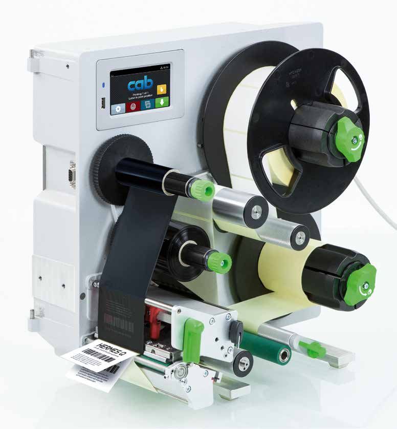
3

Contents

Page 2 . . . . . . . . . . . . . . . . . . . . . . . . . . . . . . . . . . . . . . . . .  cabPROTECT

Pages 4 - 13 . . . . . . . . . . . . . . . . . . . . . . . . . . . . . . . . . . . .  HERMES Q

Pages 14 - 15 . . . . . . . . . . . . . . . . . . . . . . . . . . . . . . . . . . .  Software

Pages 16 - 33 . . . . . . . . . . . . . . . . . . . . . . . . . . . . . . . . . . .  Applicators

Page 34 . . . . . . . . . . . . . . . . . . . . . . . . . . . . . . . . . . . . . . .  Tools to assemble

Pages 35 - 36. . . . . . . . . . . . . . . . . . . . . . . . . . . . . . . . . . .  Floor stands

Pages 38 - 42 . . . . . . . . . . . . . . . . . . . . . . . . . . . . . . . . . .  Delivery program

Page 43 . . . . . . . . . . . . . . . . . . . . . . . . . . . . . . . . . . . . . . . . cab product overview
4
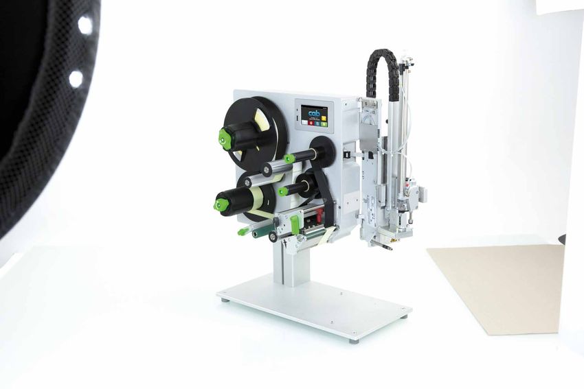
HERMES Q
Printing labels and applying them automatically in production lines
1.1
The slim one
to print small labels
Label printer HERMES Q2
Printable resolution dpi 300 600
Print speed up to mm/s 300 150
Print width up to mm 56.9 54.1
Label roll outside diameters mm 205 / 305
Label width up to mm 58
1.2
The universal one
An industrial bestseller, providing a wide range of accessories
Label printer HERMES Q4.3 HERMES Q4
Printable resolution dpi 200 300 300 600
Print speed up to mm/s 300 300 300 150
Print width up to mm 104 108.4 105.7 105.7
Label roll outside diameters mm 205 / 305
Label width up to mm 114
1.3
The wide one
to print Odette, UCC and GS1 labels in logistics applications
Label printer HERMES Q6.3
Printable resolution dpi 200 300
Print speed up to mm/s 250 250
Print width up to mm 168 162.6
Label roll outside diameters mm 205 / 305
Label width up to mm 174
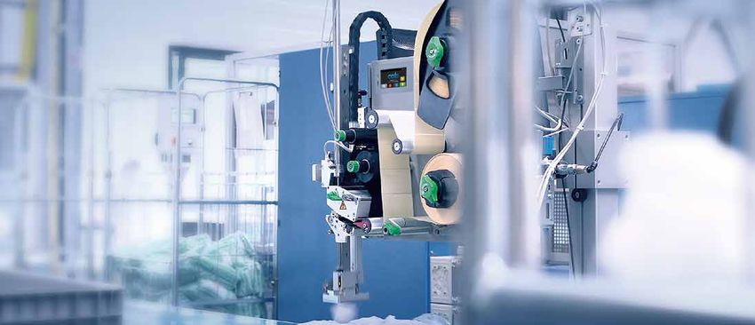
Sample applications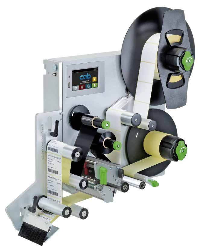
5

Label rolls
All units can provide an unwinder for
picking up rolls with maximum diameter
either 205 mm or 305 mm.

Directions to which
dispense labels
All units can be designed for providing
labels either to the left or to the right.

                                                         left                 right

Orientations of assembly
All the units can be rotated vertically by at most 360°
or assembled in horizontal orientation.

                       0°                          90°          180°   270°   horizontal
6

HERMES Q in detail

                                                                                                                                              9

1

2

3

                                                                                                                                              10

4

5

6
                                                                                                                                              11
7
                                                                                                                                              12
8

❶	Operation panel                                                      ❽	Peel-off plate
  Self-explanatory symbols are on display. The device can thus             Pivoting improves labels be applied to packages.
  be operated intuitively and settings be configured easily.
                                                                        ❾	Label unwinder
❷	Ribbon holder                                                          A swing arm and an integral brake enable labels
  On the basis of three-part tightening axles,                            be unwound at constant force.
  ribbons can be replaced easily and quickly.
                                                                        ❿	Liner rewinder
❸	Rugged metal chassis                                                    Subsequent to all the labels been dispensed, the entire liner
   It is made of cast aluminum. All the parts are assembled to it.         tape is rewound. On the basis of a three-part tightening axle,
                                                                           a liner tape can be inserted and removed easily.
❹	Applicator
   It is assembled to hinge pins. It can be pivoted in case of          ⓫	Pulling system
   maintenance or if materials have to be replaced.                        A liner tape is clamped between a draw roller and a pinch roller.
                                                                           Labels are dispensed using feed synchronous to the print roller.
❺	Pressing plungers
   One is fixed near the chassis wall. The second one is pushed to      ⓬	Label sensor
   the label margin, as far as necessary to evoke a good print image.      Imprint is precisely set on spot on a label and materials ending
                                                                           detected by a transmissive or a reflective sensor.
❻	Print head
   Units of the same width are interchangeable.                           Accurate imprint
   Replacement requires only few steps.                                 	The smaller a label, the higher are the demands regarding the
                                                                          accuracy of an imprint. Print offset can be reduced by ±0.2 mm
❼	Print roller
                                                                          using adjustable slip correction.
   It can be removed/inserted quickly in cases of cleaning or wear.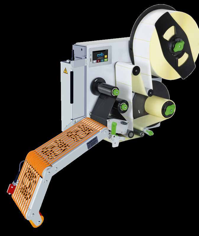
7

Print heads
                    Units of the same width are interchangeable.
                    They are detected by the CPU automatically and calibrated.
                    The print distance to the locating edge can be adjusted.
                    Major data such as the operational performance,
                    maximum operating temperature and heat energy
                    are recorded on the print head. Data can be read at the factory.
                    Print heads provided for HERMES Q2, HERMES Q4 - 300, 600 dpi
                    - sharp-edge print images
                    - e.g. when printing small fonts and graphics on typeplates
                    - e.g. when printing on materials requires high energy needs
                    Print heads provided for HERMES Q4.3, HERMES Q6.3 - 200, 300 dpi
                    persistent; when labeling in rough settings and thermal direct method

Print rollers       Two types of materials:

2.10                Print rollers DR
                    providing a synthetic rubber coating
                    They enable highly accurate imprint and are provided by default.
                    Print rollers DRS
                    providing a silicone coating
                    Product life is extra long, taken a higher print offset into account.

Interfaces
                    ❶	to insert a SD memory card
                    ❷	2 USB hosts to connect a service key, USB memory stick, keyboard,
                       barcode scanner, USB Bluetooth adapter, USB WLAN stick,
                       warning light, an external operation panel
                    ❸	USB 2.0 Hi-Speed to connect a PC
                1

                2
                    ❹	Ethernet 10/100 Mbit/s
                3
                    ❺	RS232C 1,200 to 230,400 baud /8 bits
                4
                    ❻	Digital I/O interface; socket connector SUB-D, 25 pins
                5      compliant with IEC/EN 61131-2, types 1+3;
                       All the inputs and outputs are isolated galvanically and protect
                6      from reverse polarity. In addition, outputs are short-circuit proof
                    	PNP inputs                         PNP, NPN outputs
                      Start printing or labeling         Device ready
                7
                      Print first label                  Print data available
                      Reprint                            Initial / upper end position
                      Delete print job                   Paper feed ON
                      Label removed                      Label in transfer position
                      Stop printing or labeling          Label application / lower end
                      Label feed                         position
                      Label rotated by 90°               Pre-warning to a ribbon ending
                      (to be applied by applicator 4214) Pre-warning to a label web ending
                      Pause                              End of a ribbon and/or a label web
                      Reset                              Collective error

                    Option:
                    ❼	2 port Ethernet switch 10/100 Mbit/s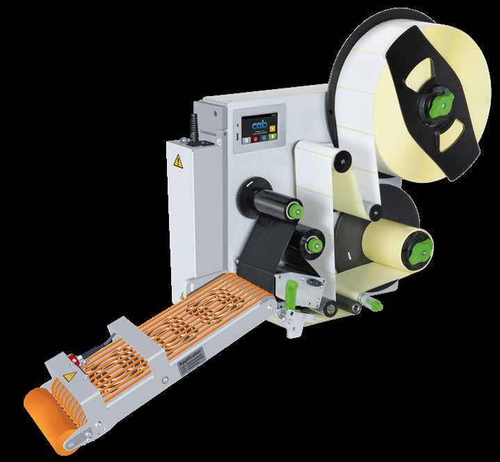
8

Operation panel
Self-explanatory symbols are on display. The device can thus                    Landscape or portrait display,
be operated intuitively and settings be configured easily.                      depending from the orientation of assembly
❶	LED: Power ON
                                                                            2
❷	Status bar: data reception, record data stream, pre-warning
   to a ribbon ending, SD memory card / USB memory stick plugged in,
   Bluetooth, WLAN, Ethernet, USB slave, time                               1

❸	Printer status: ready, pause, number of labels printed in a print job,   3
   label in transfer position, awaiting external start signal               4

❹	USB slot to connect a service key or a memory stick,
   to transfer data to the IFFS memory                                      5

❺	Operation
                                                                                Printer rotated by 90°
         Printing and applying labels in individual steps
         Jump to menu
         Reprint the latest label
         Interrupt and continue a print job

         Stop and delete all print jobs
         Label feed

Setup options                       Print parameters

Print offset Y                      Print speeds                                Video tutorials

External operation panel
Functionalities are the same as on a printer                                                 1

Landscape or portrait display
Operators are free to choose whether to instruct
on an external panel or the one on the printer.
                                                                                     3
USB 2.0 Hi-Speed to connect to a printer

❶ LED: Power ON
❷	USB slot to connect a service key or a memory stick,
   to transfer data to the IFFS memory
❸ C
   onnecting USB cable, lengths of 1.8 to 16 m are provided                                 2
  If length exceeds 3 m, use specified cables only.
  For dimensions see assembly instructions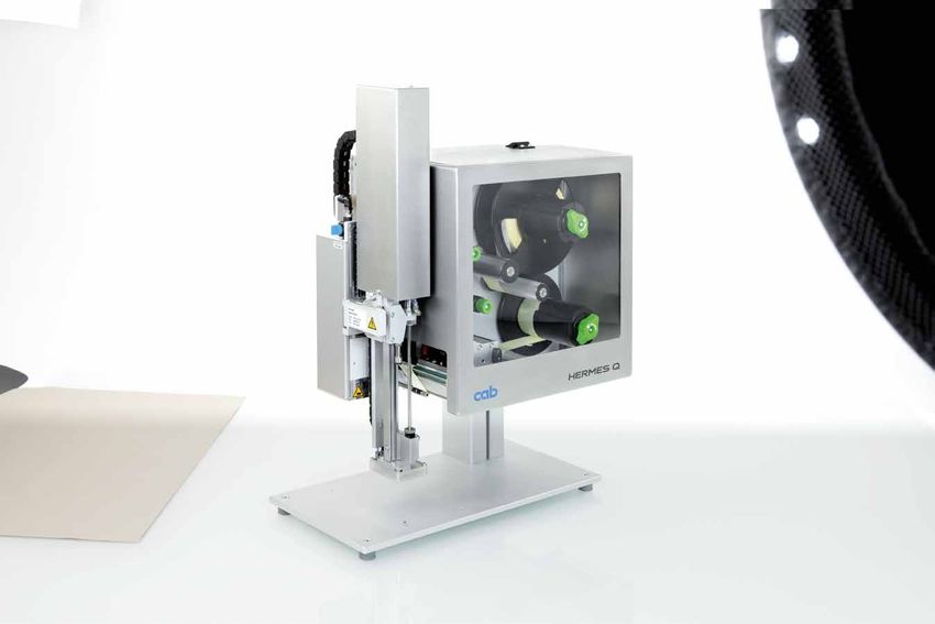
9
Accessories
Accessorial products are plugged or screwed to a printer by the customer.
1.1 1.2 1.3
Pos. Designation roll Ø 205 305 HERMES Q2 HERMES Q4.3 HERMES Q4 HERMES Q6.3
2.1 SD memory card
2.2 USB memory stick
2.3 USB WLAN stick
2.4 USB WLAN stick including a rod antenna
2.5 USB Bluetooth adapter
2.6 Product sensor, 3 pins -
2.7 Product sensor, 25 pins
2.8 I/O interface connector SUB-D, 25 pins
2.9 Warning light
External operation panel
2.10
Connecting USB cable
2.11 Label selection - I/O box
2.12 Hand switch TR2
2.13 Foot switch
2.14 Connecting RS232 C cable
2.15 Scanner CC200
2.1 2.10
SD memory card External operation panel
If the operation panel on a printer
2.2
USB memory stick cannot be accessed after the device
has been installed, an external
2.3 USB WLAN stick one can be attached in addition.
2.4 GHz 802.11b/g/n
hotspot or infrastructure mode
Printer connection: USB 2.0 Hi-speed
2.4 USB WLAN stick including a rod antenna device
to extend the range of operation
2.4 GHz 802.11b/g/n + 5 GHz 802.11a/n/ac Connecting cables are required for power
hotspot or infrastructure mode supply. The following or equivalent
cables ensure functionality.
2.5 USB Bluetooth adapter
2.6 Product sensor, 3 pins Connecting USB cable, 1.8 m
to be attached to a front side applicator, Connecting USB cable, 3 m
a vacuum belt applicator or an air jet box. Connecting USB cable, 5 m
Labels are triggered to be applied Connecting USB cable, 11 m
as soon as a product has been detached, Connecting USB cable, 16 m
e.g. on a conveyor belt. 2.11
2.7 Product sensor, 25 pins Label selection - I/O box
Labels are triggered to be applied A maximum of 16 different labels
as soon as a product has been detached, can be selected from a memory card
e.g. on a conveyor belt. by a master control unit, e.g. PLC.
2.8 I/O interface connector SUB-D, 25 pins 2.12
All control signals can be attached to Hand switch TR2
the I/O interface using clamping screws. to be attached to the I/O interface
2.13
Foot switch
2.9 Warning light
to be attached to the I/O interface
In addition to the information
indicated on the display of a printer, 2.14
states are signalled. Connecting RS232 C cable
9/9 pins, 3 m
Red Collective error
Yellow Pre-warning to a label web 2.15
Scanner CC200
or a ribbon ending
provided on request
Green Device ready
1 A connecting cable and materials
to assemble to a chassis or a bracket
are included on delivery.
USB connection to HERMES Q,
connecting cable 1 m
1 Chassis assembly
2 2 Bracket assembly
10
Options They
are parts or units to perform special functions.
are assembled to a printer in addition to
If order implies options be assembled ex factory,
the part numbers of such printers and options are added by .250.
or instead of standards. Options delivered separately are added by .001.
Pos. Designation roll Ø 205 305 HERMES Q2 HERMES Q4.3 HERMES Q4 HERMES Q6.3 .250 .001
3.1 Automatic ribbon saving - -
3.2 Label unwinder K40
3.3/3.4 Adapters 40/50 and 76/100
3.5 Spacers - -
3.6 Margin stop 10 -
3.7 Cover -
3.8 Print head pressure system, reduced force -
3.9 Extended peel-off plate (+10 mm)
3.10 Print roller DRS
3.11 Antistatic brush -
3.12 Draw roller ZS
3.13 2 port Ethernet switch 10/100 Mbit/s
3.1 Automatic ribbon saving
Use is recommended in cases of at least 60 mm unprinted area
on a label. While labels are fed, the print head is lifted and the
assembly
ribbon stopped, resulting in less material consumption.
ex factory only
3.2 Label unwinder K40
to process label rolls having a core diameter of 40 mm
Adapter 40/50
3.3
to pick up label rolls having a core diameter of 50 mm
and minimum widths of 20 mm. One adapter is sufficient
if material width does not exceed 50 mm.
Operate only with a label unwinder K40.
Adapter 76/100
3.4
to pick up label rolls having a core diameter of 100 mm
and minimum widths of 20 mm. One adapter is sufficient
if material width does not exceed 50 mm.
Spacers
3.5
to process narrow labels provided on liners ≤ 20 mm wide, wound
on a roll or a reel. Ribbon protruding on both sides prevents from
wrinkling. The label guidance is therefore offset by 7 mm from the
middle wall with spacers.
Reel plate wall thickness 1 - 2 mm
3.6 Margin stop 10
to guide narrow labels provided on a liner 10 - 24 mm wide,
wound on a roll (no reels) having a core diameter of 76 mm.
Operate only with a spacer11
Options
3.7 Cover
to prevent from contamination and contact
Maximum outside diameter for label rolls is 205 mm
If the tamp-on pad of an applicator immerses more than 25 mm,
the cover must be adapted.
Assembly in vertical orientation, rotated by ± 90° or horizontally
3.8 Print head pressure system, reduced force
Thermal direct printing requires less pressure on a print head.
Reduced force results in a decrease of wear. Product life extends.
Thermal direct printing only
3.9 Extended peel-off plate (+10 mm)
Recommended
- if labels are picked up by a robotic arm,
- if readable area is required for scanning,
- when installing an antistatic brush
3.10 Print roller DRS
Silicone coating enables an extra long product life,
taken a higher print offset into account
3.11 Antistatic brush
Electrostatic charge is reduced when plastic labels
are printed and peeled off.
Operate only with an extended peel-off plate.
3.12 Draw roller ZS
Made of steel, to avoid tension on a liner tape:
- if label height exceeds 150 mm
- when peeling off without backfeed
- if thick liner materials are processed
- when applying labels using a demand module 5114/16
3.13 2 port Ethernet switch 10/100 Mbit/s
to connect another terminal device in a joint network.
Signals are looped through.12
Technical data typical standard option
Label printer type HERMES Q2 HERMES Q4.3 HERMES Q4 HERMES Q6.3
Thermal transfer
Printing method
Thermal direct – – – –
Printable resolution dpi 300 600 200 300 300 600 200 300
Print speed up to mm/s 300 150 300 300 300 150 250 250
Print width bis mm 56.9 54.1 104 108.4 105.7 105.7 168 162.6
Direction to which dispense labels L = to the left, R = to the right
Print distance to the locating edge mm 1 1 1 1 1 1 1 1
incl. automatic ribbon saving L/R mm – – 2.2/1.6 0/-0.7 1/1 1/1 0.2/0.2 2.9/2.9
Materials
Labels paper, PET, PE, PP, PI, PVC, PU, acrylate, Tyvec
on a roll
on a reel – – –
Labels1) Width mm 4 - 58 10 - 114 10 - 114 46 - 174
Height from mm 3 4 4 6
Thickness up to mm 0.60 0.60 0.60 0.60
Liner tape Width if operating a roll mm 24 - 62 24 - 118 24 - 118 50 - 178
Width2) if operating a reel or a roll mm 10 - 24 – 10 - 24 –
Thickness up to mm 0.16 0.16 0.16 0.16
Roll unwinder Outside roll diameter up to mm 205 / 305 205 / 305 205 / 305 205 / 305
reel diameter up to mm 205 – – –
Core diameter mm 76
Winding outside or inside
Roll rewinder Outside diameter up to mm 155 / 205
Core diameter mm 76
Ribbon3) Ink side outside or inside
Roll diameter up to mm 90
Core diameter mm 25.4
Length up to m 600
Width mm 25 - 67 25 - 114 25 - 114 50 - 170
Automatic ribbon saving –
Printer dimensions and weights
Widthmm 207 260 260 320
Height roll diameters 205 / 305 mm 400 / 430
Depth roll diameters 205 / 305 mm 400 / 500
Weight roll diameters 205 / 305 approx. kg 15 / 16 16 / 17 16 / 17 20
Label sensor indicating positions
Transmissive sensor detecting labels, punch marks or print marks, as well as materials ending
Reflective sensor bottom reflex detecting print marks on non-transparent liners, as well as materials ending
Sensor distance to the locating edge mm 2 - 26 2 - 60 2 - 60 2 - 60
Material passage mm 2
Electronics
32-bit processor MHz 800
RAM MB 256
IFFS memory MB 50
Slot to insert a memory card (SDHC, SDXC)
Battery to display date and real time
Data (e.g. serial numbering) preserved if power turns off
Interfaces
RS232C 1,200 to 230,400 baud / 8 bits
USB 2.0 Hi-Speed to connect a PC
LPD, RawIP printing, SOAP Webservice, OPC UA, WebDAV
Ethernet 10/100 Mbit/s
DHCP, HTTP/HTTPS, FTP/FTPS, TIME, NTP, Zeroconf, SNMP, SMTP, VNC
1 USB host on the operation panel provided for a service key, USB memory stick, USB WLAN stick, USB Bluetooth adapter
a keyboard, barcode scanner, USB memory stick, warning light, USB WLAN stick,
2 USB hosts on the back of the device provided for
USB WLAN stick including a rod antenna, USB Bluetooth adapter, an external operation panel
USB host 24 VDC, to connect a peripheral device
Digital I/O interface, 10 inputs / 11 outputs
2 port Ethernet switch 10/100 Mbit/s
1)
Limitations can occur when processing small labels, thin materials or materials using a strong adhesive. Critical applications need testing.
2)
Spacers attached to the label unwinder and the unit rewinding the liner tape help feeding the ribbon centered above the labels.
3)
The ribbon must correspond at least to the width of the liner tape.13 Technical data standard option Operating data Fonts Voltage 100-240 VAC, 50/60 Hz, PFC Bitmap fonts Widths and heights 1 - 3 mm Power consumption standby
14

cablabel S3 software
Design, print, administrate
cablabel S3 opens up the full potential of cab devices.
Creating a label is the first step. cablabel S3 adapts to
requirements easily using a modular design. Plug-ins like the
JScript Viewer support native JScript programming, as well as
other features. The designer user interface and the JScript code
synchronize in real time. The Database Connector and other
special features can be integrated, so are barcode verifiers.

              For further information see
              www.cab.de/en/cablabel

Stand-alone printing
A printer can select and print labels even when the system
is disconnected from a host.
Labels are designed using software such as cablabel S3
or a text editor on a PC. Label formats, texts, graphics and data
taken from a database are transferred to a memory card,
a USB memory stick or the internal IFFS memory.
Only variable data are sent to the printer using a keyboard,
a barcode scanner, scale or another host system and/or are
recalled from a host by the Database Connector and printed.

OPC UA
The latest cab printers are ready to interact with machines
and components of different manufacturers in industrial plants.
An OPC UA server and a client are part of the firmware.
The server enables a printer be configured and controlled. Dynamic
print data can be edited using a defined programming interface.
The integral client enables reading data fields from other machines
ready for OPC UA, as well as transferring data to a label.
No additional software is needed.
15
Printer control Printer administration
Drivers Configuration on the Intranet / Internet
cab provides 32 / 64-bit drivers to control a printer with software cab printers integrate a HTTP and FTP server. A printer
other than cablabel S3. Running the drivers requires at least can be controlled and configured, firmware updated
operating systems Windows Vista, Mac OS 10.6, Linux CUPS 1.2. and memory cards managed using a standard web browser
or FTP client. Administrators and operators are notified of states,
Windows1) drivers warnings and errors via email or datagrams, based on a SNMP/
compliant to WHQL standards SMTP client. Time and date are synchronized by a time server.
Mac OS X 2)3) drivers
based on CUPS
Linux3) drivers
based on CUPS
Free download on www.cab.de/en/support
Programming Network Manager in preparation
JScript Several printers of a network can be controlled
and configured simultaneously, firmware updated,
To control a printer, cab developed the embedded JScript
memory cards managed, data synchronized
programming language. Free manual download on
www.cab.de/en/programming and PINs administrated from one place.
abc Basic Compiler
An integral part of the firmware, it adds to JScript in terms
of programming a printer before data are edited for processing.
For example, external printer languages can be replaced without
intervening in the print job in process. Data may be transferred
also from other systems, such as scales, barcode scanners or PLC.
Integration Database Connector
Printer Vendor Program Printers connected to a network are enabled to access
data directly from a central ODBC / OLEDB database
As a member in this program, cab developed a replace
method by which cab printers can be controlled from SAP4)R/3 and transfer it to a label. While labels are printed, data can be
using SAPScript. Only variable data are sent by a host system rewritten to the database.
to the printer. Data such as pictures and fonts which had been
transferred to a local memory (IFFS, memory card, etc.) before,
are collected.
Step 1 Step 2 Step 3
Create a label Take the replace Printout from SAP
and a replace file file and replace
using cablabel S3 variable data
using SAPScript
1)
Windows is a registered trademark of the Microsoft Corporation
2)
MAC OS X is a registered trademark of Apple Computer, Inc.
3)
models SQUIX, MACH 4S, EOS, HERMES Q, PX Q only
4)
SAP and all its corresponding logos are trademarks or registered trademarks of SAP SE16
Applicators
HERMES Q has been designed for printing
and applying labels automatically in
production lines. Labels are applied by
applicators, using transfer modules to roll,
blow or tamp labels on products or packages.
❶ Long product life
The precise and low-wear linear guide
is using a ball bearing chain.
❷ P
roducts of variable heights
Labels can be applied on different heights
using a stroke cylinder. Its standard lengths
are 200, 300 and 400 mm. Further lengths
can be provided on request.
❸ Protective chassis
is a standard to protect the cylinder
and the guide. It can be provided adapted
to the product jig on a labeling workstation.
❹ H
ighly reliable processes
Support air and intake air can be defined,
so can stroke speed. Sensor control
❺ Label application
in real time. Small or large labels,
4 to 250 mm high and 4 to 174 mm wide,
can be processed using an applicator.
Pressure-reducing valve
It reduces the pressure exerted by
the stroke cylinder to a product.
❻ Pivoting applicator
The print mechanics can be accessed
quickly and easily in case of maintenance
or if materials have to be replaced.17
Applicators and transfer modules
r
ye
a
p
la
g
o
in
t
ng
ls
us
- m te d
pi
ed
be
di am
nt
d
la
ng un
re
ad
ou
a
o
ng
m
er
, p ing
g-
sf
in
id
vi
an
ri
Ro o n p s p r
v
ro
d
ro
p
be le
tr
a n p pa
s
,p
um du
d,
on d,
ad
e
d
ad
ad
r m pa d
pa
lt
o
pa
a
ar
d
ra
lp
p
Va d m
pa
p
l
Un ad
e
-w
on
on
sa
a
on
ls
n
at
s
-o
p
er
er
er
be
p-
p-
p-
pl
p-
ow
rn
cu
ll -
iv
iv
m
m
m
m
m
m
La
Un
Overview
De
Co
Fo
Ta
Ta
Ta
Te
Ta
Bl
HERMES Q
2 4 6.3
Applicators Order code Page 11 11 12 61 21 88 31 31 41 51 — — 90
Swing applicator 3214 3214 18 — F F F — — — — — — — —
4114 4114 19/20 — F F F — — — — — — —
Stroke applicator
Product marking
4116 19/20 — F F F — — — — — — — —
Stroke turn applicator 4214 4214 21 — F F F — — — — — — — —
Stroke applicator 4414 4414 22 — F F F — — — — — — — — —
Swing stroke applicator 4514 4514 23 — — — — — — — — — — — —
Flag applicator 4712 24 — — — — — — — — — — — —
3014 25 — — — — — — — — — —
Front side applicator
3016 25 — — — — — — — — — — —
4014 26/27 F — — — — — —
Stroke applicator
Package marking
4016 26/27 — — — — — — — — — —
Stroke blow applicator 4614 28 — — — — — — — — — — — —
Demand module 5114 5116 29 — — — — — — — — — — — —
5314 5316 30
Vacuum belt applicator — — — — — — — — — — — —
5414 5416 31
Air jet box 6114 32 — — — — — — — — — — — —
Applicator type code 4414L-200 F Tamp-on pad immersing in the surface along a label
For depths of immersion see the
441
Type specified technical data of an applicator.
Label printer HERMES Q2 2 If an applicator immerses more than 25 mm,
HERMES Q4 4 the cover of HERMES Q must be adapted.
HERMES Q4.3 4
HERMES Q6.3 6
Direction to which left L
dispense labels right R
Cylinder stroke 200
300
400
500
600
on request
700
80018
Product marking
Swing applicator 3214 4.1
Labels very small or midsized can be applied in real time,
preferably from the side.
The pad locates in front of the peel-off plate. It picks up a label
while it is being printed. A rotary cylinder pivots into position.
The label is transferred to a product by a stroke cylinder.
Rotary angles and linear hubs are adjustable.
Accessories
5.13 Blow tube
5.14 Unit to regulate compressed air
Tamp-on pad Tamp-on pad, providing a damping layer Blow-on pad
Labels are precisely tamped on plane surfaces. When applying labels to hard surfaces, the It benefits when labels have to be applied
Recessed levels are possible as well. noise level is reduced. It benefits also in cases to sensitive surfaces or products in motion.
of rough structures or little unevenness. Labels are blown on by a blast of air.
Stroke cylinder adjustment enables
Tamp-on pad, providing a label stop bridging distances of 5 to 10 mm
It enables small labels be applied to the surface of a product.
exactly on spot to a product.
Tamp-on pad, Tamp-on pad,
Tamp-on pad Blow-on pad
providing a damping layer providing a label stop
Technical data 3214 L/R 11 F 3214 L/R 12 F 3214 L/R 61 F 3214 L/R 2100
Label widths operating a HERMES Q2 mm 4 - 58 10 - 58 10 - 58 10 - 58
HERMES Q4/Q4.3 mm 10 - 114 10 -114 10 -114 10 - 80
Label heights operating a HERMES Q2 mm 5 - 80 8 - 80 5 - 80 10 - 80
HERMES Q4/Q4.3 mm 8 - 80 8 - 80 8 - 80 10 - 80
State of a product at rest
at the moment a label is applied in motion - - -
Label application from the side
Product heights uniform
Distance of a product to the peel-off plate mm 250 - 280
Linear guidance, horizontal mm 5 - 30
Pivot angles 45° - 95°
Depth of a pad immersing F up to mm 30 30 30 -
Compressed air bar 4.5
Cycle rate1) labels/min approx. 20
1)
calculated using labels 40 mm high and a print speed of 100 mm/s19
Product marking
Stroke applicators 4114, 4116 4.2
Labels very small or midsized can be applied in real time from all sides.
The pad locates in front of the peel-off plate. It picks up a label
while it is being printed. Powered by a short stroke cylinder,
the pad is brought into position in horizontal direction.
The label is transferred to a product by a stroke cylinder.
The length of the stroke cylinder defines the maximum distance
of a product to the peel-off plate.
Accessories
5.13 Blow tube
5.14 Unit to regulate compressed air
5.17 Pressure-reducing valve
Tamp-on pad Tamp-on pad, providing a damping layer Blow-on pad
Labels are precisely tamped on plane surfaces. When applying labels to hard surfaces, the It benefits when labels have to be applied
Recessed levels are possible as well. noise level is reduced. It benefits also in cases to sensitive surfaces or products in motion.
of rough structures or little unevenness. Labels are blown on by a blast of air.
Stroke cylinder adjustment enables
Tamp-on pad, providing a label stop bridging distances of 5 to 10 mm
It enables small labels be applied to the surface of a product.
exactly on spot to a product.
Tamp-on pad, Tamp-on pad,
Tamp-on pad Blow-on pad
providing a damping layer providing a label stop
Technical data 4114, 4116 L/R 11 F 4114, 4116 L/R 12 F 4114, 4116 L/R 61 F 4114 L/R 2100
Label widths operating a HERMES Q2 mm 4 - 58 10 - 58 10 - 58 10 - 58
HERMES Q4/Q4.3 mm 10 -114 10 -114 10 -114 10 -114
HERMES Q6.3 mm 50 -174 50 -174 50 -174 -
Label heights operating a HERMES Q2 mm 4 - 80 8 - 80 4 - 80 10 - 80
HERMES Q4/Q4.3 mm 8 - 80 8 - 80 8 - 80 10 - 80
HERMES Q6.3 mm 8 - 80 8 - 80 8 - 80 -
State of a product at rest
at the moment a label is applied in motion - - -
Label applications from the top
from below
from the side
Product heights uniform - - -
variable -
Short stroke cylinder, horizontal mm 10
Distance of a product to the bottom of the unit
using a cylinder stroke of 200 up to mm 135 135 135 140
300 up to mm 235 235 235 240
400 up to mm 335 335 335 340
Depth of a pad immersing F1) up to mm 110 110 110 -
Compressed air bar 4.5
Cycle rate2) labels/min approx. 30
1)
If an applicator immerses more than 25 mm, the cover of HERMES Q must be adapted.
2)
calculated using a stroke of 100 mm below the unit, labels 40 mm high, a print speed of 100 mm/s20
Product marking
Stroke applicators 4114, 4116 4.2
Labels very small or midsized can be applied in real time from all sides.
The pad locates in front of the peel-off plate. It picks up a label
while it is being printed. Powered by a short stroke cylinder,
the pad is brought into position in horizontal direction.
The label is transferred to a product by a stroke cylinder.
The length of the stroke cylinder defines the maximum distance
of a product to the peel-off plate.
Accessories
5.13 Blow tube
5.14 Unit to regulate compressed air
5.17 Pressure-reducing valve
Form pad
Labels are precisely applied to cylindric objects,
inclined or curved surfaces. Curved form pads prevent
from blistering on very smooth and plane surfaces.
200° maximum label wrapping on cylindric objects
Form pad
Technical data 4114, 4116 L/R 8800
Label widths operating a HERMES Q2 mm 10 - 58
HERMES Q4/Q4.3 mm 10 - 114
HERMES Q6.3 mm 50 - 174
Label heights mm 8 - 80
State of a product at rest
at the moment a label is applied
Label applications from the top
from below
from the side
Product heights variable
Short stroke cylinder, horizontal mm 10
Distance of a product to the bottom of the unit
using a cylinder stroke 200 up to mm 135
300 up to mm 235
400 up to mm 335
Compressed air bar 4.5
Cycle rate1) labels/min approx. 20
1)
calculated using a stroke of 100 mm below the unit, labels 40 mm high, a print speed of 100 mm/s
If the height of the form pad exceeds 25 mm, the cover of HERMES Q must be adapted.21
Product marking
Stroke turn applicator 4214 4.3
Labels very small or midsized can be applied in real time
from all sides whenever the unit is difficult to install.
The pad locates in front of the peel-off plate. It picks up a label
while it is being printed. Powered by a rotary cylinder, the pad pivots
into position by at most 180° in horizontal direction. The label is trans-
ferred to a product by a stroke cylinder. The length of the stroke cylinder
defines the maximum distance of a product to the peel-off plate.
Accessories
5.13 Blow tube
5.14 Unit to regulate compressed air
5.17 Pressure-reducing valve
Tamp-on pad Tamp-on pad, providing a damping layer Blow-on pad
Labels are precisely tamped on plane surfaces. When applying labels to hard surfaces, the It benefits when labels have to be applied
Recessed levels are possible as well. noise level is reduced. It benefits also in cases to sensitive surfaces or products in motion.
of rough structures or little unevenness. Labels are blown on by a blast of air.
Stroke cylinder adjustment enables
Tamp-on pad, providing a label stop bridging distances of 5 to 10 mm
It enables small labels be applied to the surface of a product.
exactly on spot to a product.
Tamp-on pad, Tamp-on pad,
Tamp-on pad Blow-on pad
providing a damping layer providing a label stop
Technical data 4214 L/R 11 F 4214 L/R 12 F 4214 L/R 61 F 4214 L/R 2100
Label widths operating a HERMES Q2 mm 4 - 58 10 - 58 10 - 58 10 - 58
HERMES Q4/Q4.3mm 10 - 80
Label heights operating a HERMES Q2 mm 4 - 40 8 - 40 4 - 40 10 - 40
HERMES Q4/Q4.3mm 8 - 40 8 - 40 8 - 40 10 - 40
State of a product at rest
at the moment a label is applied in motion - - -
Label applications from the top
from below
from the side
Product heights uniform - - -
variable -
Rotary angle, horizontal 90°, 0°
180° if labels are no more than 15 mm high
Distance of a product to the bottom of the unit
using a cylinder stroke of 200 up to mm 135 135 135 140
300 up to mm 235 235 235 240
400 up to mm 335 335 335 340
Depth of a pad immersing F1) up to mm 65 65 65 -
Compressed air bar 4.5
Cycle rate2) labels/min approx. 20
1)
If an applicator immerses more than 25 mm, the cover of HERMES Q must be adapted.
2)
calculated using a stroke of 100 mm below the unit, labels 40 mm high, a print speed of 100 mm/s22
Product marking
Stroke applicator 4414 4.4
Labels very small or midsized can be applied in real time from all sides.
Positions to which labels shall be applied can be adjusted
in directions x and y.
The pad locates in front of the peel-off plate. It picks up a label
while it is being printed. Powered by two short stroke cylinders,
the pad is brought into position. The label is transferred to a product
by a stroke cylinder. The length of the stroke cylinder defines
the maximum distance of a product to the peel-off plate.
Accessories
5.13 Blow tube
5.14 Unit to regulate compressed air
5.17 Pressure-reducing valve
Tamp-on pad Tamp-on pad, providing a damping layer
Labels are precisely tamped on plane surfaces. When applying labels to hard surfaces, the noise level is reduced.
Recessed levels are possible as well. It benefits also in cases of rough structures or little unevenness.
Tamp-on pad, providing a label stop
It enables small labels be applied exactly on spot to a product.
Tamp-on pad, Tamp-on pad,
Tamp-on pad
providing a damping layer providing a label stop
Technical data 4414 L/R 11 F 4414 L/R 12 F 4414 L/R 61 F
Label widths operating a HERMES Q2 mm 4 - 58 10 - 58 10 - 58
HERMES Q4/Q4.3mm 10 -114
Label heights operating a HERMES Q2 mm 4 - 80 8 - 80 4 - 80
HERMES Q4/Q4.3mm 8 - 80
State of a product at rest
at the moment a label is applied
Label applications from the top
from below
from the side
Product heights variable
Short stroke cylinders, horizontal direction x mm 3-7
direction y mm 11 - 15
Distance of a product to the bottom of the unit
using a cylinder stroke of 200 up to mm 135
300 up to mm 235
400 up to mm 335
Depth of a pad immersing F1) up to mm 90
Compressed air bar 4.5
Cycle rate2) labels/min approx. 25
1)
If an applicator immerses more than 25 mm, the cover of HERMES Q must be adapted.
2)
calculated using a stroke of 100 mm below the unit, labels 40 mm high, a print speed of 100 mm/s23
Product marking
Swing stroke applicator 4514 4.5
Labels can be applied in real time from all sides on inner surfaces
of profiles and pipes. Stroke cylinder adjustment enables labels
be transferred exactly to their dedicated spots.
The pad locates in front of the peel-off plate. It picks up a label
while it is being printed. Powered by a rotary cylinder,
the pad pivots to the level on which the label shall be applied.
The label is moved to the point of transfer by a stroke cylinder.
Accessories
5.13 Blow tube
5.14 Unit to regulate compressed air
Blow-on pad
Labels are blown on a product surface by a blast of air,
bridging a distance of 5 to 10 mm.
Blow-on pad
Technical data 4514 L/R 2100
Label widths operating a HERMES Q2 mm 10 - 58
HERMES Q4/Q4.3mm 10 - 80
Label heights mm 10 - 60
State of a product at rest
at the moment a label is applied
Label applications from the top
from below
from the side
Product heights uniform
Pivot angle, vertical 120°
Distance between the bottom of the unit
and the upper label ending
using a cylinder stroke of 200 up to mm 1502)
300 up to mm 2502)
400 up to mm 3502)
Compressed air bar 4.5
Cycle rate1) labels/min approx. 20
1)
calculated using a stroke of 100 mm below the unit, labels 40 mm high, a print speed of 100 mm/s
2)
depending from the height of a label24
Product marking
Flag applicator 4712 4.6
Labels can be applied in real time from all sides precisely
on round materials such as cables, hoses or pipes.
The pad locates in front of the peel-off plate. It picks up a label
while it is being printed. The label is transferred to the spot of
application by a stroke cylinder. A further cylinder guides the material
all around the material using cam control. First, both endings of a label
are stuck together. Then the label is tamped to the round material.
The length of the stroke cylinder defines the maximum distance
of a product to the peel-off plate.
Accessories
5.13 Blow tube
5.14 Unit to regulate compressed air
diameter x π Ø
front side back side Ø
length L of a label flag length L of a label flag
L
L
P
α
P
α
Form pad
Technical data 4712 L 300
Label widths operating a HERMES Q4L/Q4.3L mm 501) - 100
Label heights mm 10 - 50
Diametermm 3 - 16
State of a product at rest
at the moment a label is applied
Label applications from the top
from below
rotated vertically 0 - 180° clockwise (request in case of other rotations)
from the side
Product heights uniform
Distance of a product to the bottom of the unit at least mm 70
using a cylinder stroke of 300 up to mm 260
Depth of pliers immersing mm 55
Offset P up to mm 1.02)
Compressed air bar 4.5
Cycle rate, printing and applying only3) labels/min approx. 15
1)
Processing labels 50 to 58 mm wide requires a spacer.
2)
depending from the quality of a label
3)
calculated using a print speed of 100 mm/s25
Package marking
Front side applicators 3014, 3016 4.7
Labels can be applied in real time from the top or the side to packages
in motion. Front sides or back sides of a package are preferred.
The pad locates in front of the peel-off plate. It picks up a label
while it is being printed. The label is transferred to a product
with the help of a rotary cylinder. The package is detected by a sensor
and the pivot arm with the pad returned to its initial position.
Pivot arm length
°
- 90
s0
le
ng
ta
vo
Pi
Accessories
5.13 Blow tube
5.14 Unit to regulate compressed air
Tamp-on pad Tamp-on pad, spring-mounted Blow-on pad
Labels are precisely tamped on plane surfaces. Labels can be applied to surfaces inclined Labels are blown on a package surface
Recessed levels are possible as well. by a maximum of 15°. Heights within the by a blast of air, bridging a distance
area of a label may vary by 10 mm at most. of 5 to 10 mm.
Tamp-on pad Tamp-on pad, spring-mounted Blow-on pad
Technical data 3014, 3016 L/R 1100 3014, 3016 L/R 3100 3014 L/R 2100
Label widths operating a HERMES Q4/Q4.3 mm 25 - 114 80 - 114 25 - 114
HERMES Q6.3mm 25 - 174 80 - 174 -
Label heights operating a HERMES Q4/Q4.3 mm 8 - 250 80 - 250 10 - 100
HERMES Q6.3 mm 25 - 250 80 - 250 25 - 100
State of a package at rest
at the moment a label is applied in motion
Label applications from the top
from the side
from the front
from the back
Package heights variable
Pivot arm lengths1) mm 200 / 300 / 400
Pivot angles 0 - 90°
Compressed air bar 4.5
Cycle rate2) labels/min approx. 15
1)
Pivot arm length defines the spot of a label (lower margin) to be reached at 90° below a HERMES Q footprint.
2)
calculated using a pivot arm 200 mm long, labels 100 mm high, a print speed of 100 mm/s26
Package marking
Stroke applicators 4014, 4016 4.8
Labels can be applied in real time from all sides to packages.
The type of pad defines whether a package has to be at rest
or can be in motion at the time a label is applied.
The pad locates in front of the peel-off plate. It picks up a label
while it is being printed. The label is transferred to a package with the
help of a stroke cylinder. The package is detected by a sensor and the
pad returned to its initial position. The length of the stroke cylinder
defines the maximum distance of a package to the peel-off plate.
Accessories
5.13 Blow tube
5.14 Unit to regulate compressed air
5.17 Pressure-reducing valve
Tamp-on pad Universal pad Tamp-on pad, spring-mounted Universal pad, spring-mounted
Labels are precisely tamped on Labels can be tamped on plane Labels can be applied to surfaces Labels can be applied to surfaces
plane surfaces. Recessed levels surfaces. Drilled holes are pro- inclined by a maximum of 15°. inclined by a maximum of 15°.
are possible as well. vided in gaps of 5 mm to suck a Heights witin the area of a label Heights in the area of a label
label. The holes are covered by may vary by 10 mm at most. may vary by 10 mm at most.
a sliding foil, but can be opened To suck a label, drilled holes
according to the size of a label are provided in gaps of 5 mm
using a punching tool. and covered by a sliding foil.
Delivery includes two extra foils. Delivery includes two extra foils.
Tamp-on pad, Universal pad,
Tamp-on pad Universal pad
spring-mounted spring-mounted
Technical data 4014, 4016 L/R 11 F 4014 L/R 1100 4014, 4016 L/R 3100 4014 L/R 3100
Label widths operating a HERMES Q4/Q4.3 mm 20 - 114 75 / 90 80 - 114 116 / 116
HERMES Q6.3 mm 50 - 174 - 80 -174 -
Label heights operating a HERMES Q4/Q4.3 mm 20 - 210 60 / 90 80 - 210 102 / 152
HERMES Q6.3 mm 25 - 210 - 80 - 210 -
State of a package at rest
at the moment a label is applied
Label applications from the top
from below
from the side
Package heights variable
Distance of a package to the bottom of the unit
using a cylinder stroke of 200 up to mm 135 135 130 130
300 up to mm 235 235 230 230
400 up to mm 335 335 330 330
Depth of a pad immersing F1) up to mm 120 – – –
Compressed air bar 4.5
Cycle rate2) labels/min approx. 25
1)
If an applicator immerses more than 25 mm, the cover of HERMES Q must be adapted.
2)
calculated using a stroke of 100 mm below the unit, labels 100 mm high, a print speed of 100 mm/s27
Package marking
Stroke applicators 4014, 4016 4.8
Labels can be applied in real time from all sides to packages.
The type of pad defines whether a package has to be at rest
or can be in motion at the time a label is applied.
The pad locates in front of the peel-off plate. It picks up a label
while it is being printed. The label is transferred to a package with the
help of a stroke cylinder. The package is detected by a sensor and the
pad returned to its initial position. The length of the stroke cylinder
defines the maximum distance of a package to the peel-off plate.
Accessories
5.13 Blow tube
5.14 Unit to regulate compressed air
5.17 Pressure-reducing valve
Blow-on pad Roll-on pad Corner-wrap pad
It benefits when labels have to be applied Labels are rolled on plane surfaces Labels are applied to a package on two
to sensitive surfaces or packages in motion. while these packages are in motion. sides adjacent to one another. One half
Labels are blown on by a blast of air. of a label is applied to the top of a package.
Stroke cylinder adjustment enables Then the other half of the label is rolled on.
bridging distances of 5 to 10 mm
to the surface of a package.
130
mm
Blow-on pad Roll-on pad Corner-wrap pad
Technical data 4014 L/R 2100 4014, 4016 L/R 4100 4014 L/R 5100
Label widths operating a HERMES Q4/Q4.3 mm 20 - 114 25 - 114 20 - 114
HERMES Q6.3 mm provided on request 50 - 174 -
Label heights operating a HERMES Q4/Q4.3 mm 20 - 100 80 - 250 60 - 210
HERMES Q6.3 mm provided on request 80 - 250 -
State of a package at rest -
at the moment a label is applied in motion -
Label applications from the top
from below -
from the side -
Package heights uniform - -
variable -
Distance of a package to the bottom of the unit
using a cylinder stroke of 200 up to mm 140 160 100
300 up to mm 240 260 200
400 up to mm 340 360 300
Compressed air bar 4.5
Cycle rate1) labels/min approx. 25 20 20
1)
calculated using a stroke of 100 mm below the unit, labels 100 mm high, a print speed of 100 mm/s28
Package marking
Stroke blow applicator 4614 4.9
Labels can be applied in real time from all sides
on packages of various heights in motion.
The pad locates in front of the peel-off plate. It picks up a label
while it is being printed. Powered by a stroke cylinder and detected
by a sensor, the pad moves to a spot approx. 10 mm above a package.
The length of the stroke cylinder defines the maximum difference
in terms of package heights.
Accessories
5.13 Blow tube
5.14 Unit to regulate compressed air
Blow-on pad
Labels are blown on a package surface by a blast of air,
bridging a distance of 5 to 10 mm.
Blow-on pad
Technical data 4614 L/R 2100
Label widths operating a HERMES Q4/Q4.3 mm 20 - 114
HERMES Q6.3 mm provided on request
Label heights operating a HERMES Q4/Q4.3 mm 20 - 100
HERMES Q6.3 mm provided on request
State of a package at rest
at the moment a label is applied in motion
Label applications from the top
from below
from the side
Package heights uniform
variable
Distance of a package to the bottom of the unit
using a cylinder stroke of 200 up to mm 140
300 up to mm 240
400 up to mm 340
Compressed air bar 4.5
Cycle rate1) labels/min approx. 25
1)
calculated using a stroke of 100 mm below the unit, labels 100 mm high, a print speed of 100 mm/s29
Package marking
Demand modules 5114, 5116 4.10
Series of labels can be applied from all sides to packages in motion.
The position to which apply a label can be defined on the
dispenser tongue using a guide roller.
While a label is applied, the next one is printed simultaneously.
Make sure the speed of the conveyor belt
corresponds to the print speed.
Draw roller, made of steel
obligatory when operating
a demand module
Demand module 5114 L/R 5116 L/R
Label widths operating a HERMES Q4/Q4.3 mm 25 - 114 -
HERMES Q6.3 mm - 46 - 174
Label heights mm 25 - 250
Distance of the print line to the peel-off plate mm 400 - 600
State of a package in motion
at the moment a label is applied
Label applications from the top
from below
from the side
Package heights uniform
Distance of a package to the bottom of the unit mm 80
Package speeds mm/s must correspond to the print speed / 50 - 250 in steps of 25
Cycle rate1) labels/min approx. 60
1)
calculated using labels 100 mm high and a print speed of 100 mm/s30
Package marking
Vacuum belt applicators 5414, 5416 4.11
Labels can be applied in real time from all sides
on plane surfaces to packages in motion.
The applicator locates in front of the peel-off plate.
Printed labels are conveyed by a vacuum belt
to the point of transfer to a package.
Applying a label is triggered by an external signal.
Y
Vacuum belt applicator 5314-3 5316-3
Label applications on plane surfaces
Directions to which dispense labels left and right
Label widths operating a HERMES Q4/Q4.3 mm 20 - 114 -
HERMES Q6.3 mm - 46 - 174
Label heights mm 60 - 356 60 - 356
State of a package at the moment a label is applied in motion
Label applications from the top
from below
from the side
Package heights uniform
Package speeds up to m/s 0.5
Gap between packages at least m 0.5
Vacuum belt speed1)mm/s 100 - 500
Cycle rate2) labels/min up to 30
Distance of a label to the conveyor belt,
when applying from the side mm Y = 20
1)
The speed of a package must be at least as high as the speed of the vacuum belt.
2)
calculated using labels 100 mm high and a print speed of 250 mm/s31
Package marking
Vacuum belt applicators 5414, 5416 4.12
Labels can be applied in real time from all sides
on cylindric surfaces, or corner-wrap to packages in motion.
The applicator locates in front of the peel-off plate.
Printed labels are conveyed by a vacuum belt
to the point of transfer to a package.
Applying a label is triggered by an external signal.
X
Y
Y m a x . 1 5 0°
Vacuum belt applicator 5414-3 5416-3
Label applications on cylindric surfaces and corner-wrap
Directions to which dispense labels left and right
Label widths operating a HERMES Q4/Q4.3 mm 20 - 114 -
HERMES Q6.3 mm - 46 - 174
Label heights mm 80 - 356 80 - 356
State of a package at the moment a label is applied in motion
Label applications from the top
from the side
Package heights uniform
variable
Package speeds up to m/s 0.3
Gap between packages at least m 0.5
Steadiness identified at the point a label is transferred F1) = 30 N
Corner-wrap label applications up to mm X = 160
Vacuum belt speed2)mm/s 100 - 300
Cycle rate3) labels/min up to 15
Distance of a label to the conveyor belt,
Y = 20
when applying from the side mm
1)
F = force required to make the vacuum belt pivot
2)
The speed of a package must be at least as high as the speed of the vacuum belt.
3)
calculated using labels 100 mm high and a print speed of 250 mm/s32
Package marking
Air jet box 6114 4.13
Labels can be applied to packages in motion or at rest.
Each label is sucked by a fan and blown off by a powerful blast of air
coming through aligned nozzles. Depending from the size of a label,
a maximum distance of 200 mm can be bridged between
a package and the peel-off plate.
Accessories
5.13 Blow tube
nit to regulate compressed air, providing a shut-off valve
5.16 U
to vent a hose line subsequent to the unit;
provided in a left-hand or right-hand design
1 emplatee
T
to cover all the holes sucking or blowing off air outside a label
By holes pre-scored on an 8 x 8 mm pattern, a template can be
adapted easily to the size of a label. By sliding in a template
between the suction block and rails, the surface outside a label
is covered. Scope of delivery includes five templates.
1
Air jet box 6114 L/R
Label widths operating a HERMES Q4/Q4.3mm 50 -114 smaller sizes can be provided on request
Label heights mm 50 -125 smaller sizes can be provided on request
State of a package at rest
at the moment a label is applied in motion
Label application from the top
from below
from the side
Package heights variable
Distance of a package to the peel-off plate up to mm 200
Compressed air bar 4.5 - 6
Cycle rate1) labels/min up to 100
1)
calculated using labels 50 mm high, a print speed of 250 mm/s, a blast of air lasting 100 ms, with packages located 100 mm to the peel-off plate.33
Accessories and options provided for applicators
standard option
4.1 4.2 4.3 4.4 4.5 4.6 4.7 4.8 4.9 4.13
Pos. Designation 3214 4114/16 4214 4414 4514 4712 3014/16 4014/16 4614 6114
5.13 Blow tube
5.14 Unit to regulate compressed air
5.16 Unit to regulate compressed air, - - - - - - - - -
providing a shut-off valve
5.17 Pressure-reducing valve - - - - - -
5.13 Blow tube
to provide support air. To assist label transfer,
the label is blown from below to the pad.
Provided for 2", 4" or 6" label applications
5.14 Unit to regulate compressed air
4.5 bar default setting
Provided in a left-hand or right-hand design
Delivery includes a fine filter, a pressure control valve with a display,
a hose to connect to an applicator's compressed air input
and material to assemble the unit to a chassis or a bracket.
5.16 Unit to regulate compressed air, providing a shut-off valve
to vent a hose line subsequent to the unit
Provided in a left-hand or right-hand design
5.17 Pressure-reducing valve
It reduces the pressure exerted by the stroke cylinder to a product.
Designed for applicators 4014/16, 4114/16, 4214, 4414
Examples how to assemble a unit to regulate compressed air
Chassis assembly Bracket assembly34
Tools to assemble HERMES Q
1.1 1.2 1.3
Pos. Designation HERMES Q2 HERMES Q4.3 HERMES Q4 HERMES Q6.3
6.1 Adapter plate
6.2 Profiles 40, 80, 120 mm
6.3 Base plate 500 x 255 mm -
6.4 Mounting plate
6.5 Bracket
6.6 Clamped jount designed for a 50 x 50 mm profile
6.7 Flanged joint designed for a 50 x 50 mm profile
6.8 Floor stand 1601
6.9 Floor stand 1602
6.10 Floor stand 1201
Mount
to install on a table or to a production line.
Provided in a left-hand or right-hand design
The size of the mount can be adapted to an application.
❶ Adapter plate
to fix a label application system.
Alternatively, it can be assembled directly to a production line,
using the adapter plate with a profile.
6.1 ❷ Profile
6.2 square aluminum; 40, 80, 120 mm are standards,
further lengths can be provided on request
6.3
❸ Base plate
to fix the product jig; 500 x 255 mm by default
Mounting plate Bracket
to assemble directly to a production line to assemble to a floor stand
6.4 6.5
Clamped joint designed for a 50 x 50 mm profile Flanged joint designed for a 50 x 50 mm profile
to move in horizontal or vertical direction to move in horizontal direction or rotate around an axis
6.6 6.7
z y
y
y
y35
HERMES Q floor stands
HERMES Q can be installed to a production line and aligned
in three axes to the product to label. Pivoting is also possible.
6.8
Floor stand 1601
80 mm
It benefits when operating HERMES Q in different production lines.
Mobility is provided. At the place of operation, the floor stand
y z can be fixed with the help of feet to adjust.
x Floor stand 1601
Base frame castors, feet
1,600 mm
Adjustment of heights and depths screw clamping
Load if offset is 500 mm up to kg 50
Weight kg 36
650
mm mm
910
6.9 Floor stand 1602
It benefits if positions to apply labels are changing frequently
diameter 60 mm in terms of heights and depths. HERMES Q can be aligned
in directions x and z to a product using a toothed rack.
y z
Floor stand 1602
x Base frame feet
Adjustment of heights toothed rack, crank
depths toothed rack, handwheel
1,600 mm
Load if offset is 500 mm up to kg 50
Weight kg 38
700
mm mm
820
Examples how to assemble to a stand
Applying labels in direction of transport Applying labels crosswise the direction of transport
from the top from the side from the top from the side36
HERMES Q floor stand
6.10 Floor stand 1201
(2) to assemble HERMES Q horizontally in a production line.
The height can be adjusted continuous using an integral spindle.
A unit to regulate compressed air can be assembled to the bracket,
(1)
so can a warning light.
Floor stand 1201
Feet to adjust by mm ± 15
Load up to kg 75
(1) Lower label margin-floor1)mm 720-960
(2) Depth along direction of transport mm ± 100
Weight approx. kg 40
1)
further dimensions can be provided on request38
HERMES Q delivery program
Label printers L Options
Pos. Part no. Designation Pos. Part no. Designation
6010003 Label printer HERMES Q2L/300-2 6010860.250 Automatic ribbon saving 4L
1.1 6010861.250 Automatic ribbon saving 6L
6010004 Label printer HERMES Q2L/600-2
3.1
6010005 Label printer HERMES Q4L/300-2 6010862.250 Automatic ribbon saving 4R
6010006 Label printer HERMES Q4L/600-2 6010863.250 Automatic ribbon saving 6R
1.2
6010007 Label printer HERMES Q4.3L/200-2
6010008 Label printer HERMES Q4.3L/300-2 6010591.xxx Label unwinder K40/2-2
6010592.xxx Label unwinder K40/4-2
6010009 Label printer HERMES Q6.3L/200-2 6010593.xxx Label unwinder K40/6-2
1.3 3.2
6010010 Label printer HERMES Q6.3L/300-2
6010594.xxx Label unwinder K40/2-3
6010011 Label printer HERMES Q2L/300-3 6010595.xxx Label unwinder K40/4-3
1.1 6010596.xxx Label unwinder K40/6-3
6010012 Label printer HERMES Q2L/600-3
6010013 Label printer HERMES Q4L/300-3
6010014 Label printer HERMES Q4L/600-3 3.3 5961406.xxx Adapter 40/50
1.2
6010015 Label printer HERMES Q4.3L/200-3
6010016 Label printer HERMES Q4.3L/300-3
6010017 Label printer HERMES Q6.3L/200-3 3.4 5961262.xxx Adapter 76/100
1.3
6010018 Label printer HERMES Q6.3L/300-3
xxxxxxx.250 if HERMES Q provides options
6010586.xxx Spacer L
3.5
Label printers R 6010590.xxx Spacer R
Pos. Part no. Designation
6010023 Label printer HERMES Q2R/300-2
1.1
6010024 Label printer HERMES Q2R/600-2
3.6 5961650.xxx Margin stop 10
6010025 Label printer HERMES Q4R/300-2
6010026 Label printer HERMES Q4R/600-2
1.2
6010027 Label printer HERMES Q4.3R/200-2 6010500.xxx Cover 2L
6010028 Label printer HERMES Q4.3R/300-2 6010501.xxx Cover 4L
5983108.xxx Cover 4L for flag applicator 4712 operation
6010029 Label printer HERMES Q6.3R/200-2 6010502.xxx Cover 6L
1.3 3.7
6010030 Label printer HERMES Q6.3R/300-2
6010503.xxx Cover 2R
6010031 Label printer HERMES Q2R/300-3 6010504.xxx Cover 4R
1.1
6010032 Label printer HERMES Q2R/600-3 6010505.xxx Cover 6R
6010033 Label printer HERMES Q4R/300-3 6010840.xxx Print head pressure system 2L
6010034 Label printer HERMES Q4R/600-3 6010841.xxx Print head pressure system 4L
1.2
6010035 Label printer HERMES Q4.3R/200-3 6010842.xxx Print head pressure system 6L
6010036 Label printer HERMES Q4.3R/300-3 3.8
6010843.xxx Print head pressure system 2R
6010037 Label printer HERMES Q6.3R/200-3 6010844.xxx Print head pressure system 4R
1.3 6010845.xxx Print head pressure system 6R
6010038 Label printer HERMES Q6.3R/300-3
6010557.xxx Extended peel-off plate (+10 mm) 2L
xxxxxxx.250 if HERMES Q provides options 6010558.xxx Extended peel-off plate (+10 mm) 4L
6010559.xxx Extended peel-off plate (+10 mm) 6L
3.9
6010563.xxx Extended peel-off plate (+10 mm) 2R
6010564.xxx Extended peel-off plate (+10 mm) 4R
Scope of HERMES Q label printer delivery 6010565.xxx Extended peel-off plate (+10 mm) 6R
HERMES Q label printer 5954978.xxx Print roller DRS2
Power cable Type E+F, 1.8 m 3.10 5954985.xxx Print roller DRS4
Connecting USB cable, 1.8 m 5954979.xxx Print roller DRS6
Assembly instructions DE/EN 5961640.xxx Antistatic brush 2L
Assembly instructions DE/EN/FR 5961644.xxx Antistatic brush 4L
Online 3.11
Configuration manuals DE/EN/FR 5961642.xxx Antistatic brush 2R
Service manuals DE/EN 5961646.xxx Antistatic brush 4R
Spare parts lists DE/EN
Programming manual EN 5961750.xxx Draw roller ZS2
Windows printer drivers WHQL-certified for 3.12 5961751.xxx Draw roller ZS4
Windows Vista Server 2008 5961752.xxx Draw roller ZS6
Windows 7 Server 2008 R2
https://setup.cab.de/en Windows 8 Server 2012
Windows 8.1 Server 2012 R2 3.13 6010520.xxx 2 port Ethernet switch 10/100 Mbit/s
Windows 10 Server 2016
Server 2019
Apple Mac OS X printer drivers DE/EN/FR
Linux printer drivers DE/EN/FR xxx - .250 assembled to the printer
cablabel S3 Lite software .001 delivered separately
cablabel S3 Viewer
Database Connector
Information is available also on the Internet:
Scopes of delivery, design and technical specifications correspond to the date www.cab.de/en/hermesq
of the printing. Subject to change. The data provided in the catalog
do not represent any warranty or guarantee.You can also read