Animeo IB+ 4 Zone/8 Zone TouchBuco BACnet hlp40 - 2020, SOMFY ACTIVITES SA . ALL RIGHTS RESERVED . REF. 5154229A 2020/01/30
←
→
Page content transcription
If your browser does not render page correctly, please read the page content below
animeo IB+
                                         4 Zone/8 Zone TouchBuco BACnet         30.12.2019

    hlp40

© 2020, SOMFY ACTIVITES SA . ALL RIGHTS RESERVED . REF. 5154229A – 2020/01/30
animeo IB+
4 Zone/8 Zone TouchBuco BACnet 2020/04/30
Table of Content
1 Wizard ................................................................................................................................................ 4
1.1 Select .................................................................................................................................................. 4
1.2 Installation Test ................................................................................................................................... 4
1.3 Weather Station .................................................................................................................................. 5
1.4 Choose external sun sensors ............................................................................................................. 6
1.5 Choose external wind sensors ............................................................................................................ 6
1.6 Choose external other sensors ........................................................................................................... 6
1.7 Define number of zones ...................................................................................................................... 7
1.8 Learn Zones ........................................................................................................................................ 7
1.9 End Product ........................................................................................................................................ 8
1.10 Set Run Time .................................................................................................................................... 10
1.11 Set Tilt Time ...................................................................................................................................... 10
1.12 Copy Run/Tilt Times ......................................................................................................................... 11
1.13 Password .......................................................................................................................................... 11
1.14 Save .................................................................................................................................................. 11
2 Home ................................................................................................................................................ 11
2.1 Dashboard......................................................................................................................................... 12
3 Control ............................................................................................................................................. 12
3.1 Control ............................................................................................................................................... 12
3.2 Control all .......................................................................................................................................... 13
3.3 Control all settings ............................................................................................................................ 13
4 Sensors ............................................................................................................................................ 13
4.1 Outside .............................................................................................................................................. 13
4.2 Inside ................................................................................................................................................. 14
5 Log .................................................................................................................................................... 14
5.1 Event ................................................................................................................................................. 14
5.2 Sensors ............................................................................................................................................. 14
5.3 Error .................................................................................................................................................. 14
5.4 Export ................................................................................................................................................ 14
6 Settings ............................................................................................................................................ 15
6.1 Security ............................................................................................................................................. 15
6.1.1 Alarm.................................................................................................................................... 15
6.1.2 Rain Snow............................................................................................................................ 16
6.1.3 Frost/Ice ............................................................................................................................... 16
6.1.4 Wind ..................................................................................................................................... 17
6.1.5 Lock Timer ........................................................................................................................... 18
6.1.6 Error ..................................................................................................................................... 19
6.2 Comfort ............................................................................................................................................. 20
6.2.1 Timer .................................................................................................................................... 20
6.2.2 Sun ....................................................................................................................................... 21
6.3 Energy ............................................................................................................................................... 24
6.3.1 Mode .................................................................................................................................... 24
6.3.2 Block Heat............................................................................................................................ 25
6.3.3 Solar Heating ....................................................................................................................... 26
6.3.4 Maintain Heat ....................................................................................................................... 27
6.3.5 Cooling ................................................................................................................................. 28
6.3.6 Reset to Auto ....................................................................................................................... 29
Seite 2animeo IB+
4 Zone/8 Zone TouchBuco BACnet 2020/04/30
6.4 Sensors ............................................................................................................................................. 30
6.4.1 Outside Sensors .................................................................................................................. 30
6.4.2 Inside Sensors ..................................................................................................................... 31
6.4.3 Sensor Alias ......................................................................................................................... 31
6.5 Options .............................................................................................................................................. 32
6.5.1 System Settings ................................................................................................................... 32
6.5.1.1 Location................................................................................................................... 32
6.5.1.2 Number of Zones .................................................................................................... 33
6.5.1.3 End Products .......................................................................................................... 33
6.5.1.4 Standard Position .................................................................................................... 35
6.5.1.5 Reset ....................................................................................................................... 35
6.5.1.6 Email Notification .................................................................................................... 35
6.5.2 Moco Settings ...................................................................................................................... 36
6.5.2.1 Test Zones .............................................................................................................. 36
6.5.2.2 Learn Zones ............................................................................................................ 37
6.5.2.3 Run/Tilt Times ......................................................................................................... 38
6.5.2.4 Switch Config .......................................................................................................... 39
6.5.2.5 My Position ............................................................................................................. 40
6.5.2.6 Lock Motor Controllers ............................................................................................ 40
6.5.3 Basic Settings ...................................................................................................................... 40
6.5.3.1 Date/Time................................................................................................................ 40
6.5.3.2 Locals ...................................................................................................................... 40
6.5.3.3 Touch ...................................................................................................................... 41
6.5.3.4 Heartbeat ................................................................................................................ 41
6.5.3.5 Password ................................................................................................................ 41
6.5.3.6 Network Config (hlp29 Network) ............................................................................. 41
6.5.4 Load Save ............................................................................................................................ 42
6.5.5 Update Motor Controllers..................................................................................................... 42
6.5.6 Wizard .................................................................................................................................. 42
7 Objects ............................................................................................................................................. 43
Seite 3animeo IB+
4 Zone/8 Zone TouchBuco BACnet 2020/04/30
1 Wizard
1.1 Select
If you wish to make the setting in a step by step process, please select "Wizard". If you select "Main Menu",
you have access to all adjustment options.
1.2 Locals
Select the menu language. You can set the units either automatically (= Auto units enabled) or manually.
1.3 Date/Time
Here you set the time, date and time zone. Navigate through the time zones by using the grey arrows. The
UTC (Universal Time Clock - with no summer or winter time) is used as the reference time. When using the
Compact Sensor, the time can automatically be synchronized by the integrated GPS receiver.
Hit "Apply" to confirm the entries.
H The correct setting is necessary when using the timer function with dusk activation, as well as the sun
protection function with sun-tracking. You can access all global zones using the magnifying glass.
1.4 Location
Enter your geographical location.
H This entry is necessary if you wish to use the defined dusk time for switching times with timer functions
(with or without disabling function). When using a fixed switching time, this is not necessary.
This entry is also required if you use sun tracking for the sun protection function. When using a fixed position
and/or an angle, this is not necessary.
You can find the longitude and latitude for your location via the Internet, for example via "Google Maps":
Step 1: Navigate to http://maps.google.com via your web browser
Step 2: Enter your location
Step 3: Right-click on the icon and select "What is here?"
Step 4: Read off the longitude and latitude (up to 2 places after the decimal point)
and enter it in the TouchBuco: Latitude: 48.48° longitude: 8,95°
1.5 Installation Test
Here you can check whether all motor controllers (potentially motor controllers with integrated operator but-
ton, such as Smoove UNO IB+) are correctly connected. Please work your way through the commands from
"Step 1" to "Step 3" one after the other. A visual inspection of the entire sun protection system is required
after each step. If the end products/motorized products are not moved to the position where they should be
according to the functional description in the display, have your system re-checked by the installation techni-
cian.
It is important to always complete the procedure with step 3, as the local controls (buttons in the room) will
otherwise be locked. You may need to execute this command several times to ensure that all end prod-
ucts/motorized products have ultimately moved to the limit switch position of their drive.
Seite 4animeo IB+
4 Zone/8 Zone TouchBuco BACnet 2020/04/30
Caution:
1. "Down Command" means that the end products/motorized products (roller shutters, Venetian blinds,
etc.) are being lowered or that a window is being opened.
2. "Up Command" means that the end products/motorized products (roller shutters, Venetian blinds, etc.)
are being raised or that a window is being closed.
The following errors should be eliminated by a specialist:
1. Several or all drives move in the wrong direction.
Cause: The up and down connections on the drive of the motor controller have been swapped.
2. The motor controller (for 1, 2, 4 or 6 drives) does not execute any command.
Possible causes:
• The motor control unit has no mains voltage.
• The bus is not correctly connected (pay particular attention to "com" and "IB+" wires).If your system is
connected correctly, the red LED on the motor controller will light up as soon as a command is
received here. If this is not the case, please have your system checked again by your specialist
dealer.
3. Several drives are not being activated (i.e. they do not move to the intended position).
Possible causes:
• Check the fuses on the motor controller (only for 4-unit device).
• The thermal protection may have been activated on one drive (e.g. after many long movements). Wait
15 minutes and then repeat the test.
1.6 Choose Weather Station
You can choose from five options here:
1. Compact Sensor (compact weather station) with integrated sensor (wind, sun, outside temperature,
rain).
2. Outside Sensor Box (large weather station with connection box) to which multiple individual sensors can
be connected.
3. M8 (weather station) with integrated sensor (wind, 4 x sun, outside temperature, rain).
4. M13 (weather station) with integrated sensor (wind, wind direction, 8 x sun, outside temperature, rain).
5. Not used (e.g. for demo purpose).
Have the weather station installed by a specialist. Please pay attention to the installation instructions (e.g.
with regards to sensor alignment).
Selecting "Master": When using one TouchBuco unit with one weather station, this must be set up as
"Master".
When operating multiple TouchBuco units with one weather station, one TouchBuco must be selected as
"Master". All other TouchBuco units must NOT be selected as "Master", as this can lead to communication
problems.
Seite 5animeo IB+
4 Zone/8 Zone TouchBuco BACnet 2020/04/30
Connecting the weather station: The sensor technology (Compact Sensor, Outside Sensor Box, M8 or M13)
is connected to the TouchBuco via 2 cables (A - B). Please ensure the correct polarity when connecting. The
maximum cable length is 500 m. Further wiring topologies are also possible, assuming they use RS485 sen-
sor hubs. Have a specialist perform the installation to prevent damage to the system and your weather
station.
1.7 Choose external sun sensors
You have selected the Outside Sensor Box as weather station. Now specify which outside sensors are con-
nected. If you have selected the wrong sensors, you will later receive an error message, since the system
then does not receive complete data from the weather station.
Sensor connections:
A maximum of 8 sun sensors can be connected to the station. Sensors that are not connected must be de-
activated to prevent malfunctions. Carefully consider the best location for the sensors.
Example: Start with sensor 1, which you may install e.g. on the north side. We then recommend installing
sensors 2, 3 up to 8, working clockwise, i.e. towards north-east, east, etc.
1.8 Choose external wind sensors
You have selected the Outside Sensor Box as weather station. Now specify which outside sensors are con-
nected. If you have selected the wrong sensors, you will later receive an error message, since the system
then does not receive complete data from the weather station.
Sensor connections:
• 1 or 2 wind sensors: Now specify for each sensor whether it is "heated" (ref. 9140180) or "Standard"
(= unheated, ref. 9001608). The characteristic curves are different. An incorrect selection will lead to
incorrect measured values. If you only require one wind sensor or none, you will need to deactivate any
sensors not being used ("Not connected").
• Wind direction
1.9 Choose external other sensors
You have selected the Outside Sensor Box as weather station. Now specify which outside sensors are con-
nected. If you have selected the wrong sensors, you will later receive an error message, since the system
then does not receive complete data from the weather station.
Sensor connections:
• Outside Temperature
• Rain Sensor
Seite 6animeo IB+
4 Zone/8 Zone TouchBuco BACnet 2020/04/30
1.10 Define number of zones
Specify how many sections/zones the project is divided into (1 - 4/1 - 8). You can also designate individual
zones.
Examples of how to define a zone or section:
You have a project with the following layout and 5 motorized products (roller shutters, venetian blinds, etc.):
Example 1
1 to 5 are exterior Venetian blinds: Since there are two façade fronts facing different directions, two zones
seem to be the best option in this case. For anyone wishing to set up completely independent automatic
functions on a single façade front (for example different switching times for bedrooms, office, conference
room, etc.), this façade front can be split into multiple zones.
Example 2
1 and 2 are roller shutters, while 3 to 5 are exterior Venetian blinds: Since you have roller shutters and one
exterior Venetian blind installed on the east-facing façade, you should ideally split this front into two zones. In
this example, you therefore have three zones. But why split up the east-facing façade? As you typically ena-
ble a wind alarm for the Venetian blind and not for the roller shutters. Aside from this, you wish to move the
Venetian blind to a position with subsequent slat turning in the event of direct sun. In the case of a roller
shutter, there is no slat turning, only an up/down command.
1.11 Learn Zones
After you have checked the wiring of the motor controllers and set up the zones correctly, you can now
assign the motor controllers/drives to the zones. You can choose between standard assignment and
advanced assignment here.
Procedure 1:
1. Use the white arrows to select the section/zone (1 - 4/1 - 8). You can also tap on the zone field
(1 – 8) directly.
2. Enable programming mode by pressing "START". All LEDs on the motor controller now flash in circu-
lation to indicate that the unit is ready for programming mode. With the Smoove UNO IB+, the LED
flashes in various colors. To assign the corresponding motorized product to the selected zone, press the
connected button or the programmed remote control on the motor controller. Local operator functionality
is integrated with the Smoove UNO IB+. On the animeo IB+ motor controller, however, it needs to be
connected. With the 4-unit animeo IB+ motor controller with pluggable radio receiver, you can even use
the remote control.
Seite 7animeo IB+
4 Zone/8 Zone TouchBuco BACnet 2020/04/30
All drives that move as a result of local operator actions are now automatically assigned to the corre-
sponding zone. As soon as all motor controllers have been programmed, you need to complete the
procedure by clicking on OK in the "End Programming Mode" field. Use the white forward and back
arrows to select another zone and repeat the process.
H The programming mode is enabled for a maximum of 10 minutes. Once this time has elapsed, the
motor controllers automatically exit this mode. If the time was not enough to make all necessary settings,
you can re-enable programming mode. If a motor controller was already assigned to a zone, the
previous value will be overwritten with the new programming process.
3. "Learn not assigned Motor Controllers". Motor controllers that have already been programmed are
excluded from assignment here. This prevents existing assignments from being overwritten by mistake.
You can tell when a motor controller is in programming mode, as the unit's LEDs run a circulating
pattern. With the Smoove UNO IB+, the LED flashes in various colors. To select this option, move the
cursor to the right (the cursor turns yellow).
Procedure 2:
Individual motor controllers are assigned via device number (ID). As such, you require the ID address of the
motor controllers. These can be found on barcode stickers on the devices themselves (example
"ID: 8390363"). With the Smoove UNO IB+, the address is printed on the rear of the front panel.
Set a check mark for the outputs of the motor controller which are to be assigned to the zone (1 – 4).
Enter the ID address of the motor controller in the field and then hit "Learn". Conversely, you can also delete
individual motor controller assignments by clicking on "Unlearn" instead of "Learn".
1.12 End Product
Once you have specified how many zones/sections are required, you now need to determine which end
product is installed on a zone-by-zone basis.
This selection must be made very accurately, as it is critical for smooth functioning of the system. For exam-
ple, if you define a Venetian blind as a roller shutter, you cannot later set up any slat turning options for this
motorized product.
The setting refers only to the zone that is shown in black on the screen. You can navigate from zone to zone
using the white forward and back arrows. Do not exit the menu until all zones have been set up. You can
also tap on the zone field (1 – 8) directly.
Selecting the end product: You can use the black forward and back arrows to navigate through the selection
list.
Selecting "Outside"/"Inside": You can narrow down the product selection by first defining whether the motor-
ized product is installed outdoors or indoors.
Selecting "Standard Motor"/"Electronic Motor": An electronic drive has different start-up behavior than a
standard drive. Taking this parameter into account improves operating ergonomics and the positioning accu-
racy of the end product/motorized product.
The following Somfy drives can be used in combination with TouchBuco and animeo IB+ motor controllers:
• Standard Motor: LT, SLT, LS and J4 ranges (without WT designation).
• Electronic Motor: WT range (Oximo, Ilmo, Orea) and J4 WT
If you are uncertain regarding units from certain manufacturers, please get in touch with your specialist
dealer or the actual manufacturer in question.
Seite 8animeo IB+
4 Zone/8 Zone TouchBuco BACnet 2020/04/30
End products/motorized products used outdoors:
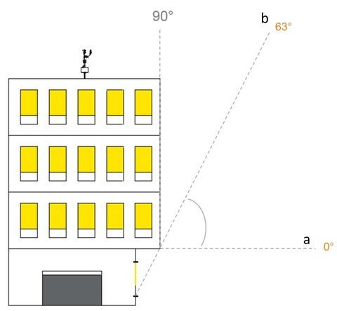
Venetian blind 90°/0° (type 1): It moves down with closed slats and up with horizontal slats (0° position).
It is also possible just to turn the slats (e.g. to prevent glare).
Venetian blind 90°/- 90° (type 2): It moves down with closed slats and also up with closed slats (rotated
inwardly). It is also possible just to turn the slats (e.g. to prevent glare).
Venetian blind 3 EL 90°/0° (type 3): It moves down with slats at an angle of 45° and up with horizontal slats
(0° position). It is also possible just to turn the slats (e.g. to prevent glare).
Louver (tilt only): The slats can only be turned here (no pull cord). The blind moves neither upwards nor
downwards.
Screen: This type of awning behaves like a roller shutter, moving just up and down. However, it is made of
textile material and must therefore be protected from outdoor weather influences. It may, for example,
require a wind brace at wind speeds above 6 m/s. The wind values should be obtained from the respective
awning manufacturer. Somfy accepts no liability for incorrect setups.
Drop arm awning: This is also made of textile material and only moves up and down, although not parallel
to the façade. A boom is used to extend the cloth into a 45° position relative to the façade.
Roller Shutter: Only moves up (0 % position) and down (100 % position).
Markisolette: A textile motorized product that first moves downwards parallel to the façade until it reaches
around half way, when it is then moved into a 45° angle relative to the façade by extending a boom. Only
moves up and down.
Folding arm awning: With folding arm awnings, the awning cloth of two or more arms is moved and ten-
sioned. The awning cloth can therefore fail in the horizontal direction, although a slight inclination is generally
set to prevent this. With the jointed-arm approach, the awning arms are angled when retracted and out-
stretched when extended.
Vertical fixed louvers (tilt only): This is a blind-based system that can only be turned vertically.
ZIP Screen: Behaves like a screen but is significantly more wind-resistant due to the zipper principle on the
left-hand and right-hand side of the motorized product. A wind brace is used for speeds above approximately
30 m/s (please contact your manufacturer). Somfy accepts no liability for incorrect setups.
Window opened outwards: With electric drive for opening and closing outwards. When setting the other
parameters, please note that 0 % corresponds to the closed position and 100 % to the opened position. In
the “Standard position” menu, this default setting can nevertheless be inverted.
End products/motorized products used indoors:
Venetian blind 90°/0°: It moves down with closed slats and up with horizontal slats (0° position). It is also
possible just to turn the slats (e.g. to prevent glare).
Venetian blind 90°/- 90°: It moves down with closed slats and up with closed slats, too (rotated inwardly). It
is also possible just to turn the slats (e.g. to prevent glare).
Venetian blind DCE 90°/- 90°: The running speed is regulated by the incremental position encoder technol-
ogy employed in the drive. This produces a very attractive façade and has a positive impact on reducing
operating noises.
H Only applies to drives of the type "Somfy Concept 25 DCE".
Interior Roller blind: Made of textile material and behaves like a roller shutter, i.e. just moving up and down.
Seite 9animeo IB+
4 Zone/8 Zone TouchBuco BACnet 2020/04/30
Interior Plisseé: Made of textile material and behaves like a roller shutter, i.e. just moving up and down.
Interior Venetian blind 90°/- 90°: This is a blind-based system that moves vertically and can be turned.
Interior curtain: With electric drive for opening and closing interior curtains and shades.
Window opened inwards: With electric drive for opening and closing inwards. When setting the other
parameters, please note that 0 % corresponds to the closed position and 100 % to the opened position. In
the “Standard position” menu (s. chapter 6.5.1.4), this default setting can nevertheless be inverted.
1.13 Set Run Time
The runtime is the time required by an end product/motorized product (roller shutters, Venetian blinds, etc.)
to move from its uppermost position (0 %) to its lowermost position (100 %) and vice versa. With windows,
the runtime is from fully open (100 %) to fully closed (0 %). The runtime is important to ensure that an end
product/motorized product can also be moved to an intermediate position (defined in percent from 0 % to
100 %).
H In the case of large/long motorized products, the runtime during downward travel can deviate from the
runtime for upward travel by several seconds (total distance covered by motorized product moving up and
down).
When using end products/motorized products with turning (e.g. Venetian blinds): If a position and an angle
are to be approached, the runtime must be entered very accurately, as the rotation for the angle only starts
once the runtime entered has elapsed.
If there are motorized products of varying lengths within a given zone, you must enter the longest time first.
You can make precision adjustments for the shorter motorized products in this zone later under "Settings".
When exiting the screen, these settings are automatically sent to the motor controllers of the corresponding
zone.
1.14 Set Tilt Time
The angle is the time required by a Venetian blind to turn the slats from fully closed to fully open. This time is
typically in the range from 0.8 to 2 seconds.
The right angle needs to be determined. Three test commands are available for this: 90°, 45° and 0°.
Interior Exterior
Test the commands one after the other. If necessary, alter the angle until optimum results are achieved for
the three angles. Recommended: Start at 1.5 seconds and adjust the value in 0.1 second steps. For exam-
ple, if 45° is more like 30° during testing, reduce it by 0.1 seconds. If 45° is more like 70° during testing,
increase it by 0.1 seconds.
When exiting the screen, these parameters are automatically sent to the motor controllers of the correspond-
ing zone.
Seite 10animeo IB+
4 Zone/8 Zone TouchBuco BACnet 2020/04/30
1.15 Copy Run/Tilt Times
You can copy the running time and angle from one zone to another zone. This can help save you time when
setting everything up.
"Source" represents the zone from which you are copying the setting. "Target" represents the zone to which
you are copying the setting. Select the source and target zone and then press "Copy" to confirm the copying
process. These parameters are sent to the motor controllers of the corresponding zone. The values can also
be modified individually here.
"Mech. Tol." designates the mechanical tolerance. This is only relevant for Venetian blinds. Depending on
the mechanical design, there may be a slight delay time between power being applied and the mechanical
movement actually starting (typically 0.2 to 0.3 seconds) when changing the direction of rotation. In the case
of roller shutters, however, this time should be 0 seconds.
The "Start Delay" function is primarily relevant for electronic drives. You should no longer alter this parameter
following careful and conscientious commissioning via the wizard. You can find further explanations on this
in the wizard under "End Product" in chapter 1.12.
1.16 Password
Assigning a password for the "Settings" menu
Assigning a password prevents third parties from making parameter changes (by mistake) while the system
is in operation. "somfy" is set as the default password. However, you can change the password here by
clicking on “Use Settings Password”.
1.17 Save Project
"New": You can create a new project file here. However, the number of project files is restricted to just four
due to the memory available.
"Delete": Select a file and delete it.
"Overwrite": You can overwrite an existing project file here. Simply highlight the file and select "Overwrite".
"Copy from/to USB": You can copy project files from and to a USB stick here. To avoid mistakes/confusion,
we recommend creating just one project file.
"Standard project file": Following a power cut, this file is automatically loaded after approximately 2 minutes.
Info: A system that has not yet been configured would obviously not start up automatically.
2 Home
You are in the main screen. You can use the menu bar on the left of the screen to access further settings
and options. You can tell which menu you are currently viewing by the white background, which also has a
vertical yellow pattern.
The "HOME" menu shows the current status of the individual zones (zone 1 to zone 4/8): The active function
and the position of the end products/motorized products. You can access the "Dashboard" via the arrow at
the bottom right. You can gain detailed information on all functions here.
You can adjust the zones individually in the "CONTROL" menu: Up, down, stop, intermediate position (my)
and freely definable position. You can also lock/unlock the zones, as well as activating/deactivating the
automatic sun-tracking system.
In the "SENSORS" menu, you can see which sensor inputs are connected, as well as the current sensor values.
Seite 11animeo IB+
4 Zone/8 Zone TouchBuco BACnet 2020/04/30
In the "LOG" menu, current events such as switching commands, sensor values and system faults are rec-
orded over an extended time period (up to a maximum of 3 months).
The "SETTINGS" menu takes you to further configurations. This menu can be protected with a password.
2.1 Dashboard
This menu provides you with up-to-date information on all functions of the selected zone. In the left-hand
half, you can see which zone you are currently working on and what type of motorized product you are deal-
ing with. The right half shows all available functions. They are listed in order of priority (top priority first). You
can recognize the selected functions by their yellow circle. When a function is active, the circle is filled.
All functions are sorted by priority from top to bottom:
• Alarm (the end products/shades are locked in the safety position)
• Lock (only low-priority functions are locked)
• Error (errors in the sensor technology are displayed)
• Wind (the end products/shades are locked in the safety position)
• Snow/Frost/Ice/Rain (the end products/shades are locked in the safety position)
• Lock Timer (manual Control and low-priority functions are locked for a certain time)
• Manual (local operation via button/TouchBuco is active)
• Timer (scheduled switching commands)
• Block Heat (power save function)
• Solar Heating (power save function)
• Maintain Heat (power save function)
• Cooling (power save function)
• Sun Protection (convenience function)
If multiple functions are active at the same time (for example wind and timer), only the function with the high-
est priority will be executed.
3 Control
3.1 Control
Standard: You can move the motorized products up and down using the up/down arrows. The stop button
allows you to stop the motorized products and the "my" button allows you to move them to the intermediate
position set (please refer to "Settings/Options", chapter 6.5).
Advanced: In this section, you can enter the precise position in per cent. In the case of Venetian blinds, you
can specify the angle in degrees. With roller shutters and Venetian blinds, 0 % corresponds to the raised
position, while with windows it means "closed". The set position is approached using the "Go to Position"
function.
Zone unlocked/locked: You can lock the zone entirely, for example to clean the windows, so that neither
local operation nor automatic control is possible. The zone can nevertheless be controlled using the
TouchBuco by means of safety commands.
Simply press the button again to release the function.
Sun enabled: You can use this button to switch the sun function on and off if the sun function is used for this
zone.
You can access the menu in order to control all zones together by using the grey arrows.
Seite 12animeo IB+
4 Zone/8 Zone TouchBuco BACnet 2020/04/30
3.2 Control all
Standard all: Here, you can move the motorized products in all zones selected up and down using the
up/down arrows. The stop button allows you to stop the motorized products and the "my" button allows you
to move them to the intermediate position set (please refer to "Settings/Options").
Advanced all: In this section, you can enter the precise position value as a percentage for all zones selected.
In the case of Venetian blinds, you can specify the angle in degrees. With roller shutters and Venetian blinds,
0 % corresponds to the raised position, while with windows it means "closed". The set position for all zones
is approached using the "Go to Position" function.
Zone unlocked/locked: You can lock the zone entirely, for example to clean the windows, so that neither
local operation nor automatic control is possible. The zone can nevertheless be controlled using the
TouchBuco by means of safety commands.
Simply press the button again to release the function.
Sun enabled: You can use this button to switch the sun function on and off if the sun function is used for this
zone.
3.3 Control all settings
Control zones used: Here you can select the zones to be controlled via "Control All".
4 Sensors
In this section, all sensors which are connected and in use are displayed as icons together with their current
measured values. The numbering from 1 to 8 indicates the number of the sensor type used.
Sensor errors are displayed by means of different symbols. This can be caused by various factors:
"-" Unused sensor.
"C" Sensor is selected in sensor menu but sensor is not available/connected.
"*" Sensor is not selected in sensor menu but sensor is available/connected.
"S" Sensor or wiring short-circuited.
"!" Communication to the sensor station impaired or interrupted (check connecting lines).
Please contact your specialist if you are not sure or require assistance.
4.1 Outside
In this section, all sensors which are connected and in use are displayed as icons together with their current
measured values. The numbering from 1 to 8 indicates the quantity and type of sun sensors used.
Sensor errors are displayed by means of different symbols. This can be caused by various factors:
"-" Unused sensor.
"C" Sensor is selected in sensor menu but sensor is not available/connected.
"*" Sensor is not selected in sensor menu but sensor is available/connected.
"S" Sensor or wiring short-circuited.
"!" Communication to the sensor station impaired or interrupted (check connecting lines).
Please contact your specialist if you are not sure or require assistance.
Seite 13animeo IB+
4 Zone/8 Zone TouchBuco BACnet 2020/04/30
4.2 Inside
In this section, all sensors which are connected and in use are displayed as icons together with their current
measured values. The numbering from 1 to 4 indicates the quantity of inside sensors used.
Sensor errors are displayed by means of different symbols. This can be caused by various factors:
"-" Unused sensor.
„C“ Temperature sensor is selected in sensor menu but sensor is not available/connected.
"*" Temperature sensor is not selected in sensor menu but sensor is available/connected.
"S" Temperature sensor or wiring short-circuited.
"!" Communication to the inside sensor box impaired or interrupted (check connecting lines).
Please contact your specialist if you are unsure or require assistance.
5 Log
The log is broken down into three categories: Event, sensors, error. It is stored for a maximum of 3 months.
Navigation:
Tap the desired category. You can use the white forward and backward arrows (located at the bottom in the
yellow area) to navigate through the recordings. To return to the main menu, simply tap the arrow at the top
left.
5.1 Event
All functional modifications are recorded per zone with their respective status. This display is useful when
troubleshooting. For example, if the delay times for the sun protection functions are set too short, too many
travel commands may potentially be triggered during changeable weather conditions. System behavior of
this kind can be detected by using this display.
5.2 Sensors
All measured values are recorded per sensor. Touch the respective sensor icon to read the accompanying
information. In the case of sun and temperature sensors, the mean average is transferred every 10 minutes.
In the case of wind, the highest value measured within a 10-minutes window is displayed. In the case of rain,
the system indicates whether or not it rained within a 10-minutes time period.
5.3 Error
If an error is displayed, please get in touch with your specialist immediately.
5.4 Export
This function enables you to save the protocol files on a USB stick.
Seite 14animeo IB+
4 Zone/8 Zone TouchBuco BACnet 2020/04/30
6 Settings
Alarm, Rain/Snow, Frost/Ice, Wind and Lock Timer are safety functions. When enabling individual safety
functions, the animeo IB+ or Smoove UNO IB+ Motor Controllers are locked for further operator commands
(local operation via buttons, radio functions, etc.) and low-priority automatic commands. The "IB" LED on the
motor controller lights up red to indicate that commands have been locked.
6.1 Security
6.1.1 Alarm
An alarm can be triggered via the separate floating input. The alarm function has top priority and, in the
event of an alarm signal, further operator commands (local operation via buttons, radio functions, etc.), as
well as all automatic commands are locked. The behavior of the end products/motorized products in a zone
is defined in the event of an alarm and when the alarm is terminated. The "IB" LED on the motor controller
lights up red to indicate that commands have been locked.
You can navigate through the setting using the grey "forward" and "backward" arrows.
To enable the alarm function you need to move the slider to the right.
Settings:
ALARM ON Position of the end product/motorized product in the event of an alarm signal
Lock Only: The end products/motorized products in a zone stop moving and low-priority manual and auto-
matic commands are locked.
Up Priority: The end products/motorized products in a zone move to the upper end limit and low-priority man-
ual and automatic commands are locked.
Down Priority: The end products/motorized products in a zone move to the lower end limit and low-priority
manual and automatic commands are locked.
ALARM OFF Position of the end product/motorized product once an alarm signal has been termi-
nated
H This function requires the running times and angles to have been programmed for the end products/
motorized products.
No Action: A travel command is not issued until the status of a different function is changed (e.g. sun).
Standard: The end products/motorized products move to the standard position. The standard position only
needs to be defined once under "Options/System Settings".
Position: The end products/motorized products are moved to an adjustable position here (%) or, in the case
of Venetian blinds, set to an adjustable angle (°).
My Position: The end products/motorized products are moved to the intermediate position programmed in
the motor controller.
Seite 15animeo IB+
4 Zone/8 Zone TouchBuco BACnet 2020/04/30
6.1.2 Rain/Snow
This function is used to protect end products/shades from precipitation for safety reasons. In the event of a
rain/snow alarm, further operator commands (local operation via buttons, radio control, etc.) and low-priority
automatic commands are locked. The "IB" LED on the Motor Controller lights up red to indicate that com-
mands have been locked.
H Snow can only be detected when an outdoor temperature sensor has been fitted and enabled. Without an
outdoor temperature sensor, all precipitation is simply classed as rain.
The rain function is activated if the precipitation lasts longer than the "Delay Time On" specified. If the out-
side temperature is less than 4° C, the system assumes that it is snowing. The behavior of the motorized
product in the event of rain and snow can be adjusted. The rain function is enabled again when no further
precipitation is measured following elapse of the "Delay Time Off".
You can navigate through the setting using the grey "forward" and "backward" arrows.
Enabling the function: To enable the Rain/Snow function, you need to move the slider to the right.
Setting the Rain/Snow function:
Delay time: Adjustment range "On" from 0 to 60 seconds. Adjustment range "Off" from 0 to 255 minutes.
Rain/Snow On:
Lock Only The end products/shades in a zone stop moving and low-priority manual and automatic com-
mands are locked.
Up Priority The end products/shades in a zone move to the upper end limit and low-priority manual and
automatic commands are locked.
Down Priority The end products/shades in a zone move to the lower end limit and low-priority manual and
automatic commands are locked.
6.1.3 Frost/Ice
This function is used to protect end products/shades from frost (cold) or ice (precipitation + cold) for safety
reasons. In the event of a frost/ice alarm, further operator commands (local operation via buttons, radio con-
trol, etc.) and low-priority automatic commands are locked. The "IB" LED on the Motor Controller lights up
red to indicate that commands have been locked.
The frost and ice functions cannot be enabled at the same time (either frost or ice). Both functions are ena-
bled when the temperature exceeds the threshold set by + 2° C.
Frost
This function is activated if the outside temperature remains below the threshold for longer than the "Delay
Time On" specified. The behavior of the end products/shades in the event of frost can be adjusted. The func-
tion is released as soon as the "Delay Time Off" has elapsed. This starts counting as soon as the tempera-
ture exceeds the threshold set.
Ice
This function is activated if the outside temperature remains below the threshold for longer than the "Delay
Time On" specified and if precipitation has been registered during the period of the "Rain History" set. The
behavior of the end products/shades in the event of ice can be adjusted. The function is released as soon as
the "Delay Time Off" has elapsed. This starts counting as soon as the temperature rises 2° C above the
threshold set. The "Delay Time Off" can be set to a maximum of 3,000 minutes. This function can be manu-
ally reset.
You can navigate through the setting using the grey "forward" and "backward" arrows.
Seite 16animeo IB+
4 Zone/8 Zone TouchBuco BACnet 2020/04/30
Enabling the function: To enable the Frost or Ice function, you need to move the "Frost/Ice" slider to the
right.
Setting the Frost/Ice function:
Threshold "On": Adjustment range from 0 °C to 40 °C.
Delay time: Adjustment range "On" from 0 to 255 seconds. Adjustment range "Off" from 0 to 3000 minutes.
Rain History (only for ice function): Adjustment range from 0 to 255 hours.
Frost/Ice On:
Lock Only The end products/shades in a zone stop moving and low-priority manual and automatic com-
mands are locked.
Up Priority The end products/shades in a zone move to the upper end limit and low-priority manual and
automatic commands are locked.
Down Priority The end products/shades in a zone move to the lower end limit and low-priority manual and
automatic commands are locked.
6.1.4 Wind
Wind sensors used
This function is used to protect end products/motorized products from high wind speeds for safety reasons.
In the event of a wind alarm, further operator commands (local operation via buttons, radio control, etc.) and
automatic commands with low priority are locked. The "IB" LED on the motor controller lights up red to indi-
cate that commands have been locked. If the wind direction sensor is also installed, individual zones can be
protected from strong wind. In this case, the number of wind speed sensors can be minimized. The wind
direction sensor therefore only protects the selected zone, meaning that not all end products/motorized
products are moved to the safety position.
Wind function
If the measured wind speed is above the wind threshold for a period at least equal to the "Delay Time On",
the wind function is activated. The behavior of the end product/motorized product can be defined. The "delay
time off" starts counting as soon as the wind speed drops below the threshold. The function is released as
soon as the "delay time off" has elapsed.
Wind function for application ZIP screen
If the measured wind speed exceeds the "low wind" threshold for a period at least equal to the "delay time
on", the product can only be raised or stopped using the local control. If the measured wind speed exceeds
the "high wind" threshold for a period at least equal to the "delay time on", the product is moved to the
selected position. The behavior of the end product/motorized product can be defined. The "delay time off"
starts counting as soon as the wind speed drops below the threshold. The function is released as soon as
the "delay time off" has elapsed.
Wind Direction
This function is only possible when the wind direction sensor and at least one wind sensor are enabled. If the
measured wind speed is above the "Wind Direction" threshold for a period at least equal to the "Delay Time
On" and the wind direction is within the monitored range (from 0° to 360°, whereby 0° is due north), the wind
direction function is active. The behavior of the end product/motorized product is the same as with the wind
alarm. The "Delay Time Off" starts counting as soon as the wind speed drops below the threshold and the
wind is outside the monitored range. The function is enabled as soon as the "Delay Time Off" has elapsed
and the wind direction is no longer in the range specified.
You can navigate through the setting using the grey "forward" and "backward" arrows.
Enabling the functions: To enable the “Wind”/”Wind Direction” function, you need to slide the "Wind”/”Wind
Direction" slider to the right.
Seite 17animeo IB+
4 Zone/8 Zone TouchBuco BACnet 2020/04/30
Setting the wind and wind direction:
Selecting the wind sensors: When setting up the sensor system, you either selected the Compact Sensor
(just one wind sensor) or the Outside Sensor Box (up to two wind sensors). You now need to select which
wind sensor is to be used as reference for this zone. If two sensors are selected, the highest value of the two
is always used.
Threshold for wind and wind direction: Adjustment range from 2 m/s to 30 m/s.
Delay time wind and wind direction: Adjustment range "On" from 0 to 60 seconds. Adjustment range "Off"
from 0 to 255 minutes.
Wind On: Setting the behavior of the motorized product in the event of a wind alarm
Lock Only The end products/motorized products in a zone stop moving and low-priority manual and auto-
matic commands are locked.
Up Priority The end products/motorized products in a zone move to the upper end limit and low-priority
manual and automatic commands are locked.
Down Priority The end products/motorized products in a zone move to the lower end limit and low-priority
manual and automatic commands are locked.
Wind Direction Area: Specify the start and end of the range. The adjustment range is from 0° to 360°,
whereby 0° corresponds to due north.
6.1.5 Lock Timer
The "Lock Timer" function is used to move the end products/motorized products of an area to a position at a
certain time (adjustable), where they remain until enabled. By that time, further operator commands (local
operation via buttons, radio control, etc.) and low-priority automatic commands are locked. The "IB" LED on
the motor controller lights up red to indicate that commands have been locked.
Up to 6 switching commands can be set per week day (Monday to Sunday). Each switching command can
be freely defined. "Not Used" is displayed as standard, i.e. not set and not enabled. To save time, settings
from one day can be copied to another.
Enabling the function: The function is enabled when you move the slider to the right.
Setting a switching command with disabling function:
First select a day and then one of the six potential switching commands by clicking on the yellow icon. The
setting procedure always remains the same. To return to the main menu, simply press the arrow at the
bottom right.
Switching command options:
Not Used: The command has not been set or enabled.
On Time: The disabling function is active from this time onwards. The timing can either be a fixed time of the
day or be based on the dusk and dawn times (please see “Switching commands at dusk” for an explanation
on this). The behavior of the motorized product is defined after setting the timing:
Lock Only: The end products/motorized products in a zone stop moving and low-priority manual and auto-
matic commands are locked.
Up Priority The end products/motorized products in a zone move to the upper end limit and low-priority
manual and automatic commands are locked.
Seite 18animeo IB+
4 Zone/8 Zone TouchBuco BACnet 2020/04/30
Down Priority The end products/motorized products in a zone move to the lower end limit and low-priority
manual and automatic commands are locked.
Off Time: The disabling function is terminated from this time onwards. The switching time can either be a
fixed time of the day or be calculated automatically based on the dawn and dusk times (please see below for
an explanation on this). If desired, you can also specify the position to which the end products/motorized
products are to be moved once the lock time used has elapsed.
Switching commands at dusk:
H Longitude and latitude must be set for this function to work. This is performed in the menu “Location” (s.
chapter 6.5.1.1. Location)
The switching times are identical to the programmed sunrise and sunset times. You can also select from two
versions:
Diff time used: The switching time is offset from the sunset time, either positively or negatively.
Example: The sun rises at 5:39 am in Stuttgart on 18 May. The diff time used is set to -15 minutes, so the
switching command is executed at 5:24 am. You can enjoy the sunrise. Conversely, the sun sets at 9:02 pm
in Stuttgart on 18 May. The diff time used is set to + 15 minutes, so the switching action is only performed at
9:17 pm and you can enjoy the sunset.
Lock time used: The switching command is executed on the basis of the automatically calculated dawn and
dusk times, although not before a certain time in the morning and not after a certain time in the evening.
Example: Let us re-examine the above example. If the lock time used (summer time) is set to dawn at 7:00
am, the switching command will not be executed until 7:00 am rather than at 5:39 am. If the evening lock
time used is set to 8:00 pm, the switching command is already executed at 8:00 pm rather than at 9:17 pm.
During winter, when the sunrise may not occur until around 7:15 am, the lock time used of 7:00 am is disre-
garded, as the sunrise occurs after the lock time used.
Copying: Once you have set up a specific day (for example Monday), you can then copy this setting to other
days. To do so, simply select the day you wish to copy from the “Lock Timer” main menu (source) and then
hit "Copy". Now select the individual timers that you wish to copy to other days (you are still working on
Monday). Then highlight the days you wish to apply the settings to (target) and press "Copy" again. You can
also copy the setting to a different zone.
Now use the left arrow button to return the starting menu. If you tap on the other days, you can now see that
the copied setting has been applied.
6.1.6 Error
This sets the end position if an error is triggered.
Settings:
Position of the end product/motorized product in the event of an error signal ("Error On"):
Up Priority: The end products/motorized products in a zone move to the upper end limit. Manual and
automatic commands with low priority are locked.
Down Priority: The end products/motorized products in a zone move to the lower end limit. Manual and
automatic commands with low priority are locked.
Seite 19You can also read