Daikin MD5 Variable Frequency Drive Controller - OM 1191
←
→
Page content transcription
If your browser does not render page correctly, please read the page content below
Operations Manual          OM 1191
                                              Group: AAH

 Daikin MD5                                   Part Number: OM 1191
                                              Date: February 2013

 Variable Frequency Drive Controller

© 2013 Daikin Applied
Table of Contents

Safety .  .  .  .  .  .  .  .  .  .  .  .  .  .  .  .  .  .  .  .  .  .  .  .  .  .  .  .  .  .  .  .  .  .  .  .  .  . 4   Embedded Fieldbus  .  .  .  .  .  .  .  .  .  .  .  .  .  .  .  .  .  .  .  .  .  .  .  .  . 45
    Use of Warnings and Notes .  .  .  .  .  .  .  .  .  .  .  .  .  .  .  .  .  .  .  . 4                                     Overview  .  .  .  .  .  .  .  .  .  .  .  .  .  .  .  .  .  .  .  .  .  .  .  .  .  .  .  .  .  .  .  .  . 45
Control Panel .  .  .  .  .  .  .  .  .  .  .  .  .  .  .  .  .  .  .  .  .  .  .  .  .  .  .  .  .  .  .  . 5                 Control Interface  .  .  .  .  .  .  .  .  .  .  .  .  .  .  .  .  .  .  .  .  .  .  .  .  .  .  . 45
    MD5 HVAC Control Panel Features .  .  .  .  .  .  .  .  .  .  .  .  .  . 5                                                 Planning .  .  .  .  .  .  .  .  .  .  .  .  .  .  .  .  .  .  .  .  .  .  .  .  .  .  .  .  .  .  .  .  .  . 45
            General Display Features .  .  .  .  .  .  .  .  .  .  .  .  .  .  .  .  .  .  . 5                                 Mechanical and Electrical Installation–EFB .  .  .  .  .  .  . 46
            HVAC Control Panel Modes .  .  .  .  .  .  .  .  .  .  .  .  .  .  .  .  . 5                                       Communication Setup – EFB . . . . . . . . . . . . . . . . . . 48
Start Up .  .  .  .  .  .  .  .  .  .  .  .  .  .  .  .  .  .  .  .  .  .  .  .  .  .  .  .  .  .  .  .  .  .  .  .  . 8             Serial Communication Selection . . . . . . . . . . . . . 48
Application Macros .  .  .  .  .  .  .  .  .  .  .  .  .  .  .  .  .  .  .  .  .  .  .  .  .  .  . 9                                 Serial Communication Configuration  .  .  .  .  .  .  .  .  . 48
    Overview  .  .  .  .  .  .  .  .  .  .  .  .  .  .  .  .  .  .  .  .  .  .  .  .  .  .  .  .  .  .  .  .  .  . 9           Activate Drive Control Functions – EFB . . . . . . . . . . 50
            General Considerations .  .  .  .  .  .  .  .  .  .  .  .  .  .  .  .  .  .  .  . 9                                      Controlling the Drive .  .  .  .  .  .  .  .  .  .  .  .  .  .  .  .  .  .  .  .  .  . 50
            HVAC Default macro  .  .  .  .  .  .  .  .  .  .  .  .  .  .  .  .  .  .  .  .  .  . 11                                  Input Reference Select .  .  .  .  .  .  .  .  .  .  .  .  .  .  .  .  .  .  .  . 50
Parameters .  .  .  .  .  .  .  .  .  .  .  .  .  .  .  .  .  .  .  .  .  .  .  .  .  .  .  .  .  .  .  .  . 12                      Miscellaneous Drive Control .  .  .  .  .  .  .  .  .  .  .  .  .  .  .  . 51
    Parameter List .  .  .  .  .  .  .  .  .  .  .  .  .  .  .  .  .  .  .  .  .  .  .  .  .  .  .  .  . 12                          Relay Output Control  .  .  .  .  .  .  .  .  .  .  .  .  .  .  .  .  .  .  .  .  . 52
            Group 99: Start-Up Data . . . . . . . . . . . . . . . . . . . 12                                                         Analog Output Control  .  .  .  .  .  .  .  .  .  .  .  .  .  .  .  .  .  .  .  . 53
            Group 01: Operating Data  .  .  .  .  .  .  .  .  .  .  .  .  .  .  .  .  . 13                                           PID Control Setpoint Source  .  .  .  .  .  .  .  .  .  .  .  .  .  .  . 53
            Group 03: Actual Signals  .  .  .  .  .  .  .  .  .  .  .  .  .  .  .  .  .  . 17                                        Communication Fault .  .  .  .  .  .  .  .  .  .  .  .  .  .  .  .  .  .  .  .  . 53
            Group 04: Fault History  .  .  .  .  .  .  .  .  .  .  .  .  .  .  .  .  .  .  . 19                                Feedback from the Drive – EFB . . . . . . . . . . . . . . . . 54
            Group 10: Start/Stop/Dir .  .  .  .  .  .  .  .  .  .  .  .  .  .  .  .  .  .  . 20                                      Pre-Defined Feedback .  .  .  .  .  .  .  .  .  .  .  .  .  .  .  .  .  .  .  . 54
            Group 11: Reference Select .  .  .  .  .  .  .  .  .  .  .  .  .  .  .  . 21                                             Mailbox Read/Write  .  .  .  .  .  .  .  .  .  .  .  .  .  .  .  .  .  .  .  .  .  . 54
            Group 12: Constant Speeds .  .  .  .  .  .  .  .  .  .  .  .  .  .  .  . 24                                              Actual Value Scaling .  .  .  .  .  .  .  .  .  .  .  .  .  .  .  .  .  .  .  .  .  . 55
            Group 16: System Controls  .  .  .  .  .  .  .  .  .  .  .  .  .  .  .  . 26                                       Diagnostics – EFB .  .  .  .  .  .  .  .  .  .  .  .  .  .  .  .  .  .  .  .  .  .  .  .  .  . 56
            Group 20: Limits .  .  .  .  .  .  .  .  .  .  .  .  .  .  .  .  .  .  .  .  .  .  .  .  . 28                            Fault Queue for Drive Diagnostics .  .  .  .  .  .  .  .  .  .  . 56
            Group 21: Start/Stop . . . . . . . . . . . . . . . . . . . . . . 29                                                      Serial Communication Diagnostics .  .  .  .  .  .  .  .  .  .  . 56
            Group 22: Accel/Decel .  .  .  .  .  .  .  .  .  .  .  .  .  .  .  .  .  .  .  . 30                                Troubleshooting .  .  .  .  .  .  .  .  .  .  .  .  .  .  .  .  .  .  .  .  .  .  .  .  .  .  .  . 58
            Group 26: Motor Control .  .  .  .  .  .  .  .  .  .  .  .  .  .  .  .  .  .  . 31                                 BACnet Protocol Technical Data .  .  .  .  .  .  .  .  .  .  .  .  .  .  . 59
            Group 30: Fault Functions  .  .  .  .  .  .  .  .  .  .  .  .  .  .  .  .  . 32                                          Binary Input Object Instance Summary  .  .  .  .  .  .  . 59
            Group 31: Automatic Reset  .  .  .  .  .  .  .  .  .  .  .  .  .  .  .  . 33                                             Binary Output Object Instance Summary .  .  .  .  .  . 59
            Group 34: Panel Display . . . . . . . . . . . . . . . . . . . 34                                                         Binary Value Object Instance Summary .  .  .  .  .  .  . 60
            Group 36: Timed Functions  .  .  .  .  .  .  .  .  .  .  .  .  .  .  .  . 36                                             Analog Input Object Instance Summary .  .  .  .  .  .  . 60
            Group 53: EFB Protocol .  .  .  .  .  .  .  .  .  .  .  .  .  .  .  .  .  .  . 38                                        Analog Output Object Instance Summary  .  .  .  .  . 61
            Group 64: Load Analyzer .  .  .  .  .  .  .  .  .  .  .  .  .  .  .  .  .  . 39                                          Analog Value Object Instance Summary  .  .  .  .  .  . 61
            Group 81: PFA Control .  .  .  .  .  .  .  .  .  .  .  .  .  .  .  .  .  .  .  . 41                                      BACnet Quick-Start Sequence .  .  .  .  .  .  .  .  .  .  .  .  .  . 62
            Group 98: Options  .  .  .  .  .  .  .  .  .  .  .  .  .  .  .  .  .  .  .  .  .  .  . 44                                BACnet Device Address Rules .  .  .  .  .  .  .  .  .  .  .  .  .  . 63
                                                                                                                               Protocol Implementation Conformance Statement
                                                                                                                                  (PICS) .  .  .  .  .  .  .  .  .  .  .  .  .  .  .  .  .  .  .  .  .  .  .  .  .  .  .  .  .  .  .  .  . 64
                                                                                                                                     PICS Summary .  .  .  .  .  .  .  .  .  .  .  .  .  .  .  .  .  .  .  .  .  .  .  .  .  . 64
                                                                                                                                     Statement .  .  .  .  .  .  .  .  .  .  .  .  .  .  .  .  .  .  .  .  .  .  .  .  .  .  .  .  .  . 65
                                                                                                                               BACnet Object Definitions .  .  .  .  .  .  .  .  .  .  .  .  .  .  .  .  .  .  .  . 66
                                                                                                                                     Object/Property Support Matrix  .  .  .  .  .  .  .  .  .  .  .  .  . 66

2                                                                                                                                                                                                                            OM 1191
Table of Contents

Fieldbus Adapter .  .  .  .  .  .  .  .  .  .  .  .  .  .  .  .  .  .  .  .  .  .  .  .  .  .  .  . 67                 Technical Data .  .  .  .  .  .  .  .  .  .  .  .  .  .  .  .  .  .  .  .  .  .  .  .  .  .  .  .  .  . 82
    Overview  .  .  .  .  .  .  .  .  .  .  .  .  .  .  .  .  .  .  .  .  .  .  .  .  .  .  .  .  .  .  .  .  . 67         Ratings .  .  .  .  .  .  .  .  .  .  .  .  .  .  .  .  .  .  .  .  .  .  .  .  .  .  .  .  .  .  .  .  .  .  . 82
          Control interface .  .  .  .  .  .  .  .  .  .  .  .  .  .  .  .  .  .  .  .  .  .  .  .  . 67                          Symbols .  .  .  .  .  .  .  .  .  .  .  .  .  .  .  .  .  .  .  .  .  .  .  .  .  .  .  .  .  .  . 83
          Planning .  .  .  .  .  .  .  .  .  .  .  .  .  .  .  .  .  .  .  .  .  .  .  .  .  .  .  .  .  .  . 68                 Sizing .  .  .  .  .  .  .  .  .  .  .  .  .  .  .  .  .  .  .  .  .  .  .  .  .  .  .  .  .  .  .  .  . 83
    Communication Setup – FBA .  .  .  .  .  .  .  .  .  .  .  .  .  .  .  .  .  . 69                                      Derating .  .  .  .  .  .  .  .  .  .  .  .  .  .  .  .  .  .  .  .  .  .  .  .  .  .  .  .  .  .  .  .  .  . 83
          Serial Communication Selection . . . . . . . . . . . . . 69                                                             Temperature Derating .  .  .  .  .  .  .  .  .  .  .  .  .  .  .  .  .  .  .  .  . 83
          Serial communication configuration .  .  .  .  .  .  .  .  .  . 69                                                      Altitude Derating .  .  .  .  .  .  .  .  .  .  .  .  .  .  .  .  .  .  .  .  .  .  .  .  . 83
          Start/Stop Direction Control .  .  .  .  .  .  .  .  .  .  .  .  .  .  .  . 69                                          Single Phase Supply Derating .  .  .  .  .  .  .  .  .  .  .  .  .  . 83
          Input Reference Select .  .  .  .  .  .  .  .  .  .  .  .  .  .  .  .  .  .  .  . 69                             Control connections .  .  .  .  .  .  .  .  .  .  .  .  .  .  .  .  .  .  .  .  .  .  .  .  . 84
          System Control .  .  .  .  .  .  .  .  .  .  .  .  .  .  .  .  .  .  .  .  .  .  .  .  .  . 70                          Control Connection Specifications .  .  .  .  .  .  .  .  .  .  . 84
          Relay Output Control  .  .  .  .  .  .  .  .  .  .  .  .  .  .  .  .  .  .  .  .  . 70                                  Control Cables .  .  .  .  .  .  .  .  .  .  .  .  .  .  .  .  .  .  .  .  .  .  .  .  .  . 84
          Analog Output Control  .  .  .  .  .  .  .  .  .  .  .  .  .  .  .  .  .  .  .  . 70                                    Drive’s Control Connection Terminals  .  .  .  .  .  .  .  . 85
          PID Control Setpoint Source  .  .  .  .  .  .  .  .  .  .  .  .  .  .  . 71                                             Control Terminal Descriptions .  .  .  .  .  .  .  .  .  .  .  .  .  .  . 85
          Communication Fault .  .  .  .  .  .  .  .  .  .  .  .  .  .  .  .  .  .  .  .  . 71                                    Serial Communications . . . . . . . . . . . . . . . . . . . . 86
    Feedback from the Drive – FBA .  .  .  .  .  .  .  .  .  .  .  .  .  .  .  . 71                                        Ambient Conditions .  .  .  .  .  .  .  .  .  .  .  .  .  .  .  .  .  .  .  .  .  .  .  .  . 87
    Diagnostics – FBA .  .  .  .  .  .  .  .  .  .  .  .  .  .  .  .  .  .  .  .  .  .  .  .  .  . 72                      Applicable Standards .  .  .  .  .  .  .  .  .  .  .  .  .  .  .  .  .  .  .  .  .  .  .  . 87
          Fault Handling  .  .  .  .  .  .  .  .  .  .  .  .  .  .  .  .  .  .  .  .  .  .  .  .  .  . 72              Appendix  .  .  .  .  .  .  .  .  .  .  .  .  .  .  .  .  .  .  .  .  .  .  .  .  .  .  .  .  .  .  .  .  .  . 88
          Serial Communication Diagnostics .  .  .  .  .  .  .  .  .  .  . 72                                              Daikin Applications  .  .  .  .  .  .  .  .  .  .  .  .  .  .  .  .  .  . . . . . . . . 88
    Generic Profile Technical Data .  .  .  .  .  .  .  .  .  .  .  .  .  .  .  .  . 73                                    MicroTech III Control Parameters: Factory  .  .  .  .  .  . 90
          Overview .  .  .  .  .  .  .  .  .  .  .  .  .  .  .  .  .  .  .  .  .  .  .  .  .  .  .  .  .  .  . 73          Communications Troubleshooting
          Control Word  .  .  .  .  .  .  .  .  .  .  .  .  .  .  .  .  .  .  .  .  .  .  .  .  .  .  . 73                 Instructions .  .  .  .  .  .  .  .  .  .  .  .  .  .  .  .  .  . . . . . . . . . . . . . . 90

          Status Word .  .  .  .  .  .  .  .  .  .  .  .  .  .  .  .  .  .  .  .  .  .  .  .  .  .  .  . 73                Possible Faults . . . . . . . . . . . . . . . . . . . . . . . . . . . . . 90

          Actual Values .  .  .  .  .  .  .  .  .  .  .  .  .  .  .  .  .  .  .  .  .  .  .  .  .  .  . 73
Diagnostics  .  .  .  .  .  .  .  .  .  .  .  .  .  .  .  .  .  .  .  .  .  .  .  .  .  .  .  .  .  .  .  . 74
    Diagnostic Displays .  .  .  .  .  .  .  .  .  .  .  .  .  .  .  .  .  .  .  .  .  .  .  .  . 74
          Correcting Faults  .  .  .  .  .  .  .  .  .  .  .  .  .  .  .  .  .  .  .  .  .  .  .  . 75
    Fault Resetting .  .  .  .  .  .  .  .  .  .  .  .  .  .  .  .  .  .  .  .  .  .  .  .  .  .  .  .  . 78
          Flashing Red Led .  .  .  .  .  .  .  .  .  .  .  .  .  .  .  .  .  .  .  .  .  .  .  . 78
          Red LED .  .  .  .  .  .  .  .  .  .  .  .  .  .  .  .  .  .  .  .  .  .  .  .  .  .  .  .  .  .  . 78
          History  .  .  .  .  .  .  .  .  .  .  .  .  .  .  .  .  .  .  .  .  .  .  .  .  .  .  .  .  .  .  .  . 78
    Correcting alarms . . . . . . . . . . . . . . . . . . . . . . . . . . . 78
    Alarm Listing  .  .  .  .  .  .  .  .  .  .  .  .  .  .  .  .  .  .  .  .  .  .  .  .  .  .  .  .  .  . 78
Maintenance .  .  .  .  .  .  .  .  .  .  .  .  .  .  .  .  .  .  .  .  .  .  .  .  .  .  .  .  .  .  .  . 80
    Maintenance Intervals .  .  .  .  .  .  .  .  .  .  .  .  .  .  .  .  .  .  .  .  .  .  . 80
    Heatsink .  .  .  .  .  .  .  .  .  .  .  .  .  .  .  .  .  .  .  .  .  .  .  .  .  .  .  .  .  .  .  .  .  . 80
    Drive Module Fan Replacement  .  .  .  .  .  .  .  .  .  .  .  .  .  .  . 80
    Capacitors .  .  .  .  .  .  .  .  .  .  .  .  .  .  .  .  .  .  .  .  .  .  .  .  .  .  .  .  .  .  .  . 81
    Control Panel .  .  .  .  .  .  .  .  .  .  .  .  .  .  .  .  .  .  .  .  .  .  .  .  .  .  .  .  .  . 81
          Cleaning .  .  .  .  .  .  .  .  .  .  .  .  .  .  .  .  .  .  .  .  .  .  .  .  .  .  .  .  .  .  . 81
          Battery  .  .  .  .  .  .  .  .  .  .  .  .  .  .  .  .  .  .  .  .  .  .  .  .  .  .  .  .  .  .  .  . 81

OM 1191                                                                                                                                                                                                                                  3
Safety
Safety

Use of Warnings and Notes
There are two types of safety instructions throughout this
manual:
                                                                                                DANGER
         • Notes draw attention to a particular condition or fact, or
           give information on a subject.                               Disconnect the internal EMC filter when installing the
                                                                        drive on an IT system (an ungrounded power system
         • Warnings caution you about conditions which can              or a high-resistance-grounded [over 30 ohm] power
           result in serious injury or death and/or damage to the       system).
           equipment. They also tell you how to avoid the danger.
           The warning symbols are used as follows:
                                                                                                DANGER
            Electricity warnings warn of hazards from electricity
            which can cause physical injury and/or damage to the        Do not attempt to install or remove EM1, EM3, F1 or
            equipment.                                                  F2 screws while power is applied to the drive’s input
                                                                        terminals.
            General warnings warn about conditions, other than
            those caused by electricity, which can result in physical
            injury and/or damage to the equipment                                               WARNING
                                                                        Do not control the motor with the disconnecting device
                                  DANGER                                (disconnecting means); instead, use the control panel
   The MD5 adjustable speed AC drive should ONLY be                     keys or commands via the I/O board of the drive. The
   installed by a qualified electrician.                                maximum allowed number of charging cycles of the DC
                                                                        capacitors (i.e. power-ups by applying power) is five in
                                                                        ten minutes.
                                  DANGER
   Even when the motor is stopped, dangerous voltage is                                         WARNING
   present at the power circuit terminals U1, V1, W1 (L1,
   L2, L3) and U2, V2, W2 (T1, T2 T3) and, depending on                 Never attempt to repair a malfunctioning MD5; contact
   the frame size, UDC+ and UDC-, or BRK+ and BRK-.                     the factory or your local Authorized Service Center for
                                                                        repair or replacement.

                                  DANGER
                                                                                                WARNING
   Dangerous voltage is present when input power is
   connected. After disconnecting the supply, wait at least             The MD5 will start up automatically after an input
   5 minutes (to let the intermediate circuit capacitors                voltage interruption if the external run command is on.
   discharge) before removing the cover.

                                                                                                WARNING
                                  DANGER                                .
   Even when power is switched off from the input terminals
   of the MD5, there may be dangerous voltage (from
   external sources) on the terminals of the relay outputs.

                                  DANGER
   When the control terminals of two or more drives are
   connected in parallel, the auxiliary voltage for these
   control connections must be taken from a single source
   which can either be one of the drives or an external
   supply.

4                                                                                                                       OM 1191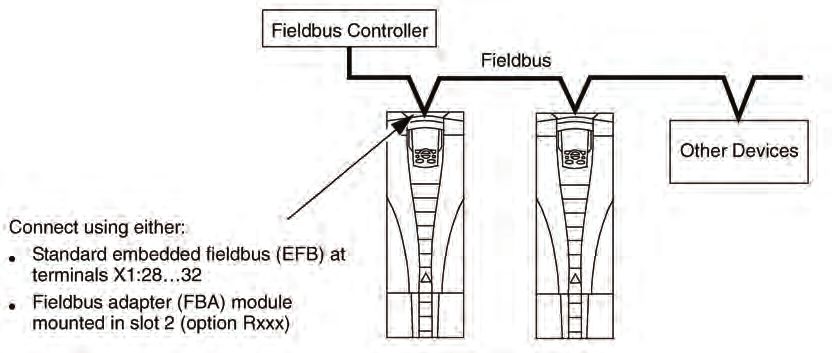
Control Panel
                                                                                                                        Control Panel

MD5 HVAC Control Panel Features
Figure 1: MD5 HVAC Control Panel Features

                          Status LED
                    (Green when normal,
                    if flashing or red,see
                         Diagnostics.)

                             UP

                         Soft Key 1

                                                                                            Soft Key 2
                           AUTO

                                                                                              HELP
                           DOWN                                                         (always available)

                            OFF                                                               HAND

   • Language selection for the display                       HVAC Control Panel Modes
   • Drive connection that can be made or detached at any
                                                              The HVAC control panel has several different modes for
     time
                                                              configuring, operating and diagnosing the drive. The modes
   • Start-up assistant to facilitate drive commissioning     are:
   • Copy function for moving parameters to other MD5
                                                                 • Standard Display Mode – Shows drive status
     drives
                                                                   information and operates the drive.
   • Backup function for saving parameter sets
                                                                 • Parameters Mode – Edits parameter values individually.
   • Context sensitive help
                                                                 • Start-up Assistant Mode – Guides the start-up and
   • Real-time clock                                               configuration.
                                                                 • Changed Parameters Mode – Shows changed
General Display Features                                           parameters.
Soft Key Functions                                               • Fault Logger Mode – Shows the drive fault history.
The soft key functions are defined by text displayed just        • Drive Parameter Backup Mode – Stores or uploads the
above each key.                                                    parameters.
                                                                 • Clock Set Mode – Sets the time and date for the drive.
Display Contrast
                                                                 • I/O Settings Mode – Checks and edits the I/O settings.
To adjust display contrast, simultaneously press        and
                                                                 • Alarm Mode – Reporting mode triggered by drive
       or         , as appropriate.
                                                                   alarms.
                                                              Standard Display Mode
                                                              Use the Standard Display Mode to read information on the
                                                              drive’s status and to operate the drive. To reach the Standard
                                                              Display Mode, press EXIT until the LCD display shows
                                                              status information.

OM 1191                                                                                                                         5
Control Panel
Control Panel

Status Information                                                             Operating the Drive
Top. The top line of the LCD display shows the basic status                    Auto/Hand – The very first time the drive is powered up, it is
information of the drive.                                                      in the auto control (AUTO) mode, and is controlled from the
        • HAND – Indicates that the drive control is local, that is,           Control terminal block X1.
          from the control panel.                                              To switch to hand control (HAND) and control the drive
        • AUTO – Indicates that the drive control is remote, such              using the control panel, press and hold the    or
          as the basic I/O (X1) or fieldbus.                                   button.
        •      – Indicates the drive and motor rotation status as                 • Pressing the HAND button switches the drive to hand
          follows:                                                                  control while keeping the drive running.
                                                                                  • Pressing the OFF button switches to hand control and
Table 1: Status Information                                                         stops the drive.
  Control Panel Display              Significance
                                                                               To switch back to auto control (AUTO), press and hold the
  Rotating arrow                     • Drive is running and at setpoint
                                                                                   button.
  (clockwise or counterclockwise)    • Shaft direction is forward or reverse
  Rotating dotted arrow blinking     Drive is running but not at setpoint
                                                                               Hand/Auto/Off – To start the drive press the HAND or
                                                                               AUTO buttons, to stop the drive press the OFF button.
                                     Start command is present, but motor
  Stationary dotted arrow            is not running. E.g. start enable is
                                     missing.                                  Reference – To modify the reference (only possible if the
                                                                               display in the upper right corner is in reverse video) press the
        • Upper right – shows the active reference.                            UP or DOWN buttons (the reference changes immediately).
Middle. Using Group 34: Panel Display, the middle of the                       The reference can be modified in the local control mode
LCD display can be configured to display:                                      (HAND/OFF), and can be parameterized (using Group 11:
   • One to three parameter values                                             Reference Select) to also allow modification in the remote
      – The default display shows                                              control mode.
      parameters 0103 (OUTPUT                                                  NOTE: The Start/Stop, Shaft direction and Reference
      FREQ) in percentages, 0104                                                     functions are only valid in local control (HAND/OFF)
      (CURRENT) in amperes and                                                       mode.
      0120 (AI1) in milliamperes.
      – Use parameters 3401, 3408, and 3415, see page 34,
         to select the parameters (from Group 01) to display.
         Entering “parameter” 0100 results in no parameter
         displayed. For example, if 3401 = 0100 and 3415
         = 0100, then only the parameter specified by 3408
         appears in the Control Panel display.
      – You can also scale each parameter in the display, for
         example, to convert the motor speed to a display of
         conveyor speed. Parameters 3402…3405 scale the
         parameter specified by 3401, parameters 3409…3412
         scale the parameter specified by 3408, etc.
   • A bar meter rather than one of the parameter values.
      – Enable bar graph displays
         using parameters 3404,
         3411 and 3418.
Bottom. The bottom of the LCD
display shows:
        • Lower corners – show the functions currently assigned
          to the two soft keys.
        • Lower middle – displays the current time (if configured
          to show the time).

6                                                                                                                                     OM 1191
Control Panel

Figure 2: Parameters Mode
To change the parameters, follow these steps:

          1            Select MENU to enter the main menu.

                       Select the Parameters mode with the UP/ DOWN buttons,
          2
                       and select ENTER to select the Parameters Mode.

                       Select the appropriate parameter group with the UP/
          3
                       DOWN buttons and select SEL.

                       Select the appropriate parameter in a group with the UP/
          4
                       DOWN buttons. Select EDIT to change the parameter.

                       Press the UP/DOWN buttons to change the parameter
          5
                       value.

                       Select SAVE to store the modified value or select
                       CANCEL to leave the set mode.
          6            • Any modifications not saved are cancelled.
                       • Each individual parameter setting is valid immediately
                         after pressing SAVE.

                       Select EXIT to return to the listing of parameter groups,
          7
                       and again to return to the main menu.

For detailed hardware description, see the Appendix on page 89.

NOTE: The current parameter value appears below the
      highlighted parameter.
           To view the default parameter value, press the UP/
           DOWN buttons simultaneously.
           The most typical and necessary parameters to
           change are parameter groups 99 Start-up data, 10
           Start/Stop/Dir, 11 Reference Select, 20 Limits, 21
           Start/Stop, 22 Accel/Decel, 26 Motor Control and 30
           Fault Functions.
           To restore the default factory settings, select the
           application macro HVAC Default.

OM 1191                                                                                        7
Start Up
Start Up

Figure 3: Start-Up By Changing the Parameters Individually
To change the parameters, follow these steps:

           1         Select MENU to enter the main menu.

                     Select the Parameters mode with the UP/DOWN buttons
           2
                     and select ENTER to select the Parameters mode.

                     Select the appropriate parameter group with the UP/
           3
                     DOWN buttons and select SEL

                     Select the appropriate parameter in a group with the UP/
           4         DOWN buttons. Select EDIT to change the parameter
                     value.

                     Press the UP/DOWN buttons to change the parameter
           5
                     value.

                     Select SAVE to store the modified value or select
           6         CANCEL to leave the set mode. Any modifications not
                     saved are cancelled.

                     Select EXIT to return to the listing of parameter groups,
           7
                     and again to return to the main menu.

To complete the control connections by manually entering the
parameters, see Parameters on page 12
For detailed hardware description, see the Technical Data on
page 82.
NOTE: The current parameter value appears below the
      highlighted parameter.
           To view the default parameter value, press the UP/
           DOWN buttons simultaneously.
           The most typical and necessary parameters to
           change are parameter groups 99 Start-up data, 10
           Start/Stop/Dir, 11 Reference Select, 20 Limits, 21
           Start/Stop, 22 Accel/Decel, 26 Motor Control and 30
           Fault Functions.
           To restore the default factory settings, select the
           application macro HVAC Default.

8                                                                                OM 1191
Application Macros
                                                                                                                                     Application Macros

Overview
Macros change a group of parameters to new, predefined          Table 2: Application/Macro Listing
values designed for specific applications. Use macros           This describes the following macros:
to minimize the need for manual editing of parameters.
                                                                        9902 Value          Macro
Selecting a macro sets (always use HVAC Defaults) all other
parameters to their default values, except:                                 1               HVAC Default**
                                                                            2               Supply Fan
   • Group 99: Start-up Data parameters (except parameter
                                                                            3               Return Fan
      9904)
                                                                            4                Condenser
   • The PARAMETER LOCK 1602
                                                                            6               Booster Pump
   • The PARAM SAVE 1607
                                                                            7               Pump Alternation
   • The COMM FAULT FUNC 3018 and COMM FAULT                                8               Internal Timer
      TIME 3019
                                                                            9               Internal Timer with Constant Speeds
   • The COMM PROT SEL 9802                                                 10              Floating Point
   • Groups 51…53 serial communication parameters                           11              Dual Setpoint PID
   • Group 29: Maintenance triggers                                         12              Dual Setpoint PID with Constant Speeds
After selecting a macro, additional parameter changes can be                13              E-bypass
made manually using the control panel.                                      14              Hand Control

Application macros are enabled by setting the value for                     15              E-Clipse

parameter 9902 APPLICMACRO. By default, HVAC Default             ** Daikin users must use the HVAC Defaults
(value 1) is the enabled macro.

General Considerations
The following considerations apply for all macros:
   • When using a direct speed reference in AUTO mode,
     connect the speed reference to analog input 1 (AI1),
     and provide the START command using digital input 1
     (DI1). In HAND/OFF mode, the control panel provides
     the speed reference and START command.
   • When using process PID, connect the feedback signal
     to analog input 2 (AI2). As a default, the control panel
     sets the Setpoint, but analog input 1 can be used
     as an alternate source. You can set up process PID
     using parameters (Group 40) or using the PID control
     assistant (recommended).

OM 1191                                                                                                                                           9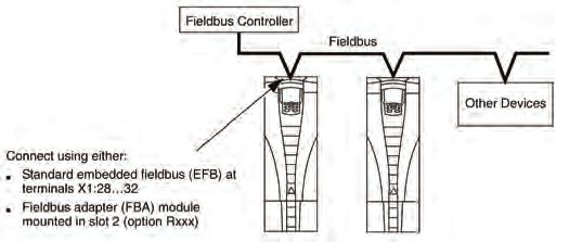
Application Macros
Application Macros

Figure 4: Selecting an application macro
To select a macro, follow these steps:

                     1   Select MENU to enter the main menu.

                         Select ASSISTANTS with the UP/DOWN buttons and
                     2
                         select ENTER.

                     3   Scroll to APPLICATION and select ENTER.

                         Select a macro with the UP/DOWN buttons and select
                     4
                         SAVE.

Restoring defaults
To restore the factory default settings, select the application
macro HVAC Default.
Control wiring
Each macro has specific requirements for control wiring. For
general details about the MD5 control wiring terminals, see
Control Terminal Descriptions on page 85. Specific wiring
requirements are included with each macro description.

10                                                                            OM 1191
Application Macros
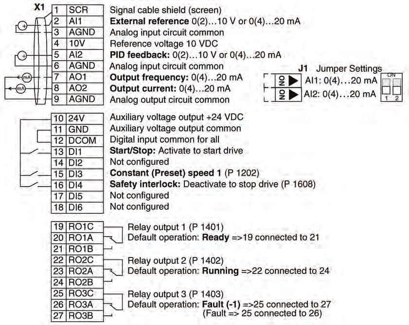
HVAC Default macro
This macro provides the factory default parameter settings for
the MD5-UH. Factory defaults can be restored at any time by
setting parameter 9902 to 1. The diagram below shows typical
wiring using this macro. When using direct speed reference
in AUTO mode or process PID, see General Considerations
on page 9.
Figure 5: MD5 HVAC Defaults
Table 3: Parameters Changed Relative to HVAC Default
Parameter Value Parameter Value
None (Default macro)
OM 1191 11Parameters
Parameters
Parameter List
The following parameters are important on Daikin applications. A summary is shown in Table 63: Parameter Settings on page
89. All other should not be adjusted. Parameter data is specific to MD5 firmware version 2.13.
Group 99: Start-Up Data
This group defines special Start-up data required to: NOTE: Parameters checked under the heading “S” can be
modified only when the drive is stopped.
• Set up the drive.
• Enter motor information
Table 4: Group 99: Start-up Data
Code Description Range Resolution Default S
0
9901 LANGUAGE 0…16 1
(ENGLISH)
Selects the display language.
0 = ENGLISH 1 = ENGLISH (AM) 2 = DEUTSCH 3 = ITALIANO 4 = ESPAÑOL 5 = PORTUGUES
6 = NEDERLANDS 7 = FRANCAIS 8 = DANSK 9 = SUOMI 10 = SVENSKA 11 = RUSSKI
12 = POLSKI 13 = TÜRKCE 14 = CZECH 15 = MAGYAR 16 = RESERVED
1(HVAC
9902 APPLIC MACRO -3…15, 31 1
DEFAULT)
Selects an application macro. Application macros automatically edit parameters to configure the MD5 for a particular application. See Application macros for
application macro descriptions.
1= HVAC DEFAULT 2= SUPPLY FAN 3= RETURN FAN 4= COOLING TOWER FAN 5= CONDENSER
6= BOOSTER PUMP 7= PUMP ALTERNATION 8= INTERNAL TIMER 9= INTERNAL TIMER WITH CONSTANT SPEEDS
10= FLOATING POINT 11= DUAL SETPOINT PID 12= DUAL SETPOINT PID WITH CONSTANT SPEEDS
13= E-BYPASS 14= HAND CONTROL 15= E-CLIPSE
31 = LOAD FD SET - FrontDrop parameter values as defined by the FlashDrop file. Parameter view is selected by parameter 1611 PARAMETER VIEW.
• FlashDrop is an optional device for fast copying of parameters to unpowered drives. FlashDrop allows easy customization of the parameter list, e.g.
selected parameters can be hidden. For more information, see MFDT-01 FlashDrop User’s Manual [3AFE68591074 (English)].
-1 = USER S1 SAVE, -3 = USER S2 SAVE - With these it is possible to save two different user parameter sets into the drive permanent memory for later use.
Each set contains parameter settings, including Group 99: START-UP DATA, and the results of the motor identification run.
0 = USER S1 LOAD, -2 = USER S2 LOAD - With these the user parameter sets can be taken back in use.
115…345 V 1V 230 V (US)
(200 V, US)
230…690 V 1V 460 V (US)
9905 MOTOR NOM VOLT
(400 V, US)
288…862 V 1V 575 V (US)
(600 V, US)
Defines the nominal motor voltage.
• Must equal the value on the motor rating plate.
• The MD5 cannot supply the motor with a voltage greater than the input power (mains) voltage.
0.15 · I2n …
9906 MOTOR NOM CURR 0.1 A 1.0 · I2n
1.5 · I2n
Defines the nominal motor current.
• Must equal the value on the motor rating plate.
• Range allowed: 0.15…1.5 · I2n (where I2n is drive current).
10.0…500.0 60.0 Hz
9907 MOTOR NOM FREQ 0.1 Hz
Hz (US)
Defines the nominal motor frequency.
• Range: 10…500 Hz (typically 50 or 60 Hz)
• Sets the frequency at which output voltage equals the MOTOR NOM VOLT.
• Field weakening point = Nom Freq · Supply Volt / Mot Nom Volt
50…30000 Size
9908 MOTOR NOM SPEED 1 rpm
rpm dependent
Defines the nominal motor speed.
• Must equal the value on the motor rating plate.
0.15…
9909 MOTOR NOM POWER 0.1 hp 1.0 · Pn
1.5 · Pn
Defines the nominal motor power.
• Must equal the value on the motor rating plate.
12 OM 1191Parameters
Parameters
Group 01: Operating Data
This group contains drive operating data, including actual signals. The drive sets the values for actual signals, based on
measurements or calculations. You cannot set these values.
Table 5: Group 01: Operating Data
Code Description Range Resolution Default S
-30000…
0101 SPEED & DIR 1 rpm —
30000 rpm
The calculated signed speed of the motor (rpm). The absolute value of 0101 SPEED & DIR is the same as the value of 0102 SPEED.
• The value of 0101 SPEED & DIR is positive if the motor runs in the forward direction.
• The value of 0101 SPEED & DIR is negative if the motor runs in the reverse direction.
0…30000
0102 SPEED 1 rpm —
rpm
The calculated speed of the motor (rpm).
0.0…500.0
0103 OUTPUT FREQ 0.1 Hz —
Hz
The frequency (Hz) applied to the motor.
0.0…1.5
0104 CURRENT 0.1 A —
× I2n
The motor current, as measured by the MD5.
-200.0…
0105 TORQUE 0.1% —
200.0%
Output torque. Calculated value of torque on motor shaft in % of motor nominal torque.
-1.5…1.5
0106 POWER 0.1 kW —
× Pn
The measured motor power in kW.
0…2.5 ×
0107 DC BUS VOLTAGE 1V —
VdN
The DC bus voltage in V DC, as measured by the MD5.
0…2.0 ×
0109 OUTPUT VOLTAGE 1V —
VdN
The voltage applied to the motor.
0.0…150.0
0110 DRIVE TEMP 0.1 °C —
°C
The temperature of the drive power transistors in degrees Celsius.
1
0.0…500.0
0.1 Hz / 1
0111 EXTERNAL REF Hz / —
rpm
0…30000
rpm
External reference, REF1, in rpm or Hz – units determined by parameter 9904.
0.0…100.0%
0112 EXTERNAL REF 2 (0.0…600.0% 0.1% —
for torque)
External reference, REF2, in %.
0113 CTRL LOCATION 0…2 1 —
Active control location. Alternatives are:
0 = LOCAL
1 = EXT1
2 = EXT2
0114 RUN TIME (R) 0…9999 h 1h —
The drive’s accumulated running time in hours (h).
• Can be reset by pressing UP and DOWN keys simultaneously when the control panel is in the Parameters mode.
0…65535
0115 KWH COUNTER (R 1 kWh —
kWh
The drive’s accumulated power consumption in kilowatt hours.
• The counter value is accumulated till it reaches 65535 after which the counter rolls over and starts again from 0.
• Can be reset by pressing UP and DOWN keys simultaneously when the control panel is in the Parameters mode. MD5-UH User’s Manual 1-83 Parameters
0.0…100.0%
0116 APPL BLK OUTPUT (0.0…600.0% 0.1% —
for torque)
Application block output signal. Value is from either:
• PFA control, if PFA Control is active, or
• Parameter 0112 EXTERNAL REF 2.
OM 1191 13Parameters
Table 5 continued: Group 01: Operating Data
000…111
0118 DI 1-3 STATUS (0…7 1 —
decimal)
Status of the three digital inputs.
• Status is displayed as a binary number.
• 1 indicates that the input is activated.
• 0 indicates that the input is deactivated.
000…111
0119 DI 4-6 STATUS (0…7 1 —
decimal)
Status of the three digital inputs.
• See parameter 0118 DI 1-3 STATUS.
0120 AI 1 0.0…100.0% 0.1% —
The relative value of analog input 1 in %.
0121 AI 2 0.0…100.0% 0.1% —
The relative value of analog input 2 in %.
000…111
0122 RO 1-3 STATUS (0…7 1 —
decimal)
Status of the three relay outputs.
• 1 indicates that the relay is energized.
• 0 indicates that the relay is de-energized.
000…111
0123 RO 4-6 STATUS (0…7 1 —
decimal)
Status of the three relay outputs. Available if OREL-01 Relay Output Extension Module is installed.
• See parameter 0122.
0.0…20.0
0124 AO 1 0.1 mA —
mA
The analog output 1 value in milliamperes.
0.0…20.0
0125 AO 2 0.1 mA —
mA
The analog output 2 value in milliamperes.
-1000.0…
0126 PID 1 OUTPUT 0.1% —
1000.0%
The PID controller 1 output value in %.
-100.0…
0127 PID 2 OUTPUT 0.1% —
100.0%
The PID controller 2 output value in %.
Unit and
scale
defined
0128 PID 1 SETPNT by par. — —
4006/4106
and
4007/4107
The PID 1 controller setpoint signal.
• Units and scale defined by PID parameters.
Unit and
scale
0129 PID 2 SETPNT defined by — —
par. 4206
and 4207
The PID 2 controller setpoint signal.
• Units and scale defined by PID parameters.
Unit and
scale
defined
0130 PID 1 FBK by par. — —
4006/4106
and
4007/4107
The PID 1 controller feedback signal.
• Units and scale defined by PID parameters.
14 OM 1191Parameters
Table 5 continued: Group 01: Operating Data
Unit and
scale
0131 PID 2 FBK defined by — —
par. 4206
and 4207
The PID 2 controller feedback signal.
• Units and scale defined by PID parameters.
Unit and
scale
defined
0132 PID 1 DEVIATION by par. — —
4006/4106
and
4007/4107
The difference between the PID 1 controller reference value and actual value.
• Units and scale defined by PID parameters.
Unit and
scale
0133 PID 2 DEVIATION defined by — —
par. 4206
and 4207
The difference between the PID 2 controller reference value and actual value.
• Units and scale defined by PID parameters.
0134 COMM RO WORD 0…65535 1 —
Free data location that can be written from serial link.
• Used for relay output control.
-32768…
0135 COMM VALUE 1 1 —
+32767
Free data location that can be written from serial link.
-32768…
0136 COMM VALUE 2 1 —
+32767
Free data location that can be written from serial link.
0137 PROCESS VAR 1 — 1 —
Process variable 1
• Defined by parameters in Group 34: Panel Display on page 34.
0138 PROCESS VAR 2 — 1 —
Process variable 2
• Defined by parameters in Group 34: Panel Display on page 34.
0139 PROCESS VAR 3 — 1 —
Process variable 3
• Defined by parameters in Group 34: Panel Display on page 34.
0.00…499.99
0140 RUN TIME 0.01 kh —
kh
The drive’s accumulated running time in thousands of hours (kh).
• Cannot be reset.
0…65535
0141 MWH COUNTER 1 MWh —
MWh
The drive’s accumulated power consumption in megawatt hours.
• The counter value is accumulated till it reaches 65535 after which the counter rolls over and starts again from 0.
• Cannot be reset.
0…65535
0142 REVOLUTION CNTR 1 Mrev —
Mrev
The motor’s accumulated revolutions in millions of revolutions.
• Can be reset by pressing UP and DOWN keys simultaneously when the control panel is in the Parameters mode.
0…65535
0143 DRIVE ON TIME HI 1 day —
days
The drive’s accumulated power-on time in days.
• Cannot be reset.
00:00:00…
0144 DRIVE ON TIME LO 1=2s —
23:59:58
The drive’s accumulated power-on time in 2 second ticks (30 ticks = 60 seconds).
• Shown in format hh.mm.ss.
• Cannot be reset.
OM 1191 15Parameters
Table 5 continued: Group 01: Operating Data
Par. 3501
= 1…3:
-10…200 °C
Par. 3501 =
0145 MOTOR TEMP 1 —
4: 0…5000
ohm Par.
3501 =
5…6: 0…1
Motor temperature in degrees Celsius / PTC resistance in ohms.
• Applies only if motor temperature sensor is set up.
-20.0…
0150 CB TEMP 1.0 °C —
150.0 °C
Temperature of the drive control board in degrees Celsius.
Note: Some drives have a control board (OMIO) that does not support this feature. These drives always show the constant value of 25.0 °C.
0153 MOT THERM STRESS 0.0…100.0% 0.1% —
Estimated rise of the motor temperature. Value equals to the estimated motor thermal stress as a percentage of the motor temperature trip level.
-32768…
0158 PID COMM VALUE 1 1 —
+32767
Data received from fieldbus for PID control (PID1 and PID2).
-32768…
0159 PID COMM VALUE 2 1 —
+32767
Data received from fieldbus for PID control (PID1 and PID2).
0.0…999.9
0174 SAVED KWH 0.1 kWh —
kWh
Energy saved in kWh compared to the energy used when the pump is connected directly to the supply. See the note on page 1-163.
• The counter value is accumulated till it reaches 999.9 after which the counter rolls over and starts again from 0.0.
• Can be reset with parameter 4509 ENERGY RESET (resets all energy calculators at the same time).
0…65535
0175 SAVED MWH 1 MWh — —
MWh
Energy saved in MWh compared to the energy used when the pump is connected directly to the supply. See the note on page 1-163.
• The counter value is accumulated till it reaches 65535 after which the counter rolls over and starts again from 0.
• Can be reset with parameter 4509 ENERGY RESET (resets all energy calculators at the same time).
0176 SAVED AMOUNT 1 0.0…999.9 0.1 —
Energy saved in local currency (remainder when the total saved energy is divided by 1000). See the note on page 1-163.
• To find out the total saved energy in currency units, add the value of parameter 0177 multiplied by 1000 to the value of parameter 0176.
Example:
0176 SAVED AMOUNT 1 = 123.4
0177 SAVED AMOUNT 2 = 5
Total saved energy = 5 ×1000 + 123.4 = 5123.4 currency units.
• The counter value is accumulated till it reaches 999.9 (the counter does not roll over).
• Can be reset with parameter 4509 ENERGY RESET (resets all energy calculators at the same time).
• Local energy price is set with parameter 4502 ENERGY PRICE.
0177 SAVED AMOUNT 2 0…65535 1 —
Energy saved in local currency in thousand currency units. Eg value 5 means 5000 currency units. See the note on page 1-163.
• The counter value is accumulated till it reaches 65535 (the counter does not roll over).
• See parameter 0176 SAVED AMOUNT 1.
0.0…6553.5
0178 SAVED CO2 0.1 tn —
tn
Reduction of carbon dioxide emissions in tons. See the note on page 1-163.
• The counter value is accumulated till it reaches 6553.5 (the counter does not roll over).
• Can be reset with parameter 4509 ENERGY RESET (resets all energy calculators at the same time).
• CO2 conversion factor is set with parameter 4507 CO2 CONV FACTOR.
16 OM 1191Parameters
Group 03: Actual Signals
This group monitors fieldbus communications.
Table 6: Group 03: Actual Signals
Code Description Range Resolution Default S
0301 FB CMD WORD 1 — 1 —
Read-only copy of the Fieldbus Command Word 1.
• The fieldbus command is the principal means for controlling the drive from a fieldbus controller. The command consists of two Command Words. Bit-coded
instructions in the Command Words switch the drive between states.
• To control the drive, using the Command Words, an external location (EXT1 or EXT2) must be active and set to COMM. (See parameters 1001 and 1002.)
The control panel displays the word in hex. For example, all zeros and a 1 in Bit 0 displays as 0001. All zeros and a 1 in Bit 15 displays as 8000.
Bit # 0301, FB CMD WORD 1 0302, FB CMD WORD 2
0 STOP FBLOCAL_CTL
1 START FBLOCAL_REF
2 REVERSE START_DISABLE1
3 LOCAL START_DISABLE2
4 RESET Reserved
5 EXT2 Reserved
6 RUN_DISABLE Reserved
7 STPMODE_R Reserved
8 STPMODE_EM Reserved
9 STPMODE_C Reserved
10 RAMP_2 Reserved
11 RAMP_OUT_0 REF_CONST
12 RAMP_HOLD REF_AVE
13 RAMP_IN_0 LINK_ON
14 RREQ_LOCALLOC REQ_STARTINH
15 TORQLIM2 OFF_INTERLOCK
0302 FB CMD WORD 2 — 1 —
Read-only copy of the Fieldbus Command Word 2.
• See parameter 0301.
0303 FB STS WORD 1 — 1 —
Read-only copy of the Status Word 1.
• The drive sends status information to the fieldbus controller. The status consists of two Status Words.
• The control panel displays the word in hex. For example, all zeros and a 1 in Bit 0 displays as 0001. All zeros and a 1 in Bit 15 displays as 8000.
Bit # 0303, FB STS WORD 1 0304, FB STS WORD 2
0 READY ALARM
1 ENABLED NOTICE
2 STARTED DIRLOCK
3 RUNNING LOCALLOCK
4 ZERO_SPEED CTL_MODE
5 ACCELERATE Reserved
6 DECELERATE Reserved
7 AT_SETPOINT CPY_CTL
8 LIMIT CPY_REF1
9 SUPERVISION CPY_REF2
10 REV_REF REQ_CTL
11 REV_ACT REQ_REF1
12 PANEL_LOCAL REQ_REF2
13 FIELDBUS_LOCAL REQ_REF2EXT
14 EXT2_ACT ACK_STARTINH
15 FAULT ACK_OFF_ILCK
0304 FB STS WORD 2 — 1 —
Read-only copy of the Status Word 2.
• See parameter 0303.
OM 1191 17Parameters
Table 6 continued: Group 03: Actual Signals
0305 FAULT WORD 1 — 1 —
Read-only copy of the Fault Word 1.
• When a fault is active, the corresponding bit for the active fault is set in the Fault Words.
• Each fault has a dedicated bit allocated within Fault Words.
• See section Fault listing on page 1-282 for a description of the faults.
• The control panel displays the word in hex. For example, all zeros and a 1 in Bit 0 displays as 0001. All zeros and a 1 in Bit 15 displays as 8000.
Bit # 0305, FAULT WORD 1 0306, FAULT WORD 2 0307, FAULT WORD 3
0 OVERCURRENT Obsolete EFB 1
1 DC OVERVOLT THERM FAIL EFB 2
2 DEV OVERTEMP OPEX LINK EFB 3
3 SHORT CIRC OPEX PWR INCOMPATIBLE SW
4 Reserved CURR MEAS USER LOAD CURVE
5 DC UNDERVOLT SUPPLY PHASE Reserved
6 AI1 LOSS ENCODER ERR Reserved
7 AI2 LOSS OVERSPEED Reserved
8 MOT OVERTEMP Reserved Reserved
9 PANEL LOSS DRIVE ID Reserved
10 ID RUN FAIL CONFIG FILE System error
11 MOTOR STALL SERIAL 1 ERR System error
12 CB OVERTEMP EFB CON FILE System error
13 EXT FAULT 1 FORCE TRIP System error
14 EXT FAULT 2 MOTOR PHASE System error
15 EARTH FAULT OUTP WIRING Param. setting fault
0306 FAULT WORD 2 — 1 —
Read-only copy of the Fault Word 2.
• See parameter 0305.
0307 FAULT WORD 3 — 1 —
Read-only copy of the Fault Word 3.
• See parameter 0305.
0308 ALARM WORD 1 — 1 —
• When an alarm is active, the corresponding bit for the active alarm is set in the Alarm Words.
• Each alarm has a dedicated bit allocated within Alarm Words.
• Bits remain set until the whole alarm word is reset. (Reset by writing zero to the word.)
• The control panel displays the word in hex. For example, all zeros and a 1 in Bit 0 displays as 0001. All zeros and a 1 in Bit 15 displays as 8000.
Bit # 0308, ALARM WORD 1 0309, ALARM WORD 2
0 OVERCURRENT Reserved
1 OVERVOLTAGE PID SLEEP
2 UNDERVOLTAGE ID RUN
3 DIR LOCK Reserved
4 IO COMM START ENABLE 1 MISSING
5 AI1 LOSS START ENABLE 2 MISSING
6 AI2 LOSS EMERGENCY STOP
7 PANEL LOSS ENCODER ERROR
8 DEVICE OVERTEMP FIRST START
9 MOTOR TEMP Reserved
10 Reserved USER LOAD CURVE
11 MOTOR STALL START DELAY
12 AUTORESET Reserved
13 AUTOCHANGE Reserved
14 PFA I LOCK Reserved
15 Reserved Reserved
0309 ALARM WORD 2 — 1 —
• See parameter 0308.Group 03: Actual Signals
18 OM 1191Parameters
Group 04: Fault History
This group stores a recent history of the faults reported by the drive.
Table 7: Group 04: Fault History
Code Description Range Resolution Default S
Fault codes
(panel
0401 LAST FAULT 1 0
displays as
text)
0 – Clear the fault history (on panel = NO RECORD).
n – Fault code of the last recorded fault. The fault code is displayed as a name. See section Fault listing on page 1-282 for the fault codes and names. The
fault name shown for this parameter may be shorter than the corresponding name in the fault listing, which shows the names as they are shown in the fault
display.
Date
dd.mm.yy
0402 FAULT TIME 1 / power- 1 day 0
on time in
days
The day on which the last fault occurred. Either as:
• A date – if real time clock is operating.
• The number of days after power on – if real time clock is not used, or was not set.
Time
0403 FAULT TIME 2 2s 0
hh:mm:ss
The time at which the last fault occurred. Either as:
• Real time, in format hh:mm:ss – if real time clock is operating.
• The time since power on (minus the whole days reported in 0402), in format hh:mm:ss – if real time clock is not used, or was not set.
• Format on the Basic Control Panel: The time since power on in 2-second ticks (minus the whole days reported in 0402). 30 ticks = 60 seconds. E.g. Value
514 equals 17 minutes and 8 seconds (= 514/30).
-32768…
0404 SPEED AT FLT 1 rpm 0
+32767
The motor speed (rpm) at the time the last fault occurred.
-3276.8…
0405 FREQ AT FLT 0.1 Hz 0
+3276.7
The frequency (Hz) at the time the last fault occurred.
0406 VOLTAGE AT FLT 0.0…6553.5 0.1 V 0
The DC bus voltage (V) at the time the last fault occurred.
0407 CURRENT AT FLT 0.0…6553.5 0.1 A 0
The motor current (A) at the time the last fault occurred.
-3276.8…
0408 TORQUE AT FLT 0.1% 0
+3276.7
The motor torque (%) at the time the last fault occurred.
0000…
0409 STATUS AT FLT 1 0
FFFF hex
The drive status (hex code word) at the time the last fault occurred.
000…111
0410 DI 1-3 AT FLT (0…7 1 0
decimal)
The status of digital inputs 1…3 at the time the last fault occurred.
000…111
0411 DI 4-6 AT FLT (0…7 1 0
decimal)
The status of digital inputs 4…6 at the time the last fault occurred.
As par.
0412 PREVIOUS FAULT 1 1 0
0401
Fault code of the second last fault. Read-only.
As par.
0413 PREVIOUS FAULT 2 1 0
0401
Fault code of the third last fault. Read-on
OM 1191 19Parameters
Group 10: Start/Stop/Dir
This group:
• Defines external sources (EXT1 and EXT2) for commands that enable start, stop and direction changes
• Locks direction or enables direction control.
To select between the two external locations use the next group (parameter 1102).
Table 8: Group 10: Start/Stop/Dir
Code Description Range Resolution Default S
1001 EXT1 COMMANDS 0…14 1 1 (DI1)
Defines external control location 1 (EXT1) – the configuration of start, stop and direction commands.
0 = NOT SEL – No external start, stop and direction command source.
1 = DI1 – Two-wire Start/Stop.
• Start/Stop is through digital input DI1 (DI1 activated = Start; DI1 de-activated = Stop).
• Parameter 1003 defines the direction. Selecting 1003 = 3 (REQUEST) is the same as 1003 = 1 (FORWARD).
2 = DI1,2 – Two-wire Start/Stop, Direction.
• Start/Stop is through digital input DI1 (DI1 activated = Start; DI1 de-activated = Stop).
• Direction control [requires parameter 1003 = 3 (REQUEST)] is through digital input DI2 (DI2 activated = Reverse; de-activated = Forward).
3 = DI1P,2P – Three-wire Start/Stop.
• Start/Stop commands are through momentary push-buttons (the P stands for “pulse”).
• Start is through a normally open push-button connected to digital input DI1. In order to start the drive, the digital input DI2 must be activated prior to the
pulse in DI1.
• Connect multiple Start push-buttons in parallel.
• Stop is through a normally closed push-button connected to digital input DI2.
• Connect multiple Stop push-buttons in series.
• Parameter 1003 defines the direction. Selecting 1003 = 3 (REQUEST) is the same as 1003 = 1 (FORWARD).
4 = DI1P,2P,3 – Three-wire Start/Stop, Direction.
• Start/Stop commands are through momentary push-buttons, as described for DI1P,2P.
• Direction control [requires parameter 1003 = 3 (REQUEST)] is through digital input DI3 (DI3 activated = Reverse; de-activated = Forward).
5 = DI1P,2P,3P – Start Forward, Start Reverse and Stop.
• Start and Direction commands are given simultaneously with two separate momentary push-buttons (the P stands for “pulse”).
• Start Forward command is through a normally open push-button connected to digital input DI1. In order to start the drive, the digital input DI3 must be
activated prior to the pulse in DI1.
• Start Reverse command is through a normally open push-button connected to digital input DI2. In order to start the drive, the digital input DI3 must be
activated during the pulse in DI2.
• Connect multiple Start push-buttons in parallel.
• Stop is through a normally closed push-button connected to digital input DI3.
• Connect multiple Stop push-buttons in series.
• Requires parameter 1003 = 3 (REQUEST).
6 = DI6 – Two-wire Start/Stop.
• Start/Stop is through digital input DI6 (DI6 activated = Start; DI6 de-activated = Stop).
• Parameter 1003 defines the direction. Selecting 1003 = 3 (REQUEST) is the same as 1003 = 1 (FORWARD).
7 = DI6,5 – Two-wire Start/Stop/Direction.
• Start/Stop is through digital input DI6 (DI6 activated = Start; DI6 de-activated = Stop).
• Direction control [requires parameter 1003 = 3 (REQUEST)] is through digital input DI5. (DI5 activated = Reverse; de-activated = Forward).
8 = KEYPAD – Control Panel.
• Start/Stop and Direction commands are through the control panel when EXT1 is active.
• Direction control requires parameter 1003 = 3 (REQUEST).
9 = DI1F,2R – Start/Stop/Direction commands through DI1 and DI2 combinations.
• Start forward = DI1 activated and DI2 de-activated.
• Start reverse = DI1 de-activated and DI2 activated.
• Stop = both DI1 and DI2 activated, or both de-activated.
• Requires parameter 1003 = 3 (REQUEST).
10 = COMM – Assigns the fieldbus Command Word as the source for the start/stop and direction commands.
• Bits 0, 1, 2 of Command Word 1 (parameter 0301) activates the start/stop and direction commands.
• See Fieldbus user’s manual for detailed instructions.
11 = TIMED FUNC 1. – Assigns Start/Stop control to Timed Function 1 (Timed Function activated = START; Timed Function de-activated = STOP).
See on page 35.
12…14 = TIMED FUNC 2…4 – Assigns Start/Stop control to Timed Function 2…4. See TIMED FUNC 1 above.
1002 EXT2 COMMANDS 0…14 1 1 (DI1)
Defines external control location 2 (EXT2) – the configuration of start, stop and direction commands.
• See parameter 1001 EXT1 COMMANDS above.
1
1003 DIRECTION 1…3 1
(FORWARD)
Defines the control of motor rotation direction.
1 = FORWARD – Rotation is fixed in the forward direction.
2 = REVERSE – Rotation is fixed in the reverse direction.
3 = REQUEST – Rotation direction can be changed on command.
20 OM 1191Parameters
Group 11: Reference Select
This group defines:
• How the drive selects between command sources
• Characteristics and sources for REF1 and REF2.
Table 9: Group 11: Reference Select
Code Description Range Resolution Default S
1102 EXT1/EXT2 SEL -6…12 1 0 (EXT1)
Defines the source for selecting between the two external control locations EXT1 or EXT2. Thus, defines the source for Start/Stop/Direction commands and
reference signals.
0 = EXT1 – Selects external control location 1 (EXT1).
• See parameter 1001 EXT1 COMMANDS for EXT1’s Start/Stop/Dir definitions.
• See parameter 1103, page 22 REF1 SELECT for EXT1’s reference definitions.
1 = DI1 – Assigns control to EXT1 or EXT2 based on the state of DI1 (DI1 activated = EXT2; DI1 de-activated = EXT1).
2…6 = DI2…DI6 – Assigns control to EXT1 or EXT2 based on the state of the selected digital input. See DI1 above.
7 = EXT2 – Selects external control location 2 (EXT2).
• See parameter 1002 EXT2 COMMANDS for EXT2’s Start/Stop/Dir definitions.
• See parameter 1106 REF2 SELECT for EXT2’s reference definitions.
8 = COMM – Assigns control of the drive via external control location EXT1 or EXT2 based on the fieldbus control word.
• Bit 5 of the Command Word 1 (parameter 0301) defines the active external control location (EXT1 or EXT2).
• See Fieldbus user’s manual for detailed instructions.
9 = TIMED FUNC 1 – Assigns control to EXT1 or EXT2 based on the state of the Timed Function (Timed Function activated = EXT2; Timed Function de-
activated = EXT1). See on page 35.
10…12 = TIMED FUNC 2…4 – Assigns control to EXT1 or EXT2 based on the state of the Timed Function. See TIMED FUNC 1 above.
-1 = DI1(INV) – Assigns control to EXT1 or EXT2 based on the state of DI1 (DI1 activated = EXT1; DI1 de-activated = EXT2).
-2…-6 = DI2(INV)…DI6(INV) – Assigns control to EXT1 or EXT2 based on the state of the selected digital input. See DI1(INV) above.
OM 1191 21Parameters
Table 9 continued: Group 11: Reference Select
0…17,
1103 REF1 SELECT 1 1 (AI1)
20…21
Selects the signal source for external reference REF1.
0 = KEYPAD – Defines the control panel as the reference source.
1 = AI1 – Defines analog input 1 (AI1) as the reference source.
2 = AI2 – Defines analog input 2 (AI2) as the reference source.
3 = AI1/JOYST – Defines analog input 1 (AI1), configured for joystick operation, as the
reference source.
• The minimum input signal runs the drive at the maximum reference in the reverse
direction. Define the minimum using parameter 1104.
• The maximum input signal runs the drive at maximum reference in the forward
direction. Define the maximum using parameter 1105.
• Requires parameter 1003 = 3 (REQUEST).
WARNING! Because the low end of the reference range commands full reverse
operation, do not use 0 V as the lower end of the reference range. Doing so means
that if the control signal is lost (which is a 0 V input) the result is full reverse operation.
Instead, use the following set-up so that loss of the analog input triggers a fault,
stopping the drive:
• Set parameter 1301 MINIMUM AI1 (1304 MINIMUM AI2) at 20% (2 V or 4 mA).
• Set parameter 3021 AI1 FAULT LIMIT to a value 5% or higher.
• Set parameter 3001 AIParameters
Table 9 continued: Group 11: Reference Select
0.0…500.0
Hz / 0.1 Hz / 0.0 Hz /
1104 REF1 MIN
0…30000 1 rpm 0 rpm
rpm
Sets the minimum for external reference 1.
• The minimum analog input signal (as a percent of the full signal in volts or amperes) corresponds to REF1 MIN in Hz/rpm.
•Parameter 1301 MINIMUM AI1 or 1304 MINIMUM AI2 sets the minimum analog input signal. Does not apply to Daikin MicroTech III applications.
• These parameters (reference and analog min. and max. settings) provide scale and offset adjustment for the reference.
0.0…500.0
60.0 Hz
Hz / 0.1 Hz /
1105 REF1 MAX (US) / 1800
0…30000 1 rpm
rpm (US)
rpm
Sets the maximum for external reference 1.
• The maximum analog input signal (as a percent of full the signal in volts or amperes) corresponds to REF1 MAX in Hz/rpm.
•Parameter 1302 MAXIMUM AI1 or 1305 MAXIMUM AI2 sets the maximum analog input signal. Does not apply to Daikin MicroTech III applications.
0…17, 19
1106 REF2 SELECT 1
19…21 (PID1OUT)
Selects the signal source for external reference REF2 .
0…17 – Same as for parameter 1103 REF1 SELECT.
19 = PID1OUT – The reference is taken from the PID1 output . See Group 40: PROCESS PID SET 1 and Group 41: PROCESS PID SET 2 . Does not apply
to Daikin MicroTech III applications .
20…21 – Same as for parameter 1103 REF1 SELECT
OM 1191 23Parameters
Group 12: Constant Speeds
This group defines a set of constant speeds. In general:
• You can program up to 7 constant speeds, ranging from 0…500 Hz or 0…30000 rpm.
• Values must be positive (No negative speed values for constant speeds).
• Constant speed selections are ignored if:
– The torque control is active, or
– The process PID reference is followed, or
– The drive is in local control mode, or
– PFA (Pump-Fan Alternation) is active.
Table 10: Group 12: Constant Speeds
Code Description Range Resolution Default S
1201 CONST SPEED SEL -14 …19 1 3 (DI3)
Defines the digital inputs used to select Constant Speeds. See general comments in introduction.
0 = NOT SEL – Disables the constant speed function.
1 = DI1 – Selects Constant Speed 1 with digital input DI1.
• Digital input activated = Constant Speed 1 activated.
2…6 = DI2…DI6 – Selects Constant Speed 1 with digital input DI2…DI6. See above.
7 = DI1,2 – Selects one of three Constant Speeds (1…3) using DI1 and DI2.
• Uses two digital inputs, as defined below (0 = DI de-activated, 1 = DI activated):
DI1 DI2 Function
0 0 No constant speed
1 0 Constant speed 1 (1202)
0 1 Constant speed 2 (1203)
1 1 Constant speed 3 (1204)
8 = DI2,3 – Selects one of three Constant Speeds (1…3) using DI2 and DI3.
• See above (DI1,2) for code.
9 = DI3,4 – Selects one of three Constant Speeds (1…3) using DI3 and DI4.
• See above (DI1,2) for code.
10 = DI4,5 – Selects one of three Constant Speeds (1…3) using DI4 and DI5.
• See above (DI1,2) for code.
11 = DI5,6 – Selects one of three Constant Speeds (1…3) using DI5 and DI6.
• See above (DI1,2) for code.
12 = DI1,2,3 – Selects one of seven Constant Speeds (1…7) using DI1, DI2 and DI3.
• Uses three digital inputs, as defined below (0 = DI de-activated, 1 = DI activated):
DI1 DI2 DI3 Function
0 0 0 No constant speed
1 0 0 Constant speed 1 (1202)
0 1 0 Constant speed 2 (1203)
1 1 0 Constant speed 3 (1204)
0 0 1 Constant speed 4 (1205)
1 0 1 Constant speed 5 (1206)
0 1 1 Constant speed 6 (1207)
1 1 1 Constant speed 7 (1208)
1 1 0 Constant speed 4 (1205)
0 1 0 Constant speed 5 (1206)
1 0 0 Constant speed 6 (1207)
0 0 0 Constant speed 7 (1208)
13 = DI3,4,5 – Selects one of seven Constant Speeds (1…7) using DI3, DI4 and DI5.
• See above (DI1,2,3) for code.
14 = DI4,5,6 – Selects one of seven Constant Speeds (1…7) using DI4, DI5 and DI6.
• See above (DI1,2,3) for code.
15…18 = TIMED FUNC 1…4 – Selects Constant Speed 1, Constant Speed 2 or the external reference, depending on the state of the Timed Function (1…4)
and constant speed mode. See parameter 1209 TIMED MODE SEL and on page 35.
19 = TIMED FUN1&2 – Selects a constant speed or the external reference, depending on the state of Timed Functions 1 & 2 and constant speed mode. See
parameter 1209 TIMED MODE SEL and .
-1 = DI1(INV) – Selects Constant Speed 1 with digital input DI1.
• Inverse operation: Digital input de-activated = Constant Speed 1 activated.
-2…- 6 = DI2(INV)…DI6(INV) – Selects Constant Speed 1 with digital input. See above.
24 OM 1191Parameters
Table 10 continued: Group 12: Constant Speeds
Code Description Range Resolution Default S
-7 = DI1,2(INV) – Selects one of three Constant Speeds (1…3) using DI1 and DI2.
• Inverse operation uses two digital inputs, as defined below (0 = DI de-activated, 1 = DI activated):
DI1 DI2 Function
1 1 No constant speed
0 1 Constant speed 1 (1202)
1 0 Constant speed 2 (1203)
0 0 Constant speed 3 (1204)
-8 = DI2,3(INV) – Selects one of three Constant Speeds (1…3) using DI2 and DI3.
• See above (DI1,2(INV)) for code.
-9 = DI3,4(INV) – Selects one of three Constant Speeds (1…3) using DI3 and DI4.
• See above (DI1,2(INV)) for code.
-10 = DI4,5(INV) – Selects one of three Constant Speeds (1…3) using DI4 and DI5.
• See above (DI1,2(INV)) for code.
-11 = DI5,6(INV) – Selects one of three Constant Speeds (1…3) using DI5 and DI6.
• See above (DI1,2(INV)) for code.
-12 = DI1,2,3(INV) – Selects one of seven Constant Speeds (1…7) using DI1, DI2 and DI3.
• Inverse operation uses three digital inputs, as defined below (0 = DI de-activated, 1 = DI activated):
DI1 DI2 DI3 Function
1 1 1 No constant speed
0 1 1 Constant speed 1 (1202)
1 0 1 Constant speed 2 (1203)
0 0 1 Constant speed 3 (1204)
-13 = DI3,4,5(INV) – Selects one of seven Constant Speeds (1…7) using DI3, DI4 and DI5.
• See above (DI1,2,3(INV)) for code.
-14 = DI4,5,6(INV) – Selects one of seven Constant Speeds (1…7) using DI4, DI5 and DI6.
• See above (DI1,2,3(INV)) for code.
2
1209 TIMED MODE SEL 1, 2 1
(CS1/2/3/4)
Defines timed function activated constant speed mode. Timed function can be used to change between the external reference and constant speeds when
parameter 1201 CONST SPEED SEL = 15…18 (TIMED FUNC 1…4) or 19 (TIMED FUN1&2).
1 = EXT/CS1/2/3
• If parameter 1201 = 15…18 (TIMED FUNC 1…4), selects an external speed when this timed function (1…4) is not active and selects Constant speed 1
when it is active.
TIMED FUNCTION 1…4 Function
0 External reference
1 Constant speed 1 (1202)
• If parameter 1201 = 19 (TIMED FUN1&2), selects an external speed when neither timed function is active, selects Constant speed 1 when only Timed
function 1 is active, selects Constant speed 2 when only Timed function 2 is active and selects Constant speed 3 when both Timed functions 1 and 2
are active.
TIMED FUNCTION 1 TIMED FUNCTION 2 Function
0 0 External reference
1 0 Constant speed 1 (1202)
0 1 Constant speed 2 (1203)
1 1 Constant speed 3 (1204)
2 = CS1/2/3/4
• If parameter 1201 = 15…18 (TIMED FUNC 1…4), selects Constant speed 1 when this timed function (1…4) is not active and selects Constant speed 2
when it is active.
TIMED FUNCTION 1…4 Function
0 Constant speed 1 (1202)
1 Constant speed 2 (1203)
• If parameter 1201 = 19 (TIMED FUN1&2), selects Constant speed 1 when neither timed function is active, selects Constant speed 2 when only Timed
function 1 is active, selects Constant speed 3 when only Timed function 2 is active and selects Constant speed 4 when both Timed functions 1 and 2
are active.
TIMED FUNCTION 1 TIMED FUNCTION 2 Function
0 0 Constant speed 1 (1202)
1 0 Constant speed 2 (1203)
0 1 Constant speed 3 (1204)
1 1 Constant speed 4 (1205)
OM 1191 25Parameters
Group 16: System Controls
This group defines a variety of system level locks, resets and enables.
Table 11: Group 16: System Controls
Code Description Range Resolution Default S
0 (NOT
1601 RUN ENABLE -6…7 1
SEL)
Selects the source of the run enable signal.
0 = NOT SEL – Allows the drive to start without an external run enable signal.
1 = DI1 – Defines digital input DI1 as the run enable signal.
• This digital input must be activated for run enable.
• If the voltage drops and de-activates this digital input, the drive will coast to stop and not start until the run enable signal resumes.
2…6 = DI2…DI6 – Defines digital input DI2…DI6 as the run enable signal.
• See DI1 above.
7 = COMM – Assigns the fieldbus Command Word as the source for the run enable signal.
• Bit 6 of the Command Word 1 (parameter 0301) activates the run disable signal.
• See fieldbus user’s manual for detailed instructions.
-1 = DI1(INV) – Defines an inverted digital input DI1 as the run enable signal.
• This digital input must be de-activated for run enable.
• If this digital input activates, the drive will coast to stop and not start until the run enable signal resumes.
-2…-6 = DI2(INV)…DI6(INV) – Defines an inverted digital input DI2…DI6 as the run enable signal.
• See DI1(INV) above.
1604 FAULT RESET SEL -6…8 1 0 (KEYPAD)
Selects the source for the fault reset signal. The signal resets the drive after a fault trip if the cause of the fault no longer exists.
0 = KEYPAD – Defines the control panel as the only fault reset source.
• Fault reset is always possible with control panel.
1 = DI1 – Defines digital input DI1 as a fault reset source.
• Activating the digital input resets the drive.
2…6 = DI2…DI6 – Defines digital input DI2…DI6 as a fault reset source.
• See DI1 above.
7 = START/STOP – Defines the Stop command as a fault reset source.
• Do not use this option when fieldbus communication provides the start, stop and direction commands.
8 = COMM – Defines the fieldbus as a fault reset source.
• The Command Word is supplied through fieldbus communication.
• The bit 4 of the Command Word 1 (parameter 0301) resets the drive.
-1 = DI1(INV) – Defines an inverted digital input DI1 as a fault reset source.
• De-activating the digital input resets the drive.
-2…-6 = DI2(INV)…DI6(INV) – Defines an inverted digital input DI2…DI6 as a fault reset source.
• See DI1(INV) above.
1607 PARAM. SAVE 0, 1 1 0 (DONE)
Saves all altered parameters to permanent memory.
• Parameters altered through a fieldbus are not automatically saved to permanent memory. To save, you must use this parameter.
• If 1602 PARAMETER LOCK = 2 (NOT SAVED), parameters altered from the control panel are not saved. To save, you must use this parameter.
• If 1602 PARAMETER LOCK = 1 (OPEN), parameters altered from the control panel are stored immediately to permanent memory.
0 = DONE – Value changes automatically when all parameters are saved.
1 = SAVE… – Saves altered parameters to permanent memory.
26 OM 1191You can also read