Unidrive M100/101 Control User Guide - Variable Speed AC drive for induction motors
←
→
Page content transcription
If your browser does not render page correctly, please read the page content below
Control User Guide
Unidrive M100/101

Variable Speed AC drive for induction
motors

Part Number: 0478-0352-03
Issue: 3

Original Instructions
For the purposes of compliance with the EU Machinery Directive 2006/42/EC, the English version of this manual is the Original Instructions. Manuals
                                         in other languages are Translations of the Original Instructions.

Documentation
Manuals are available to download from the following locations: http://www.drive-setup.com/ctdownloads

The information contained in this manual is believed to be correct at the time of printing and does not form part of any contract. The manufacturer
reserves the right to change the specification of the product and its performance, and the contents of the manual, without notice.

Warranty and Liability
In no event and under no circumstances shall the manufacturer be liable for damages and failures due to misuse, abuse, improper installation, or
abnormal conditions of temperature, dust, or corrosion, or failures due to operation outside the published ratings. The manufacturer is not liable for
consequential and incidental damages. Contact the supplier of the drive for full details of the warranty terms.

Environmental policy
Control Techniques Ltd operates an Environmental Management System (EMS) that conforms to the International Standard ISO 14001.

Further information on our Environmental Policy can be found at: http://www.drive-setup.com/environment

Restriction of Hazardous Substances (RoHS)
The products covered by this manual comply with European and International regulations on the Restriction of Hazardous Substances including EU
directive 2011/65/EU and the Chinese Administrative Measures for Restriction of Hazardous Substances in Electrical and Electronic Products.

Disposal and Recycling (WEEE)
              When electronic products reach the end of their useful life, they must not be disposed of along with domestic waste but should be recycled
              by a specialist recycler of electronic equipment. Control Techniques products are designed to be easily dismantled into their major
              component parts for efficient recycling. The majority of materials used in the product are suitable for recycling.
              Product packaging is of good quality and can be re-used. Large products are packed in wooden crates. Smaller products are packaged
              in strong cardboard cartons which have a high recycled fibre content. Cartons can be re-used and recycled. Polythene, used in protective
              film and bags for wrapping the product, can be recycled. When preparing to recycle or dispose of any product or packaging, please
              observe local legislation and best practice.
REACH legislation
EC Regulation 1907/2006 on the Registration, Evaluation, Authorisation and restriction of Chemicals (REACH) requires the supplier of an article to
inform the recipient if it contains more than a specified proportion of any substance which is considered by the European Chemicals Agency (ECHA)
to be a Substance of Very High Concern (SVHC) and is therefore listed by them as a candidate for compulsory authorisation.

Further information on our compliance with REACH can be found at: http://www.drive-setup.com/reach

Registered Office

Nidec Control Techniques Ltd
The Gro
Newtown
Powys
SY16 3BE
UK
Registered in England and Wales. Company Reg. No. 01236886.

Copyright
The contents of this publication are believed to be correct at the time of printing. In the interests of a commitment to a policy of continuous development
and improvement, the manufacturer reserves the right to change the specification of the product or its performance, or the contents of the guide, without
notice.
All rights reserved. No parts of this guide may be reproduced or transmitted in any form or by any means, electrical or mechanical including
photocopying, recording or by an information storage or retrieval system, without permission in writing from the publisher.

Copyright © January 2018 Nidec Control Techniques Ltd
How to use this guide This guide is intended to be used in conjunction with the appropriate Power Installation Guide. The Power Installation Guide gives information necessary to physically install the drive. This guide gives information on drive configuration, operation and optimization. NOTE There are specific safety warnings throughout this guide, located in the relevant sections. In addition, Chapter 1 Safety information on page 6 contains general safety information. It is essential that the warnings are observed and the information considered when working with or designing a system using the drive. This map of the user guide helps to find the right sections for the task you wish to complete, but for specific information, refer to Contents on page 4: 1 Safety information 2 Product information 3 Mechanical installation 4 Electrical installation 5 Getting started 6 Basic parameters 7 Running the motor 8 Optimization 9 NV media card operation 10 Advanced parameters 11 Diagnostics 12 UL listing information
Contents
1       Safety information .................................6                          8       Optimization ........................................ 33
1.1     Warnings, Cautions and Notes .............................6                    8.1     Motor map parameters ....................................... 33
1.2     Important safety information. Hazards.                                         8.2     Maximum motor rated current ............................ 36
        Competence of designers and installers ...............6                        8.3     Current limits ...................................................... 36
1.3     Responsibility ........................................................6       8.4     Motor thermal protection .................................... 36
1.4     Compliance with regulations .................................6                 8.5     Switching frequency ........................................... 36
1.5     Electrical hazards ..................................................6
1.6     Stored electrical charge ........................................6             9       NV Media Card .................................... 38
1.7     Mechanical hazards ..............................................6             9.1     Introduction ........................................................ 38
1.8     Access to equipment .............................................6             9.2     SD card support ................................................. 38
1.9     Environmental limits ..............................................6           9.3     NV Media Card parameters ............................... 40
1.10    Hazardous environments ......................................6                 9.4     NV Media Card trips ........................................... 41
1.11    Motor .....................................................................7   9.5     Data block header information ........................... 41
1.12    Mechanical brake control ......................................7
1.13    Adjusting parameters ............................................7             10      Advanced parameters ........................ 42
1.14    Electromagnetic compatibility (EMC) ....................7                      10.1 Parameter ranges and Variable minimum/
                                                                                             maximums: ......................................................... 45
2       Product information ..............................8                            10.2 Menu 1: Frequency reference ............................ 52
2.1     Introduction ...........................................................8      10.3 Menu 2: Ramps .................................................. 56
2.2     Model number .......................................................8          10.4 Menu 3: Frequency control ................................ 59
2.3     Ratings ..................................................................9    10.5 Menu 4: Torque and current control ................... 61
2.4     Operating modes .................................................10            10.6 Menu 5: Motor control ........................................ 63
2.5     Keypad and display .............................................10             10.7 Menu 6: Sequencer and clock ............................ 65
2.6     Nameplate description ........................................11               10.8 Menu 7: Analog I/O ............................................ 68
2.7     Options ................................................................12     10.9 Menu 8: Digital I/O ............................................. 70
                                                                                       10.10 Menu 10: Status and trips .................................. 74
3       Mechanical installation .......................13                              10.11 Menu 11: General drive set-up ........................... 76
3.1     Installing / removing option .................................13               10.12 Menu 22: Additional Menu 0 set-up ................... 78

4       Electrical installation ...........................14                          11      Diagnostics ......................................... 80
4.1     24 Vdc supply ......................................................14         11.1    Status modes .................................................... 80
4.2     Control connections ............................................14             11.2    Trip indications ................................................... 80
                                                                                       11.3    Identifying a trip / trip source .............................. 80
5       Getting started .....................................17                        11.4    Trips, Sub-trip numbers ...................................... 81
5.1  Understanding the display ...................................17                   11.5    Internal / Hardware trips ..................................... 95
5.2  Keypad operation ................................................17               11.6    Alarm indications ................................................ 95
5.3  Menu structure ....................................................19             11.7    Status indications ............................................... 95
5.4  Menu 0 ................................................................19         11.8    Displaying the trip history ................................... 95
5.5  Advanced menus ................................................20                 11.9    Behavior of the drive when tripped ..................... 96
5.6  Saving parameters ..............................................20
5.7  Restoring parameter defaults ..............................20                     12      UL Listing ............................................ 97
5.8  Parameter access level and security ..................21                          12.1 UL file reference ................................................. 97
5.9  Displaying parameters with non-default                                            12.2 Option modules, kits and accessories ................ 97
     values only ..........................................................21          12.3 Enclosure ratings ............................................... 97
5.10 Displaying destination parameters only ..............21                           12.4 Mounting ............................................................ 97
                                                                                       12.5 Environment ....................................................... 97
6       Basic parameters .................................22                           12.6 Electrical Installation .......................................... 97
6.1     Parameter ranges and Variable minimum/                                         12.7 Motor overload protection and thermal memory
        maximums: ..........................................................22              retention ............................................................. 97
6.2     Menu 0: Basic parameters ..................................22                  12.8 External Class 2 supply ...................................... 97
6.3     Parameter descriptions .......................................26               12.9 Modular Drive Systems ...................................... 97
6.4     Control terminal configurations and wiring ..........27

7       Running the motor ..............................30
7.1     Quick start connections .......................................30
7.2     Quick start commissioning / start-up ...................32

4                                                                                                                 Unidrive M100 / M101 Control User Guide
                                                                                                                                         Issue Number: 3
EU Declaration of Conformity
Nidec Control Techniques Ltd,
The Gro,
Newtown,
Powys,
UK.
SY16 3BE.
This declaration is issued under the sole responsibility of the manufacturer. The object of the declaration is in conformity with the relevant Union
harmonization legislation. The declaration applies to the variable speed drive products shown below:
Model number Interpretation Nomenclature aaaa - bbc ddddde
M100, M101, M200, M201, M300, M400, M600, M700, M701, M702, M708, M709, M751, M753, M754,
aaaa Basic series
F300, H300, E200, E300, HS30, HS70, HS71, HS72, M000, RECT
bb Frame size 01, 02, 03, 04, 05, 06, 07, 08, 09, 10, 11
c Voltage rating 1 = 100 V, 2 = 200 V, 4 = 400 V, 5 = 575 V, 6 = 690 V
ddddd Current rating Example 01000 = 100 A
A = 6P Rectifier + Inverter (internal choke), D = Inverter, E = 6P Rectifier + Inverter (external choke),
e Drive format
T = 12P Rectifier + Inverter (external choke)
The model number may be followed by additional characters that do not affect the ratings.
The variable speed drive products listed above have been designed and manufactured in accordance with the following European harmonized
standards:
EN 61800-5-1:2007 Adjustable speed electrical power drive systems - Part 5-1: Safety requirements - Electrical, thermal and energy
EN 61800-3: 2004+A1:2012 Adjustable speed electrical power drive systems - Part 3: EMC requirements and specific test methods
EN 61000-6-2:2005 Electromagnetic compatibility (EMC) - Part 6-2: Generic standards - Immunity for industrial environments
Electromagnetic compatibility (EMC) - Part 6-4: Generic standards - Emission standard for industrial
EN 61000-6-4: 2007+ A1:2011
environments
Electromagnetic compatibility (EMC) - Part 3-2: Limits for harmonic current emissions (equipment input current
EN 61000-3-2:2014
≤16 A per phase)
Electromagnetic compatibility (EMC) - Part 3-3: Limitation of voltage changes, voltage fluctuations and flicker in
EN 61000-3-3:2013 public, low voltage supply systems, for equipment with rated current ≤16 A per phase and not subject to
conditional connection
EN 61000-3-2:2014 Applicable where input current < 16 A. No limits apply for professional equipment where input power ≥1 kW.
These products comply with the Restriction of Hazardous Substances Directive (2011/65/EU), the Low Voltage Directive (2014/35/EU) and the
Electromagnetic Compatibility Directive (2014/30/EU).
G Williams
Vice President, Technology
Date: 6th September 2017
These electronic drive products are intended to be used with appropriate motors, controllers, electrical protection components and other
equipment to form complete end products or systems. Compliance with safety and EMC regulations depends upon installing and
configuring drives correctly, including using the specified input filters.
The drives must be installed only by professional installers who are familiar with requirements for safety and EMC. Refer to the Product
Documentation. An EMC data sheet is available giving detailed information. The assembler is responsible for ensuring that the end product
or system complies with all the relevant laws in the country where it is to be used.
Unidrive M100 / M101 Control User Guide 5
Issue Number: 3Safety Product Mechanical Electrical Getting Basic Running the Advanced
Optimization NV Media Card Diagnostics UL Listing
information information installation installation started parameters motor parameters
1 Safety information 1.5 Electrical hazards
The voltages used in the drive can cause severe electrical shock and/or
1.1 Warnings, Cautions and Notes burns, and could be lethal. Extreme care is necessary at all times when
working with or adjacent to the drive. Hazardous voltage may be present
in any of the following locations:
A Warning contains information which is essential for • AC and DC supply cables and connections
avoiding a safety hazard. • Output cables and connections
WARNING • Many internal parts of the drive, and external option units
Unless otherwise indicated, control terminals are single insulated and
must not be touched.
A Caution contains information which is necessary for The supply must be disconnected by an approved electrical isolation
avoiding a risk of damage to the product or other equipment. device before gaining access to the electrical connections.
CAUTION
The STOP and Safe Torque Off functions of the drive do not isolate
dangerous voltages from the output of the drive or from any external
NOTE
option unit.
A Note contains information which helps to ensure correct operation of
The drive must be installed in accordance with the instructions given in
the product.
this guide. Failure to observe the instructions could result in a fire
hazard.
1.2 Important safety information. Hazards.
Competence of designers and 1.6 Stored electrical charge
installers The drive contains capacitors that remain charged to a potentially lethal
This guide applies to products which control electric motors either voltage after the AC supply has been disconnected. If the drive has been
directly (drives) or indirectly (controllers, option modules and other energized, the AC supply must be isolated at least ten minutes before
auxiliary equipment and accessories). In all cases the hazards work may continue.
associated with powerful electrical drives are present, and all safety
information relating to drives and associated equipment must be 1.7 Mechanical hazards
observed. Careful consideration must be given to the functions of the drive or
Specific warnings are given at the relevant places in this guide. controller which might result in a hazard, either through their intended
behaviour or through incorrect operation due to a fault. In any application
Drives and controllers are intended as components for professional
where a malfunction of the drive or its control system could lead to or
incorporation into complete systems. If installed incorrectly they may
allow damage, loss or injury, a risk analysis must be carried out, and
present a safety hazard. The drive uses high voltages and currents,
where necessary, further measures taken to reduce the risk - for
carries a high level of stored electrical energy, and is used to control
example, an over-speed protection device in case of failure of the speed
equipment which can cause injury. Close attention is required to the
control, or a fail-safe mechanical brake in case of loss of motor braking.
electrical installation and the system design to avoid hazards either in
normal operation or in the event of equipment malfunction. System With the sole exception of the Safe Torque Off function, none of the
design, installation, commissioning/start-up and maintenance must be drive functions must be used to ensure safety of personnel, i.e.
carried out by personnel who have the necessary training and they must not be used for safety-related functions.
competence. They must read this safety information and this guide The Safe Torque Off function may be used in a safety-related
carefully. application. The system designer is responsible for ensuring that the
complete system is safe and designed correctly according to the
1.3 Responsibility relevant safety standards.
It is the responsibility of the installer to ensure that the equipment is The design of safety-related control systems must only be done by
installed correctly with regard to all instructions given in this guide. They personnel with the required training and experience. The Safe Torque
must give due consideration to the safety of the complete system, so as Off function will only ensure the safety of a machine if it is correctly
to avoid the risk of injury both in normal operation and in the event of a incorporated into a complete safety system. The system must be subject
fault or of reasonably foreseeable misuse. to a risk assessment to confirm that the residual risk of an unsafe event
The manufacturer accepts no liability for any consequences resulting is at an acceptable level for the application.
from inappropriate, negligent or incorrect installation of the equipment.
1.8 Access to equipment
1.4 Compliance with regulations Access must be restricted to authorized personnel only. Safety
The installer is responsible for complying with all relevant regulations, regulations which apply at the place of use must be complied with.
such as national wiring regulations, accident prevention regulations and
electromagnetic compatibility (EMC) regulations. Particular attention 1.9 Environmental limits
must be given to the cross-sectional areas of conductors, the selection Instructions in this guide regarding transport, storage, installation and
of fuses or other protection, and protective ground (earth) connections. use of the equipment must be complied with, including the specified
This guide contains instructions for achieving compliance with specific environmental limits. This includes temperature, humidity,
EMC standards. contamination, shock and vibration. Drives must not be subjected to
excessive physical force.
All machinery to be supplied within the European Union in which this
product is used must comply with the following directives:
1.10 Hazardous environments
2006/42/EC Safety of machinery.
The equipment must not be installed in a hazardous environment (i.e. a
2014/30/EU: Electromagnetic Compatibility. potentially explosive environment).
6 Unidrive M100 / M101 Control User Guide
Issue Number: 3Safety Product Mechanical Electrical Getting Basic Running the Advanced
Optimization NV Media Card Diagnostics UL Listing
information information installation installation started parameters motor parameters
1.11 Motor
The safety of the motor under variable speed conditions must be
ensured.
To avoid the risk of physical injury, do not exceed the maximum specified
speed of the motor.
Low speeds may cause the motor to overheat because the cooling fan
becomes less effective, causing a fire hazard. The motor should be
installed with a protection thermistor. If necessary, an electric forced vent
fan should be used.
The values of the motor parameters set in the drive affect the protection
of the motor. The default values in the drive must not be relied upon. It is
essential that the correct value is entered in the Motor Rated Current
parameter.
1.12 Mechanical brake control
Any brake control functions are provided to allow well co-ordinated
operation of an external brake with the drive. While both hardware and
software are designed to high standards of quality and robustness, they
are not intended for use as safety functions, i.e. where a fault or failure
would result in a risk of injury. In any application where the incorrect
operation of the brake release mechanism could result in injury,
independent protection devices of proven integrity must also be
incorporated.
1.13 Adjusting parameters
Some parameters have a profound effect on the operation of the drive.
They must not be altered without careful consideration of the impact on
the controlled system. Measures must be taken to prevent unwanted
changes due to error or tampering.
1.14 Electromagnetic compatibility (EMC)
Installation instructions for a range of EMC environments are provided in
the relevant Power Installation Guide. If the installation is poorly
designed or other equipment does not comply with suitable standards for
EMC, the product might cause or suffer from disturbance due to
electromagnetic interaction with other equipment. It is the responsibility
of the installer to ensure that the equipment or system into which the
product is incorporated complies with the relevant EMC legislation in the
place of use.
Unidrive M100 / M101 Control User Guide 7
Issue Number: 3Safety Product Mechanical Electrical Getting Basic Running the Advanced
Optimization NV Media Card Diagnostics UL Listing
information information installation installation started parameters motor parameters
2 Product information
2.1 Introduction
Open loop AC drive
Unidrive M100 and Unidrive M101 deliver maximum machine performance with open loop vector and V/Hz induction motor control, for dynamic and
efficient machine operation.
Features
• Value drive with quality and performance for open loop applications
• NV Media Card for parameter copying and data storage
• 24 Vdc backup supply (optional)
2.2 Model number
The way in which the model numbers for the Unidrive M range are formed is illustrated below:
Figure 2-1 Model number
Identification Label
Derivative Electrical Specifications Reserved Documentation Customer Code Optional Build
M100 - 03 4 00073 A 1 0 1 01 A B 1 0 0
Unidrive M100/101 Reserved:
Product Line
Conformal Coating:
0 = Standard
Frame Size :
IP / NEMA Rating:
Voltage Rating: 1 = IP20 / NEMA 1
1 - 100 V (100 - 120 ± 10 %)
2 - 200 V (200 - 240 ± 10 %) Brake Transistor:
4 - 400 V (380 - 480 ± 10 %) B = Brake
Cooling:
Current Rating: A = Air
Heavy Duty current rating x 10
Customer Code:
00 = 50 Hz
Drive Format: 01 = 60 Hz
A - AC in AC out
Documentation:
0 - Supplied separately
1 - English
2 - French
3 - Italian
4 - German
5 - Spanish
8 Unidrive M100 / M101 Control User Guide
Issue Number: 3Safety Product Mechanical Electrical Getting Basic Running the Advanced
Optimization NV Media Card Diagnostics UL Listing
information information installation installation started parameters motor parameters
2.3 Ratings
The drive is single rated.
Available output
The rating is compatible with motors designed to IEC60034. current Overload limit -
The graph on the right illustrates Heavy Duty with respect to continuous Heavy Duty
current rating and short term overload limits.
Maximum
continuous
current -
Heavy Duty
Motor rated
current set
Heavy Duty - with high in the drive
overload capability
Heavy Duty
For constant torque applications or applications which require a high overload capability, or full torque is required at low speeds (e.g. winders,
hoists).
The thermal protection is set to protect force ventilated induction motors by default.
NOTE N
If the application uses a self ventilated (TENV/TEFC) induction motor and increased thermal protection is required for speeds below 50 % base
speed, then this can be enabled by setting Low Speed Thermal Protection Mode (04.025) = 1.
Operation of motor I2t protection
Motor I2t protection is fixed as shown below and is compatible with: Motor I2t protection defaults to be compatible with:
• Self ventilated (TENV/TEFC) induction motors • Forced ventilation induction motors
Motor total Motor total
current (Pr 04.001) current (Pr 04.001)
as a percentage as a percentage
of motor rated 2
I t protection operates in this region of motor rated I2t protection operates in this region
current current
100% 100%
70% 70%
Max. permissible Max. permissible
continuous continuous
current current
Pr 04.025 = 0 Pr 04.025 = 0
Pr 04.025 = 1 Pr 04.025 = 1
15% 50% 100% Motor speed as a Motor speed as a
50% 100%
percentage of base speed percentage of base speed
Unidrive M100 / M101 Control User Guide 9
Issue Number: 3Safety Product Mechanical Electrical Getting Basic Running the Advanced
Optimization NV Media Card Diagnostics UL Listing
information information installation installation started parameters motor parameters
2.4 Operating modes
The drive is designed to operate in any of the following modes:
1. Open loop mode
Open loop vector mode
Fixed V/F mode (V/Hz)
Square V/F mode (V/Hz)
2.4.1 Open loop mode
The drive applies power to the motor at frequencies varied by the user. The motor speed is a result of the output frequency of the drive and slip due
to the mechanical load. The drive can improve the speed control of the motor by applying slip compensation. The performance at low speed depends
on whether V/F mode or open loop vector mode is selected.
Open loop vector mode
The voltage applied to the motor is directly proportional to the frequency except at low speed where the drive uses motor parameters to apply the
correct voltage to keep the flux constant under varying load conditions.
Typically 100 % torque is available down to 1 Hz for a 50 Hz motor.
Fixed V/F mode
The voltage applied to the motor is directly proportional to the frequency except at low speed where a voltage boost is provided which is set by the
user. This mode can be used for multi-motor applications.
Typically 100 % torque is available down to 4 Hz for a 50 Hz motor.
Square V/F mode
The voltage applied to the motor is directly proportional to the square of the frequency except at low speed where a voltage boost is provided which is
set by the user. This mode can be used for running fan or pump applications with quadratic load characteristics or for multi-motor applications. This
mode is not suitable for applications requiring a high starting torque.
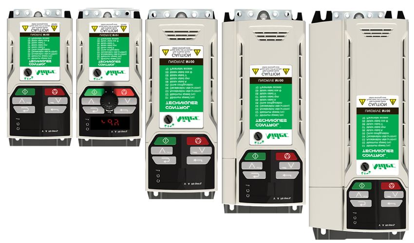
2.5 Keypad and display
The keypad and display provide information to the user regarding the operating status of the drive and trip codes, and provide the means for changing
parameters, stopping and starting the drive, and the ability to perform a drive reset.
Figure 2-2 Unidrive M100 keypad detail Figure 2-3 Unidrive M101 keypad detail
8
V A Hz rpm %
9 V A Hz rpm %
10
11
6 1
1
5 2 7
4 3
(1) The Enter button is used to enter parameter view or edit mode, or to accept a parameter edit.
(2 / 5) The Navigation button can be used to select individual parameters or to edit parameter values.
(3) The Stop / Reset button is used to stop and reset the drive in keypad mode. It can also be used to reset the drive in terminal mode.
(4) The Start button is used to start the drive in keypad mode.
(6) The Escape button is used to exit from the parameter edit / view mode.
(7) The Speed Reference Potentiometer is used to control the speed reference in keypad mode (only on Unidrive M101).
(8) Units.
(9) Run forward indicator.
(10) Run reverse indicator.
(11) Keypad reference indicator.
10 Unidrive M100 / M101 Control User Guide
Issue Number: 3Safety Product Mechanical Electrical Getting Basic Running the Advanced
Optimization NV Media Card Diagnostics UL Listing
information information installation installation started parameters motor parameters
2.6 Nameplate description
Figure 2-4 Typical drive rating labels for size 2
Key to approvals
Model number
CE approval Europe
C Tick approval Australia
M100-022 00042 A
Input USA &
Power rating UL / cUL approval
voltage R
Canada
Refer to
1714 User Guide
RoHS compliant China
Date code
USA &
Functional safety
Canada
EurAsian Conformity EurAsia
Model Input Power
number frequency rating
M100-022 0042 A 1714 Date code
Input voltage No. of phases &
7.5A Typical input current
Output 0-550Hz
voltage
8000001001
Serial Heavy duty
number output current
Patents: www.ctpatents.info
Manuals: www.ctmanuals.info
Output Approvals
frequency
Refer to Figure 2-1 Model number on page 8 for further information relating to the labels.
NOTE
Date code format
The date code is four numbers. The first two numbers indicate the year and the remaining numbers indicate the week of the year in which the drive
was built. This new format started in 2017.
Example:
A date code of 1710 would correspond to week 10 of year 2017.
Unidrive M100 / M101 Control User Guide 11
Issue Number: 3Safety Product Mechanical Electrical Getting Basic Running the Advanced
Optimization NV Media Card Diagnostics UL Listing
information information installation installation started parameters motor parameters
2.7 Options
Figure 2-5 Options available with the drive
1
1. AI-Backup Adaptor
Table 2-1 Adaptor Interface (AI) option module identification
Type Option module Name Further Details
+24 V Backup and SD card interface
AI-Backup adaptor
Provides a +24 V Backup supply input and SD card interface
Backup
+24 V Backup and SD card interface
AI-Smart adaptor Supplied with 4 GB SD card for parameter copying and an input
for 24 V Backup
12 Unidrive M100 / M101 Control User Guide
Issue Number: 3Safety Product Mechanical Electrical Getting Basic Running the Advanced
Optimization NV Media Card Diagnostics UL Listing
information information installation installation started parameters motor parameters
3 Mechanical installation
3.1 Installing / removing option
Figure 3-1 Installing the AI-Backup adaptor
1 2
3
1. Identify the two plastic fingers on the underside of the AI-Backup adaptor (1) - then insert the two fingers into the corresponding slots in the
spring-loaded sliding cover on the top of the drive.
2. Hold the adaptor firmly and push the spring loaded protective cover towards the back of the drive to expose the connector block (2) below.
3. Press the adaptor downwards (3) until the adaptor connector locates into the drive connection below.
Figure 3-2 Removal of the AI-Backup Adaptor
1
• To remove the AI-Backup adaptor, pull it up away from the drive in the direction shown (1)
Unidrive M100 / M101 Control User Guide 13
Issue Number: 3Safety Product Mechanical Electrical Getting Basic Running the Advanced
Optimization NV Media Card Diagnostics UL Listing
information information installation installation started parameters motor parameters
4 Electrical installation 4.2 Control connections
4.2.1 General
4.1 24 Vdc supply Table 4-1 The control connections consist of:
The 24 Vdc supply connected to the +24 V supply terminals on the AI- Terminal
Function Qty Control parameters available
Backup adaptor provides the following functions: number
• It can be used to clone or load parameters in order to pre-configure Single ended analog Mode, offset, invert, scaling,
1 2
drives when the line power supply is not available. The keypad can input destination
be used to setup parameters if required. However, the drive will be in Digital input 3 Destination, invert 11, 12, 13
the Under Voltage state unless the line power supply is enabled, Input / output mode select,
therefore diagnostics may not be possible. (Power down save Digital input / output 1 10
destination / source, invert
parameters are not saved when using the 24 V back-up power
PWM or frequency Source, scaling, maximum
supply input). 1 10
output output frequency, mode
The working voltage range of the 24 V back-up power supply is as Relay 1 Source, invert 41, 42
follows: Drive enable 1 11
0V (connected internally to 0V common - Control +10 V User output 1 4
0V
terminal 1) +24 V User output 1 9
+ 24 V + 24 V Backup supply input 0V common 1 1
Nominal operating voltage 24.0 Vdc Key:
Minimum continuous operating voltage 19.2 V Indicates the parameter which is being controlled
Destination parameter:
Maximum continuous operating voltage 30.0 V by the terminal / function
Minimum start up voltage 12.0 V Indicates the parameter being output by the
Source parameter:
terminal
Minimum power supply requirement at 24 V 20 W
Analog - indicates the mode of operation of the
Maximum power supply continuous current 3A terminal, i.e. voltage 0-10 V, current 4-20 mA etc.
Recommended fuse 1 A, 50 Vdc Mode parameter: Digital - indicates the mode of operation of the
terminal, (the Drive Enable terminal is fixed in
Minimum and maximum voltage values include ripple and noise. Ripple
positive logic).
and noise values must not exceed 5 %.
Figure 4-1 Location of the 24 Vdc power supply connection on the All analog terminal functions can be programmed in menu 7.
AI-Backup adaptor All digital terminal functions (including the relay) can be programmed in
menu 8.
The control circuits are isolated from the power circuits in the
drive by basic insulation (single insulation) only. The installer
must ensure that the external control circuits are insulated
from human contact by at least one layer of insulation
WARNING (supplementary insulation) rated for use at the AC supply
voltage.
If the control circuits are to be connected to other circuits
classified as Safety Extra Low Voltage (SELV) (e.g. to a
personal computer), an additional isolating barrier must be
WARNING
included in order to maintain the SELV classification.
If any of the digital inputs (including the drive enable input)
are connected in parallel with an inductive load (i.e.
contactor or motor brake) then suitable suppression (i.e.
diode or varistor) should be used on the coil of the load. If no
CAUTION suppression is used then over voltage spikes can cause
damage to the digital inputs and outputs on the drive.
NOTE N
NOTE Any signal cables which are carried inside the motor cable (i.e. motor
thermistor, motor brake) will pick up large pulse currents via the cable
The 24 Vdc Backup supply can be used on all frame sizes. capacitance. The shield of these signal cables must be connected to
ground close to the point of exit of the motor cable, to avoid this noise
current spreading through the control system.
14 Unidrive M100 / M101 Control User Guide
Issue Number: 3Safety Product Mechanical Electrical Getting Basic Running the Advanced
Optimization NV Media Card Diagnostics UL Listing
information information installation installation started parameters motor parameters
Figure 4-2 Default terminal functions
1 14 41 42
0V common
1
Analog
frequency 2
reference 1
4
+10 V
+24 V
9
At zero frequency 10
Drive enable 11
Run forward 12
Run reverse 13
41 Relay
Drive OK (over-voltage
42 category II)
4.2.2 Control terminal specification
1 0V common
Function Common connection for all external devices
2 Analog input 1
Default function Frequency reference
Type of input Unipolar single-ended analog voltage or unipolar current
Mode controlled by… Pr 07.007
Operating in voltage mode (default)
Full scale voltage range 0V to +10 V ±3 %
Maximum offset ±30 mV
Absolute maximum voltage range -18 V to +30 V relative to 0V
Input resistance 100 kΩ
Operating in current mode
0 to 20 mA ±5 %, 20 to 0 mA ±5 %,
Current ranges
4 to 20 mA ±5 %, 20 to 4 mA ±5 %
Maximum offset 250 µA
Absolute maximum voltage (reverse bias) -18 V to +30 V relative to 0V
Absolute maximum current 25 mA
Equivalent input resistance 165 Ω
Common to all modes
Resolution 11 bits
Sample rate 4 ms
4 +10 V user output
Default function Supply for external analog devices
Nominal voltage 10.2 V
Voltage tolerance ±3 %
Maximum output current 5 mA
Unidrive M100 / M101 Control User Guide 15
Issue Number: 3Safety Product Mechanical Electrical Getting Basic Running the Advanced
Optimization NV Media Card Diagnostics UL Listing
information information installation installation started parameters motor parameters
9 +24 V user output
Default function Supply for external digital devices
Voltage tolerance ±20 %
Maximum output current 100 mA
Protection Current limit and trip
10 Digital I/O 1
Default function AT ZERO FREQUENCY output
Positive logic digital input, positive logic voltage source output.
Type
PWM or frequency output modes can be selected.
Input / output mode controlled by … Pr 08.031
Operating as in input
Absolute maximum applied voltage range -8 V to +30 V relative to 0V
Impedance 6.8 kΩ
Input threshold 10 V ±0.8 V (IEC 61131-2)
Operating as an output
Nominal maximum output current 50 mA
Maximum output current 100 mA (total including +24 Vout)
Common to all modes
Voltage range 0V to +24 V
Sample rate 1 ms when routed to destinations Pr 06.035 or Pr 06.036, otherwise 4 ms
11 Digital Input 2
12 Digital Input 3
13 Digital Input 4
Terminal 11 default function DRIVE ENABLE input
Terminal 12 default function RUN FORWARD input
Terminal 13 default function RUN REVERSE input
Type Positive logic only digital inputs
Voltage range 0V to +24 V
Absolute maximum applied voltage range -18 V to +30 V relative to 0V
Impedance 6.8 kΩ
Input threshold 10 V ±0.8 V (IEC 61131-2)
Sample rate 1 ms when routed to destinations Pr 06.035 or Pr 06.036, otherwise 4 ms.
41
Relay contacts
42
Default function Drive OK indicator
Contact voltage rating 240 Vac, Installation over-voltage category II
2 A AC 240 V
Contact maximum current rating 4 A DC 30 V resistive load
0.5 A DC 30 V inductive load (L/R = 40 ms)
Contact minimum recommended rating 12 V 100 mA
Contact type Normally open
Default contact condition Closed when power applied and drive OK
Update rate 1 ms
To prevent the risk of a fire hazard in the event of a fault, a fuse or other over-current protection must be installed in the relay circuit.
WARNING
16 Unidrive M100 / M101 Control User Guide
Issue Number: 3Safety Product Mechanical Electrical Getting Basic Running the Advanced
Optimization NV Media Card Diagnostics UL Listing
information information installation installation started parameters motor parameters
5 Getting started The parameter value is correctly displayed on the keypad display as
shown in Table 5-3 below.
This chapter introduces the user interfaces, menu structure and security Table 5-3 Keypad display formats
levels of the drive. Display formats Value
5.1 Understanding the display Standard 100.99
Date 31.12.11 or 12.31.11
5.1.1 Keypad
The keypad display consists of a 6 digit LED display. The display shows Time 12.34.56
the drive status or the menu and parameter number currently being Character ABCDEF
edited. Binary 5
The mm.ppp signifies the menu parameter number of the drive’s menus Version number 01.23.45
and parameter.
The display also includes LED indicators showing units and status as
shown in Figure 5-1. 5.2 Keypad operation
When the drive is powered up, the display will show the power up
parameter defined by Parameter Displayed At Power-Up (11.022). 5.2.1 Control buttons
The keypad consists of:
NOTE
• Up and down button - Used to navigate the parameter structure and
The values in the Status Mode Parameters (Pr 22 and Pr 23) shown on
change parameter values.
the display when the drive is running, can be toggled by using the • Enter button - Used to change between parameter edit and view
escape button.
mode, as well as entering data.
Figure 5-1 Unidrive M100 keypad detail • Escape button - Used to exit from parameter edit or view mode. In
parameter edit mode, if parameter values are edited and the escape
V A Hz rpm % button pressed, the parameter value will be restored to the value it
had on entry to edit mode.
• Start button - Used to provide a 'Run' command if keypad mode is
selected.
• Stop / Reset button - Used to reset the drive. In keypad mode can be
6 1 used for 'Stop'.
5 2
4 3
Table 5-1 Key to Figure 5-1
1: Enter button 4: Start button (green)
2: Up button 5: Down button
3: Stop/Reset button (red) 6: Escape button
Figure 5-2 Unidrive M101 keypad detail
8
9 V A Hz rpm %
10
11
1
7
Table 5-2 Key to Figure 5-2
7: Speed reference potentiometer 10: Run reverse indicator
8: Unit indicators 11: Keypad reference indicator
9: Run forward indicator
NOTE
The red stop button is also used to reset the drive.
On the Unidrive M101, the speed reference potentiometer is used to
adjust the keypad reference.
Unidrive M100 / M101 Control User Guide 17
Issue Number: 3Safety Product Mechanical Electrical Getting Basic Running the Advanced
Optimization NV Media Card Diagnostics UL Listing
information information installation installation started parameters motor parameters
Figure 5-3 Display modes
Status
Mode
To enter Parameter View Mode, To return to Status Mode,
press button press button
0.00 Parameter
View Mode
Pr 10
Press or to select parameter To return to Parameter View Mode,
press button
Pr 01
To view parameter value
press button
Parameter
Value View 0.00
To return to Parameter Value View
press button to keep the new value
press button to ignore new value and
return the parameter to the pre-edited value
To enter Edit Mode,
press button
Holding or increases or decreases value
0.00
Edit Mode (edited digit flashes)
NOTE
The up and down buttons can only be used to move between menus if Pr 10 has been set to show 'ALL'. Refer to section 5.8 Parameter access level
and security on page 21.
18 Unidrive M100 / M101 Control User Guide
Issue Number: 3Safety Product Mechanical Electrical Getting Basic Running the Advanced
Optimization NV Media Card Diagnostics UL Listing
information information installation installation started parameters motor parameters
NOTE 5.3 Menu structure
The up and down buttons can only be used to move between menus if The drive parameter structure consists of menus and parameters.
Pr 10 has been set to show 'ALL'. Refer to section 5.8 Parameter access The drive initially powers up so that only Menu 0 can be viewed. The up
level and security on page 21.
and down arrow buttons are used to navigate between parameters and
Figure 5-4 Mode examples once Pr 10 has been set to 'All' the up and down buttons are used to
navigate between menus.
For further information refer to section 5.8 Parameter access level and
security on page 21.
The menus and parameters rollover in both directions i.e. if the last
parameter is displayed, a further press will cause the display to rollover
and show the first parameter.
When changing between menus, the drive remembers which parameter
was last viewed in a particular menu and thus displays that parameter.
1 2
5.4 Menu 0
Menu 0 is used to bring together various commonly used parameters for
basic easy set up of the drive. The parameters displayed in Menu 0 can
be configured in Menu 22.
Appropriate parameters are copied from the advanced menus into Menu
0 and thus exist in both locations.
For further information, refer to Chapter 6 Basic parameters on page 22.
3 4 Figure 5-5 Menu 0 copying
Menu 2
1 Parameter view mode: Read write or Read only
2 Status mode: Drive OK status
If the drive is ok and the parameters are not being edited or viewed, the 02.021 10.0
display will show one of the following:
Menu 0
inh', 'rdy' or status mode parameter value.
3 Status mode: Trip status Menu 11
04 10.0
When the drive is in trip condition, the display will indicate that the drive 05 AV
has tripped and the display will show the trip code. For further 06 4.1
information regarding trip codes, refer to section 11.4 Trips, Sub-trip 11.034 AV
numbers on page 81.
4 Status mode: Alarm status Menu 5
During an 'alarm' condition the display flashes between the drive status
parameter value and the alarm.
05.007 4.1
Do not change parameter values without careful
consideration; incorrect values may cause damage or a
safety hazard.
WARNING
NOTE
When changing the values of parameters, make a note of the new
values in case they need to be entered again.
NOTE
New parameter values must be saved to ensure that the new values
apply after the drive has been power cycled. Refer to section 5.6 Saving
parameters on page 20.
Unidrive M100 / M101 Control User Guide 19
Issue Number: 3Safety Product Mechanical Electrical Getting Basic Running the Advanced
Optimization NV Media Card Diagnostics UL Listing
information information installation installation started parameters motor parameters
5.5 Advanced menus 5.5.2 Alarm indications
The advanced menus consist of groups or parameters appropriate to a An alarm is an indication given on the display by alternating the alarm
specific function or feature of the drive. Menus 0 to 22 can be viewed on string with the drive status string on the display. Alarms strings are not
the Keypad. displayed when a parameter is being edited.
Table 5-4 Advanced menu descriptions Table 5-6 Alarm indications
Menu Description Alarm string Description
Commonly used basic set up parameters for quick / easy Brake resistor overload. Braking Resistor Thermal
0
programming br.res Accumulator (10.039) in the drive has reached
1 Frequency reference 75.0 % of the value at which the drive will trip.
2 Ramps Motor Protection Accumulator (04.019) in the drive
3 Frequency control OV.Ld has reached 75.0 % of the value at which the drive
4 Torque and current control will trip and the load on the drive is >100 %.
5 Motor control Drive over temperature. Percentage Of Drive
6 Sequencer and clock d.OV.Ld Thermal Trip Level (07.036) in the drive is greater
than 90 %.
7 Analog I/O
The autotune procedure has been initialized and an
8 Digital I/O tuning
autotune in progress.
10 Status and trips
Limit switch active. Indicates that a limit switch is
11 Drive set-up and identification LS
active and that is causing the motor to be stopped.
22 Menu 0 set-up
Lo.AC Low voltage mode. See Low AC Alarm (10.107).
5.5.1 Display messages Current limit active. See Current Limit Active
The following tables indicate the various possible mnemonics which can I.AC.Lt
(10.009).
be displayed by the drive and their meaning. 24 V backup not present. See 24V Alarm Loss
24.LoSt
Table 5-5 Status indications Enable (11.098).
Drive
String Description output
stage
5.6 Saving parameters
The drive is inhibited and cannot be run. When changing a parameter in Menu 0, the new value is saved when
The Drive Enable signal is not applied to
the drive enable terminal or Pr 06.015 is pressing the Enter button to return to parameter view mode
inh Disabled
set to 0. The other conditions that can from parameter edit mode.
prevent the drive from enabling are shown If parameters have been changed in the advanced menus, then the
as bits in Enable Conditions (06.010) change will not be saved automatically. A save function must be carried
The drive is ready to run. The drive enable out.
rdy is active, but the drive inverter is not active Disabled Procedure
because the final drive run is not active 1. Select ‘Save' in Pr 00 or Pr mm.000 (alternatively enter a value of
StoP The drive is stopped / holding zero speed. Enabled 1001 in Pr 00 or Pr mm.000)
S.Loss Supply loss condition has been detected Enabled • Press the red reset button
dc inj The drive is applying dc injection braking Enabled
The drive has tripped and no longer
Er controlling the motor. The trip code Disabled
appears on the display.
The drive is in the under voltage state
5.7 Restoring parameter defaults
UV Disabled Restoring parameter defaults by this method saves the default values in
either in low voltage or high voltage mode.
the drives memory. User security status (Pr 10) and User security code
HEAt The motor pre-heat function is active. Enabled
(Pr 25) are not affected by this procedure).
Procedure
1. Ensure the drive is not enabled, i.e. drive is in inhibit or under
voltage state.
2. Select 'Def.50’ or 'Def.60' in Pr 00 or Pr mm.000. (alternatively, enter
1233 (50 Hz settings) or 1244 (60 Hz settings) in Pr 00 or
Pr mm.000).
• Press the red reset button
20 Unidrive M100 / M101 Control User Guide
Issue Number: 3Safety Product Mechanical Electrical Getting Basic Running the Advanced
Optimization NV Media Card Diagnostics UL Listing
information information installation installation started parameters motor parameters
5.8 Parameter access level and security 5.8.2 Changing the User Security Level /Access
Level
The parameter access level determines whether the user has access to
The security level is determined by the setting of Pr 10 or Pr 11.044. The
Menu 0 only or to all the advanced menus (Menus 1 to 22) in addition to
Security Level can be changed through the keypad even if the User
Menu 0.
Security Code has been set.
The User Security determines whether the access to the user is read
only or read write. 5.8.3 User Security Code
The User Security Code, when set, prevents write access to any of the
Both the User Security and Parameter Access Level can operate
parameters in any menu.
independently of each other as shown in Table 5-7.
Setting User Security Code
Table 5-7 Parameter access level and security
Enter a value between 1 and 9999 in Pr 25 and press the
User button; the security code has now been set to this value. In order to
security Access Advanced menu activate the security, the Security level must be set to desired level in
Menu 0 status
status level status Pr 10. When the drive is reset, the security code will have been activated
(Pr 10) and the drive returns to LEVEL.1. The value of Pr 25 will return to 0 in
order to hide the security code.
0 LEVEL.1 RW Not visible
1 LEVEL.2 RW Not visible Unlocking User Security Code
2 ALL RW RW Select a parameter that need to be edited and press the button,
3 StAtUS RW Not visible the display will now show ‘Co’. Use the arrow buttons to set the security
4 no.Acc RW Not visible code and press the button. With the correct security code
The default settings of the drive are Parameter Access Level LEVEL.1 entered, the display will revert to the parameter selected in edit mode.
and user Security Open i.e. read / write access to Menu 0 with the If an incorrect security code is entered, the following message ‘Co.Err’ is
advanced menus not visible. displayed, and the display will revert to parameter view mode.
5.8.1 User Security Level / Access Level Disabling User Security
The drive provides a number of different levels of security that can be set Unlock the previously set security code as detailed above. Set Pr 25 to 0
by the user via User Security Status (Pr 10); these are shown in the table and press the button. The User Security has now been
below. disabled, and will not have to be unlocked each time the drive is
powered up to allow read / write access to the parameters.
User Security
Status Description
(Pr 10)
5.9 Displaying parameters with non-
LEVEL.1 (0) Access to first 10 parameters in Menu 0 only.
LEVEL.2 (1) Access to all parameters in Menu 0.
default values only
ALL (2) Access to all menus. By selecting 'diff.d' in Pr 00 (Alternatively, enter 12000 in Pr 00), the only
parameters that will be visible to the user will be those containing a non-
The keypad remains in status mode and only first 10
StAtUS (3) default value. This function does not require a drive reset to become
parameters in Menu 0 can be viewed or edited.
active. In order to deactivate this function, return to Pr 00 and select
The keypad remains in status mode and only first 10 'none' (alternatively enter a value of 0). Please note that this function can
parameters in Menu 0 can be viewed or edited. Drive be affected by the access level enabled, refer to section 5.8 Parameter
no.Acc (4)
parameters cannot be accessed via a comms access level and security on page 21 for further information regarding
interface. access level.
5.10 Displaying destination parameters only
By selecting 'dest' in Pr 00 (Alternatively enter 12001 in Pr 00), the only
parameters that will be visible to the user will be destination parameters.
This function does not require a drive reset to become active. In order to
deactivate this function, return to Pr 00 and select 'none' (alternatively
enter a value of 0).
Please note that this function can be affected by the access level
enabled, refer to section 5.8 Parameter access level and security on
page 21 for further information regarding access level.
Unidrive M100 / M101 Control User Guide 21
Issue Number: 3Safety Product Mechanical Electrical Getting Basic Running the Advanced
Optimization NV Media Card Diagnostics UL Listing
information information installation installation started parameters motor parameters
6 Basic parameters
Menu 0 is used to bring together various commonly used parameters for basic easy set up of the drive. All the parameters in Menu 0 appear in other
menus in the drive (denoted by {…}). Menu 22 can be used to configure the parameters in Menu 0.
6.1 Parameter ranges and Variable minimum/maximums:
Some parameters in the drive have a variable range with a variable minimum and a variable maximum value which is dependent on one of the
following:
• The settings of other parameters
• The drive rating
• The drive mode
• Combination of any of the above
For more information please see section 10.1 Parameter ranges and Variable minimum/maximums: on page 45.
6.2 Menu 0: Basic parameters
Range (Ú) Default (Ö)
Parameter Type
OL OL
01 Minimum Speed {01.007} 0.00 to Pr 02 Hz 0.00 Hz RW Num US
50 Hz default: 50.00 Hz
02 Maximum Speed {01.006} 0.00 to 550.00 Hz RW Num US
60 Hz default: 60.00 Hz
03 Acceleration Rate 1 {02.011} 0.0 to 32000.0 s / 100 Hz 5.0 s / 100 Hz RW Num US
04 Deceleration Rate 1 {02.021} 0.0 to 32000.0 s / 100 Hz 10.0 s / 100 Hz RW Num US
AV (0), AI (1), AV.Pr (2), AI.Pr (3),
05 Drive Configuration {11.034} PrESEt (4), PAd (5), PAd.rEF (6), AV (0)* RW Txt PT US
torquE (8)
Maximum Heavy Duty Rating
06 Motor Rated Current {05.007} 0.00 to Drive Rating A RW Num RA US
(11.032) A
50 Hz default:
1500.0 rpm
07 Motor Rated Speed** {05.008} 0.0 to 33000.0 rpm RW Num US
60 Hz default:
1800.0 rpm
110 V drive: 230 V
200 V drive: 230 V
08 Motor Rated Voltage {05.009} 0 to 240 V or 0 to 480 V RW Num RA US
400 V drive 50 Hz: 400 V
400 V drive 60 Hz: 460 V
09 Motor Rated Power Factor*** {05.010} 0.00 to 1.00 0.85 RW Num RA US
LEVEL.1 (0), LEVEL.2 (1), ALL (2), StAtUS (3),
10 User Security Status {11.044} LEVEL.1 (0) RW Num ND PT
no.Acc (4)
11 Start/Stop Logic Select {06.004} 0 to 6 0 RW Num US
15 Jog Reference {01.005} 0.00 to 300.00 Hz 1.50 Hz RW Num US
4-20.S (-6), 20-4.S (-5), 4-20.L (-4), 20-4.L (-3), 4-
16 Analog Input 1 Mode {07.007} 20.H (-2), 20-4.H (-1), 0-20 (0), 20-0 (1), 4-20.tr (2), Volt (6) RW Txt US
20-4.tr (3), 4-20 (4), 20-4 (5), Volt (6)
17 Bipolar Reference Enable {01.010} Off (0) or On (1) Off (0) RW Bit US
18 Preset Reference 1 {01.021} 0.00 to Pr 02 Hz 0.00 Hz RW Num US
19 Preset Reference 2 {01.022} 0.00 to Pr 02 Hz 0.00 Hz RW Num US
20 Preset Reference 3 {01.023} 0.00 to Pr 02 Hz 0.00 Hz RW Num US
21 Preset Reference 4 {01.024} 0.00 to Pr 02 Hz 0.00 Hz RW Num US
22 Status Mode Parameter 2 {11.019} 0.000 to 30.999 4.020 RW Num PT US
23 Status Mode Parameter 1 {11.018} 0.000 to 30.999 2.001 RW Num PT US
24 Customer Defined Scaling {11.021} 0.000 to 10.000 1.000 Rw Num US
25 User Security Code {11.030} 0 to 9999 0 RW Num ND PT US
Power-up Keypad Control
27 {01.051} Reset (0), Last (1), Preset (2) Reset (0) RW Txt US
Mode Reference
28 Ramp Mode Select {02.004} Fast (0), Std (1), Std.bst (2), Fst.bst (3) Std (1) RW Txt US
30 Parameter Cloning {11.042} NonE (0), rEAd (1), Prog (2), Auto (3), boot (4) NonE (0) RW Txt NC US
Coast (0), rp (1), rp.dc I (2), dc I (3),
31 Stop Mode {06.001} rp (1) RW Txt US
td.dc I (4),dis (5)
32 Dynamic V to F Select {05.013} 0 to 1 0 RW Num US
dis (0), Enable (1), Fr.Only (2),
33 Catch A Spinning Motor {06.009} dis (0) RW Txt US
Rv.Only (3)
35 Digital Output 1 Control {08.091} 0 to 21 0 RW US
22 Unidrive M100 / M101 Control User Guide
Issue Number: 3You can also read