Product Manual BB and BBC series - Black Bruin
←
→
Page content transcription
If your browser does not render page correctly, please read the page content below
Product Manual BB and BBC series
Contents

Contents

1    General Instructions......................................................................... 4
     1.1    About the manual............................................................................................................................................4
     1.2    Intended use..................................................................................................................................................... 4
     1.3    Warranty............................................................................................................................................................. 4
     1.4    Product identification..................................................................................................................................... 4
     1.5    Publication date............................................................................................................................................... 5
     1.6    Declaration of incorporation......................................................................................................................... 5

2    Safety Instructions........................................................................... 6
     2.1    Warning symbols..............................................................................................................................................6

3    Motor Description.............................................................................. 7
     3.1    Working principle.............................................................................................................................................. 7
     3.2    Motor model code BB series.........................................................................................................................8
     3.3    Motor model code BBC series...................................................................................................................... 9
     3.4    Technical data BB series.............................................................................................................................. 10
     3.5    Technical data BBC series........................................................................................................................... 12
     3.6    Motor interfaces............................................................................................................................................. 14
            3.6.1       Main dimensions..........................................................................................................................14
            3.6.2       Shaft interfaces........................................................................................................................... 16
            3.6.3       Hub interfaces..............................................................................................................................21
     3.7    Rotating direction..........................................................................................................................................25
     3.8    Freewheeling.................................................................................................................................................. 26
            3.8.1       Hydrostatic freewheeling......................................................................................................... 26
            3.8.2       Mechanical freewheeling.......................................................................................................... 27
     3.9    1-speed motors..............................................................................................................................................28
     3.10   Multi-speed motors...................................................................................................................................... 29
     3.11   Seal protector and grease nipples............................................................................................................. 31
     3.12   Brakes................................................................................................................................................................31
            3.12.1      Static wet multi-disc brake for BBC and BB series motors..............................................31
            3.12.2      Double brake for BBC series motors...................................................................................... 32

4    System Design................................................................................. 33
     4.1    Motor hydraulic circuit................................................................................................................................. 33
            4.1.1     Simple connection......................................................................................................................33
            4.1.2     Counter pressure operation..................................................................................................... 33
            4.1.3     Hydrostatic braking.................................................................................................................... 34
            4.1.4     Short circuit operation...............................................................................................................34
     4.2    Hydraulic connections................................................................................................................................. 35
     4.3    External freewheeling valve........................................................................................................................37
     4.4    Hydraulic fluid................................................................................................................................................ 39
            4.4.1     Motors in parallel or series circuit........................................................................................... 39
            4.4.2     Hydraulic fluid type..................................................................................................................... 41
            4.4.3     Hydraulic fluid properties.......................................................................................................... 41
            4.4.4     Hydraulic fluid cleanliness.........................................................................................................41
     4.5    Operating pressures...................................................................................................................................... 41
            4.5.1     Case pressure...............................................................................................................................41
            4.5.2     Pilot pressure............................................................................................................................... 42
            4.5.3     Working line pressure.................................................................................................................42

2                                                                                                                                                         Product Manual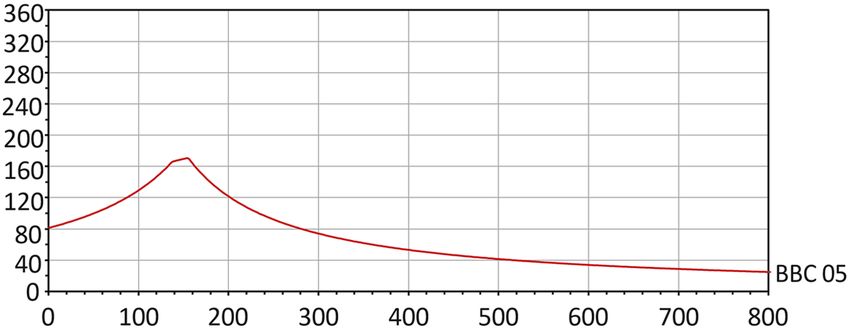
Contents

5     Motor Sizing..................................................................................... 46
      5.1    Load carrying capacity................................................................................................................................ 46
             5.1.1    Wheel offset..................................................................................................................................46
             5.1.2    Allowed wheel load..................................................................................................................... 47
             5.1.3    Service life.................................................................................................................................... 48
      5.2    Performance...................................................................................................................................................50
             5.2.1    Rotating speed and flow rate.................................................................................................. 50
             5.2.2    Torque............................................................................................................................................. 51
             5.2.3    Power............................................................................................................................................. 52
      5.3    Performance charts......................................................................................................................................52
             5.3.1    BB motors performance curves..............................................................................................52
             5.3.2    BBC motors performance curves...........................................................................................58
             5.3.3    BB motors case leakage............................................................................................................62
             5.3.4    BBC motors case leakage.........................................................................................................63

6     Installation Instructions................................................................ 64
      6.1    Conditions of installation and application.............................................................................................. 64
      6.2    Mounting the motor......................................................................................................................................64
      6.3    Flushing the hydraulic system...................................................................................................................64
      6.4    Hydraulic connections................................................................................................................................. 65
      6.5    Air bleeding procedure.................................................................................................................................65
      6.6    Commissioning procedure.......................................................................................................................... 65
      6.7    Tightening torques........................................................................................................................................66

7     Operating Instructions................................................................... 67
      7.1    Break-in period............................................................................................................................................... 67
      7.2    Use.....................................................................................................................................................................67
      7.3    Operating temperature.................................................................................................................................67
      7.4    Demounting the motor.................................................................................................................................67

8     Special Instructions........................................................................69
      8.1    Storing the motor.......................................................................................................................................... 69

Product Manual                                                                                                                                                                      3
General Instructions
1 General Instructions
1.1 About the manual
This manual contains the technical instructions for the Black Bruin BB and BBC series
hydraulic motors. Take these instructions into consideration when planning the use
of the product.
All information given in this manual is current and valid according to the information
available at the time of publication. The manufacturer reserves the rights to
implement changes without prior notice.
Please visit www.blackbruin.com for the most recent version of this manual. The
product datasheets and the 3D-models are available from the manufacturer by
request.
1.2 Intended use
Black Bruin BB and BBC series hydraulic motors are designed to be used as hub
motors on vehicles. They can also be used in other applications that need torque for
rotary movement.
1.3 Warranty
Check the package and the product for transport damage when receiving goods. The
package is not meant for long term storage; protect the product appropriately.
Do not dismantle the product. The warranty is void if the product has been
disassembled.
The manufacturer is not responsible for damages resulting from misinterpreted, non-
compliance, incorrect, or improper use of the product that goes against the
instructions given in this document.
1.4 Product identification
The product identification data can be found on the identification plate attached to
the motor.
1. Serial number
2. Part number
3. Model
4. Maximum allowed operating pressure
Figure 1. Identification plate of the motor.
Note:
The serial number is also stamped on the motor. All manufacturing data
can be found with the serial number.
4 Product ManualGeneral Instructions
1.5 Publication date
17.03.2021 - This manual is published.
1.6 Declaration of incorporation
Product Manual 5Safety Instructions
2 Safety Instructions
The following instructions apply to all procedures associated with the motor. Read
these instructions carefully and follow them closely.
• Use necessary personal protective equipment when working with the motor.
• Support the motor properly. Make sure the motor cannot fall over or turn around
by accident.
• Use only appropriate equipment and attachments for lifting and transferring the
motor.
• Do not use magnetic lifting devices.
• Always use the lifting equipment properly and check the load-bearing capacity.
• Prevent unintended use of the motor during installation and maintenance
procedures by preventing pressurization of the hydraulic lines.
• The operating temperature of the motor may be over 60 ºC (140 °F), which is hot
enough to cause severe burns. Beware of hot hydraulic fluid when disconnecting
the hydraulic connections.
2.1 Warning symbols
The following symbols are used in this manual:
Note:
Useful information.
Danger:
Danger of death or injury.
Attention:
May cause damage to the product.
6 Product ManualMotor Description
3 Motor Description
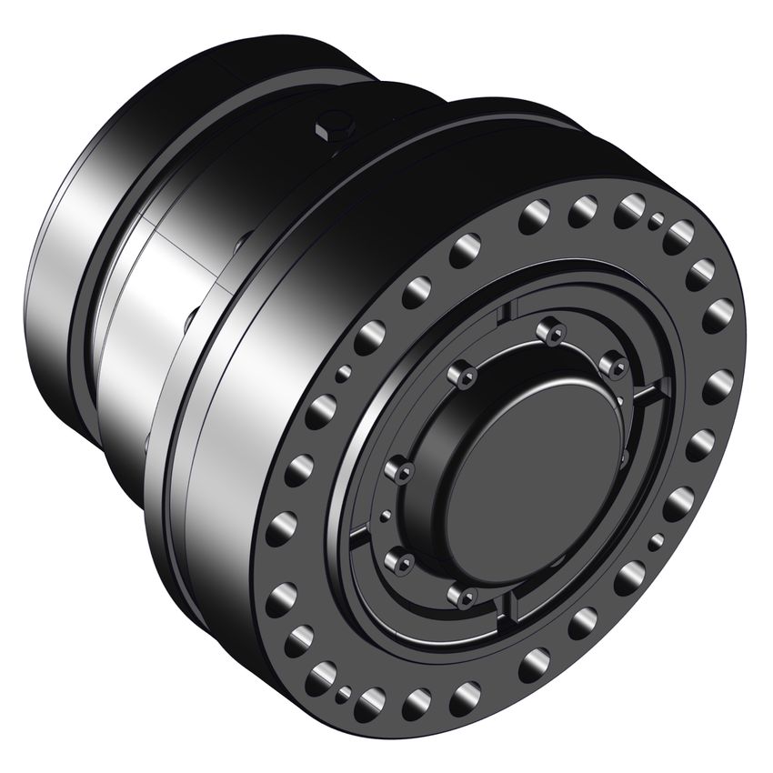
3.1 Working principle
BB and BBC series motors are rotary-housing. This means the motor shaft and the
cylinder block remain in place while the motor is running.
1. Shaft
2. Distribution valve
3. Cylinder block
4. Piston
5. Cam roll
6. Cam ring
7. Bearings
8. Housing
9. Hub
10. Shaft sealing
Figure 2. The main components of the motor.
The rotation of the motor is achieved by feeding pressurized hydraulic fluid through
the motor shaft to the distribution valve. The distribution valve directs the flow to the
pistons which are on a power stroke. Pressure pushes the pistons and cam rolls
outwards against the cam ring on the housing. The waveform of the cam ring
transforms the force into torque. When the pistons reach the end of the power stroke,
the distribution valve closes the flow to the pistons and switches the pistons to a
return stroke.The cam ring pushes the pistons back into the cylinder block preparing
them for the next outward power stroke.
Figure 4. Cylinder block, cam ring and pis-
Figure 3. Flow to the pistons. tons.
Product Manual 7Motor Description
3.2 Motor model code BB series
BB SERIES MODEL CODE 40DVVVYW40
Hydraulic motors with parking brake
40 40DVVVYW40
BB series standard code
D: Motor frame size 40DVVVYW40 BB 4 BB 5 BB 6 BB 7
BB 4: 630-800 ccm 4 ●
BB 5: 1000-1600 ccm 5 ●
BB 6: 2000-3150 ccm 6 ●
BB 7: 4000-6300 ccm 7 ●
VVV: Motor displacement 40DVVVYW40 BB 4 BB 5 BB 6 BB 7
063 : 630 ccm/rev ●
BB 4 displacements
080 : 800 ccm/rev ●
100 : 1000 ccm/rev ●
BB 5 displacements 125 : 1250 cmm/rev ●
160 : 1600 ccm/rev ●
200 : 2000 ccm/rev ●
BB 6 displacements 250 : 2500 ccm/rev ●
315 : 3150 ccm/rev ●
400 : 4000 ccm/rev ●
BB 7 displacements 500 : 5000 ccm/rev ●
630 : 6300 ccm/rev ●
Y: Freewheeling 40DVVVYW40 BB 4 BB 5 BB 6 BB 7
Hydraulic freewheeling 1 ● ● ● ●
Mechanical freewheeling 2 ● ● ● ●
W: Multi-speed option 40DVVVYW40 BB 4 BB 5 BB 6 BB 7
Fixed displacement 1 ● ● ● ●
2-speed 2 : CW rotation ● ● ● ●
2-speed 3 : CCW rotation ● ● ● ●
Code example 4051602140
40DVVVYW40
40 = The motor model series is "BB"
D= The frame of the motor is "BB 5"
VVV = The displacement of the motor is 1600 ccm
Y= The motor with mechanical freewheeling
W= The motor with fixed displacement
8 Product ManualMotor Description
Code example 4051602140
4= The motor with a wet multi-disc parking brake
0= The motor is a standard motor
3.3 Motor model code BBC series
BBC SERIES MODEL CODE CDVWE1Y0AA
Hydraulic motors
C CDVWE1Y0AA
BBC series standard code
D: Motor frame size CDVWE1Y0AA BBC 02 BBC 03 BBC 05
BBC 02: 705-1018 ccm 2 ●
BBC 03: 909-1313 ccm 3 ●
BBC 05: 1572-2271 ccm 5 ●
V: Motor displacement CDVWE1Y0AA BBC 02 BBC 03 BBC 05
1 : 705 ccm/rev ●
BBC 02 displacements 3 : 862 ccm/rev ●
5 : 1018 ccm/rev ●
1 : 909 ccm/rev ●
BBC 03 displacements 3 : 1111 ccm/rev ●
5 : 1313 ccm/rev ●
1 : 1572 ccm/rev ●
BBC 05 displacements 3 : 1922 ccm/rev ●
5 : 2271 ccm/rev ●
W: Multi-speed option CDVWE1Y0AA BBC 02 BBC 03 BBC 05
1-speed 1 : Fixed displacement ● ● ●
2-speed 2 : 100 / 50% displacement ● ● ●
7 : 100 / 75 / 50 / 25 % dis-
4-speed ●
placement
E: Brake option CDVWE1Y0AA BBC 02 BBC 03 BBC 05
Without brake 0 ● ● ●
Static wet multi-disc brake 1 ● ● ●
Dynamic brake + static wet mul- C
● ●
ti-disc parking brake
Y: Freewheeling CDVWE1Y0AA BBC 02 BBC 03 BBC 05
Hydraulic freewheeling 0 ● ● ●
Mechanical freewheeling 1 ● ● ●
Product Manual 9Motor Description
Code example C2321110AA
CDVWE1Y0AA
C= The motor model series is "BBC"
D= The frame of the motor is "BBC 02"
V= The displacement of the motor is 862 ccm
W= The motor with a 2-speed valve (862 ccm - 1/1 displ., 431 ccm - 1/2 displ.)
E= The motor with a wet multi-disc parking brake
1= The motor with a case flushing line
Y= The motor with mechanical freewheeling
0= N/A
AA = The motor is a standard motor
3.4 Technical data BB series
TECHNICAL DATA BB 4 BB 5
Displacement [ccm] 630 800 1000 1250 1600
Maximum torque [Nm]
peak torque 3300 4190 5240 6540 8380
intermittent 2825 3590 4490 5610 7180
Max. operating power [kW]
at full displacement 35 50
at half displacement 21 30
Max. rotating speed [rpm]
at full displacement 240 185 200 160 125
at half displacement 360 275 300 240 185
at freewheeling 600 500
Min. rotating speed [rpm] 2 2
Max. working pressure [bar]
peak pressure 350 350
intermittent 1) 300 300
Max. case pressure [bar]
average 2 2
intermittent 1) 10 10
Pilot pressure for internal valve [bar]
valve released 0-2 0-2
valve engaged 15-30 2) 15-30 2)
Max. flow rate [l/min]
at full displacement 150 200
at half displacement 113 150
Spring operated wet multi-disc brake
(parking brake)
brake torque (min.) [Nm]
3) 3700 8000
10 Product ManualMotor Description
TECHNICAL DATA BB 4 BB 5
releasing pressure [bar] 70 86
brake pressure (max.)
300 300
[bar]
needed oil volume [ccm] 30 40
Weight [kg] 66 114
TECHNICAL DATA BB 6 BB 7
Displacement [ccm] 2000 2500 3150 4000 5000 6300
Maximum torque [Nm]
peak torque 13440 16810 21170 26890 33530 42300
intermittent 11950 14940 18820 23900 29800 37600
Max. operating power [kW]
at full displacement 90 130
at half displacement 54 80
Max. rotating speed [rpm]
at full displacement 175 140 110 125 100 80
at half displacement 220 180 145 160 130 105
at freewheeling 400 350
Min. rotating speed [rpm] 2 2
Max. working pressure [bar]
peak pressure 450 450
intermittent 1) 400 400
Max. case pressure [bar]
average 2 2
intermittent 1) 10 10
Pilot pressure for internal valve [bar]
valve released 0-2 0-2
valve engaged 15-30 2) 15-30 2)
Max. flow rate [l/min]
at full displacement 350 500
at half displacement 225 325
Spring operated wet multi-disc brake
(parking brake)
brake torque (min.) [Nm]
3) 20000 40000
releasing pressure [bar] 52 63
brake pressure (max.)
250 250
[bar]
needed oil volume [ccm] 110 140
Weight [kg] 189 365
1) Intermittent operation: permissible values for maximum of 10% of every minute.
2) If pilot pressure over 30 bar is used, the pilot line should be throttled.
Product Manual 11Motor Description
3) Brake torque for new brake.
3.5 Technical data BBC series
TECHNICAL DATA BBC 02 BBC 03
Displacement [ccm] 705 862 1018 909 1111 1313
Maximum torque [Nm]
peak torque 4645 5680 5965 5990 7320 7690
intermittent 4130 5050 5220 5325 6510 6730
Max. operating power [kW]
at full displacement 42 50
at half displacement 28 33
Max. rotating speed [rpm]
at full displacement 223 182 154 206 169 143
at half displacement 318 260 220 290 238 201
at freewheeling 450 425
Min. rotating speed [rpm] 2 2
Max. working pressure [bar]
peak pressure 450 450 400 450 450 400
intermittent 1) 400 400 350 400 400 350
Max. case pressure [bar]
average 2 2
intermittent 1) 10 10
Pilot pressure for internal valve [bar]
valve released 0-2 0-2
valve engaged 15-30 2) 15-30 2)
Max. flow rate [l/min]
at full displacement 157 187
at half displacement 112 132
Spring operated wet multi-disc brake
(parking brake)
brake torque (min.) [Nm]
3) 6560 8470
releasing pressure [bar] 16 16
brake pressure (max.)
30 30
[bar]
needed oil volume [ccm] 120 150
Dynamic multi-disc brake (service brake)
brake torque (min.) [Nm]
3) 7800 10700
brake pressure (max.)
60 60
[bar]
Weight [kg]
without brake 62 80
12 Product ManualMotor Description
TECHNICAL DATA BBC 02 BBC 03
with parking brake 72 96
with double brake 122 148
TECHNICAL DATA BBC 05
Displacement [ccm] 1572 1922 2271
Maximum torque [Nm]
peak torque 10360 12670 13305
intermittent 9210 11260 11640
Max. operating power [kW]
at full displacement 72
at 3/4 displacement 60
at half displacement 48
at 1/4 displacement 32
Max. rotating speed [rpm]
at full displacement 172 141 119
at 3/4 displacement 205 168 142
at half displacement 244 200 169
at 1/4 displacement 326 266 226
at freewheeling 400
Min. rotating speed [rpm] 2
Max. working pressure [bar]
peak pressure 450 450 400
intermittent 1) 400 400 350
Max. case pressure [bar]
average 2
intermittent 1) 10
Pilot pressure for internal valve [bar]
valve released 0-2
valve engaged 15-30 2)
Max. flow rate [l/min]
at full displacement 270
at 3/4 disp 242
at half displacement 192
at 1/4 disp 128
Spring operated wet multi-disc brake
(parking brake)
brake torque (min.) [Nm]
3) 20600
releasing pressure [bar] 16
brake pressure (max.)
30
[bar]
needed oil volume [ccm] 260
Product Manual 13Motor Description
TECHNICAL DATA BBC 05
Weight [kg]
without brake 138
with parking brake 158
1)Intermittent operation: permissible values for maximum of 10% of every minute.
2) If pilot pressure over 30 bar is used, the pilot line should be throttled.
3) Brake torque for new brake.
3.6 Motor interfaces
3.6.1 Main dimensions
BB series motors with static multi-disc brake
L1
L2
ØD1
Figure 5. Main dimensions of the motor.
MAIN DIMENSIONS BB 4 BB 5 BB 6 BB 7
Motor
L1 [mm] 420 469 480 550
L2 [mm] 265 282 320 382
D1 [mm] 278 342 408 512
14 Product ManualMotor Description
BBC series motors without brake
L1
L2
ØD1
Figure 6. Main dimensions of the motor.
MAIN DIMENSIONS BBC 02 BBC 03 BBC 05
Motor
L1 [mm] 254 268 298
L2 [mm] 233 241 259
D1 [mm] 282 315 376
BBC series motors with static multi-disc brake
L1
L2
ØD1
Figure 7. Main dimensions of the motor.
Product Manual 15Motor Description
MAIN DIMENSIONS BBC 02 BBC 03 BBC 05
Motor
L1 [mm] 322 331 383
L2 [mm] 236 241 263
D1 [mm] 282 315 376
BBC series motors with double brake
L1
L2
ØD1
Figure 8. Main dimensions of the motor.
MAIN DIMENSIONS BBC 02 BBC 03
Motor
L1 [mm] 353 364
L2 [mm] 267 274
D1 [mm] 360 360
3.6.2 Shaft interfaces
The motor is attached to the body of the vehicle or device from the shaft flange. The
hydraulic connections of the motor are located on the plane surface of the shaft
flange.
16 Product ManualMotor Description
BB series motors with static multi-disc brake
C1
R1
ØD3
ØD2
ØD1
Figure 9. Dimensions of the shaft interface.
INTERFACE DIMENSIONS BB 4 BB 5 BB 6 BB 7
Shaft interface
D1 [mm] 140 175 200 260
pattern 6x60° 8x45° 12x30° 16x22,5°
size M16x2,0 M16x2,0 M20x1,5 M20x1,5
strength class
1) 12,9 12,9 12,9 12,9
tightening tor-
330 330 650 650
que 2) [Nm]
D2 min. 3) [mm] 114 150 170 220
D3 min. 4) [mm] 165 200 240 300
R1 max. [mm] 1 1 1 1
C1 [mm] 4-10 4-10 4-10 4-10
1) Strength class as in ISO898-1. If using lower strength class, check interface load
capacity and tightening torque.
2) Declared values are for reference only. Always use application specific
tightening torques when given.
3) Free space for hydraulic connections.
4) Recommended feature to support and center the motor.
Product Manual 17Motor Description
BBC series motors without brake
C1
R1
ØD3
ØD2
ØD1
Figure 10. Dimensions of the shaft interface.
INTERFACE DIMENSIONS BBC 02 BBC 03 BBC 05
Shaft interface
D1 [mm] 160 175 200
pattern 8x45° 10x36° 12x30°
size M16x2,0 M16x2,0 M20x1,5
strength class
1) 12,9 12,9 12,9
tightening tor-
330 330 650
que 2) [Nm]
D2 min. 3) [mm] 135 150 166
D3 min. 4) [mm] 200 216 240
R1 max. [mm] 1 1 1
C1 [mm] 4-10 4-10 4-10
1) Strength class as in ISO898-1. If using lower strength class, check interface load
capacity and tightening torque.
2) Declared values are for reference only. Always use application specific
tightening torques when given.
3) Free space for hydraulic connections.
4) Recommended feature to support and center the motor.
18 Product ManualMotor Description
BBC series motors with static multi-disc brake
C1
R1
ØD3
ØD2
ØD1
Figure 11. Dimensions of the shaft interface.
INTERFACE DIMENSIONS BBC 02 BBC 03 BBC 05
Shaft interface
D1 [mm] 160 175 200
pattern 8x45° 10x36° 12x30°
size M16x2,0 M16x2,0 M20x1,5
strength class
1) 12,9 12,9 12,9
tightening tor-
330 330 650
que 2) [Nm]
D2 min. 3) [mm] 135 150 166
D3 min. 4) [mm] 200 216 240
R1 max. [mm] 1 1 1
C1 [mm] 4-10 4-10 4-10
1) Strength class as in ISO898-1. If using lower strength class, check interface load
capacity and tightening torque.
2) Declared values are for reference only. Always use application specific
tightening torques when given.
3) Free space for hydraulic connections.
4) Recommended feature to support and center the motor.
Product Manual 19Motor Description
BBC series motors with double brake
C1
R1
ØD3
ØD2
ØD1
Figure 12. Dimensions of the shaft interface.
INTERFACE DIMENSIONS BBC 02 BBC 03
Shaft interface
D1 [mm] 160 175
pattern 8x45° 10x36°
size M16x2,0 M16x2,0
strength class
1) 12,9 12,9
tightening tor-
330 330
que 2) [Nm]
D2 min. 3) [mm] 135 150
D3 min. 4) [mm] 200 216
R1 max. [mm] 1 1
C1 [mm] 4-10 4-10
1) Strength class as in ISO898-1. If using lower strength class, check interface load
capacity and tightening torque.
2) Declared values are for reference only. Always use application specific
tightening torques when given.
3) Free space for hydraulic connections.
4) Recommended feature to support and center the motor.
20 Product ManualMotor Description
3.6.3 Hub interfaces
Note:
The attachment screws are not included in the motor delivery. Ensure
correct dimensioning and availability of the hub screws.
There are multiple different type of fastening screws for hub interface.
Select the hub screws according to the wheel rim design.
Figure 13. Hub fastening screw variants.
BB series motors with static multi-disc brake
ØD3
ØD2
ØD1
V1
Figure 14. Dimensions of the hub interface.
Product Manual 21Motor Description
INTERFACE DIMENSIONS BB 4 BB 5 BB 6 BB 7
Hub interface
D1 [mm] 205 275 335 425
pattern 6x60° 8x45° 10x36° 12x30°
size M18x1,5 M20x1,5 M22x1,5 M22x1,5
strength class
1) 10,9 10,9 10,9 10,9
tightening tor-
383 540 728 728
que 2) [Nm]
D2 min. [mm] 161 221 281 371
V1 min. [mm] 1x45° 1x45° 1x45° 1x45°
D3 min. [mm] 278 342 408 512
1) Strength class as in ISO898-1. If using lower strength class, check interface load
capacity and tightening torque.
2) Declared values are for reference only. Always use application specific
tightening torques when given.
The wheel rim or the rotatable device is attached to the motor hub.
BBC series motors without brake
ØD3
ØD2
ØD1
V1
Figure 15. Dimensions of the hub interface.
22 Product ManualMotor Description
INTERFACE DIMENSIONS BBC 02 BBC 03 BBC 05
Hub interface
D1 [mm] 225 275 335
pattern 5x72° 8x45° 10x36°
size M22x1,5 M20x1,5 M22x1,5
strength class
1) 10,9 10,9 10,9
tightening tor-
728 540 728
que 2) [Nm]
D2 min. [mm] 176 221 281
V1 min. [mm] 1x45° 1x45° 1x45°
D3 min. [mm] 282 315 376
1) Strength class as in ISO898-1. If using lower strength class, check interface load
capacity and tightening torque.
2) Declared values are for reference only. Always use application specific
tightening torques when given.
The wheel rim or the rotatable device is attached to the motor hub.
BBC series motors with static multi-disc brake
ØD3
ØD2
ØD1
V1
Figure 16. Dimensions of the hub interface.
Product Manual 23Motor Description
INTERFACE DIMENSIONS BBC 02 BBC 03 BBC 05
Hub interface
D1 [mm] 225 275 335
pattern 5x72° 8x45° 10x36°
size M22x1,5 M20x1,5 M22x1,5
strength class
1) 10,9 10,9 10,9
tightening tor-
728 540 728
que 2) [Nm]
D2 min. [mm] 176 221 281
V1 min. [mm] 1x45° 1x45° 1x45°
D3 min. [mm] 282 315 376
1) Strength class as in ISO898-1. If using lower strength class, check interface load
capacity and tightening torque.
2) Declared values are for reference only. Always use application specific
tightening torques when given.
The wheel rim or the rotatable device is attached to the motor hub.
BBC series motors with double brake
ØD3
ØD2
ØD1
V1
Figure 17. Dimensions of the hub interface.
24 Product ManualMotor Description
INTERFACE DIMENSIONS BBC 02 BBC 03
Hub interface
D1 [mm] 225 275
pattern 5x72° 8x45°
size M22x1,5 M20x1,5
strength class
1) 10,9 10,9
tightening tor-
728 540
que 2) [Nm]
D2 min. [mm] 176 221
V1 min. [mm] 1x45° 1x45°
D3 min. [mm] 282 315
1) Strength class as in ISO898-1. If using lower strength class, check interface load
capacity and tightening torque.
2) Declared values are for reference only. Always use application specific
tightening torques when given.
The wheel rim or the rotatable device is attached to the motor hub.
3.7 Rotating direction
Figure 18. Rotating direction of the motor.
The rotating direction of the motor is defined as the rotating direction of the housing
viewed from the hub to the shaft.
The rotating direction of the BB motor and the flow direction in the working lines is
given in the table below.
Table 1: Rotating direction and flow direction of BB motors.
ROTATING DIRECTION flow direction
A→B B→A
40DVVVY140 CW CCW
40DVVVY240 CW CCW
40DVVVY340 CCW CW
Product Manual 25Motor Description
Preferred operating direction of BB motors
The preferred operating direction applies to BB motors with 2-speed valve.
The preferred operating direction is the rotating direction of the motor when the flow
direction is from port A to B.
• 2 = CW motor (For the right side of a vehicle.)
• 3 = CCW motor (For the left side of a vehicle.)
The rotating direction of the BBC motor and the flow direction in the working lines is
given in the table below.
Table 2: Rotating direction and flow direction of BBC motors.
ROTATING DIRECTION flow direction
A→B B→A
No preferred rotating
CW CCW
direction
3.8 Freewheeling
Hydrostatic freewheeling and mechanical freewheeling are options for BB and BBC
series motors.
Black Bruin motors can be freewheeled without energy loss or overheating problems
(stationary cylinder block - no centrifugal forces), even at high speeds. The motors
can be re-engaged or disengaged during movement.
3.8.1 Hydrostatic freewheeling
Hydrostatic freewheeling requires a drain line check valve with 0.5 bar (8 psi) opening
pressure and active feed between the check valve and the drain port of the motor.
A check valve in the drain line regulates the pressure in the case. To limit the pressure
spikes in the case, the drain line and its check valve have to be sized to correspond
with the maximum flow rate at the time of engagement.
In order to create the freewheeling pressure into the case, fluid must be supplied to
case drain line C (all BB motors without flush port C1) between the motor and the
check valve.
Hydrostatic freewheeling of a multispeed BBC motor
In a multispeed (2- and 4-speed) BBC motor without freewheeling springs, the
freewheeling pressure is supplied to the motor case through case flushing line C1.
Multispeed BBC motor has an in-built check valve and thus no external check valve in
case drain line is required.
The freewheeling valve should be positioned as close to the motor as possible to
ensure smooth and rapid mode change.
26 Product ManualMotor Description
3.8.2 Mechanical freewheeling
Figure 19. A piston with the freewheeling
spring.
The motors can be equipped with mechanical freewheeling springs, which enable the
motor disengagement. When there is no pressure in the working lines of the motor,
the springs push the pistons down into the cylinders and hold them there. When
disengaged the motor may be used without active fluid supply from the hydraulic
system.
In systems using mechanical freewheeling, the drain line should be connected
directly to the reservoir to ensure the lowest possible case pressure.
To ensure there is no pressure differential between the work lines A and B (acting
under the pistons) and case drain line C (over the pistons), the three (3) lines are to be
connected together in freewheel mode.
The external freewheeling valve should be positioned as close to the motor as
possible to ensure smooth and rapid mode change.
USING THE FREEWHEELING
When the motor is depressurized and not rotating, the motor will disengage
automatically. The motor disengagement during motion is done with a freewheeling
valve.
The freewheeling valve can be a separate external valve, which connects the working
lines (A and B) and the case drain line (C) together. The purpose of the valve is to
remove pressure difference over the motor pistons. This allows the pistons to retract
with aid of mechanical springs.
• DISENGAGING THE MOTOR
Open the freewheeling valve and depressurize the motor with the directional
control valve to disengage the motor.
• ENGAGING THE MOTOR
Close the freewheeling valve and pressurize the motor with the directional control
valve to engage the motor.
The directional control valve and the freewheeling valve are usually activated
simultaneously.
Attention:
Any pressure in the working lines (A and B) during the freewheeling
pushes the pistons out of the freewheeling position. This causes clattering
noise when the pistons connect to the cam ring.
Product Manual 27Motor Description
Constant clattering of the pistons may cause premature wear or failure of
the motor.
Note:
Another use of the freewheeling is a more extensive speed range for
vehicles having several hydraulic motors. Hydraulic system capacity may
be divided between fewer motors, when some of the motors are
disengaged.
ROTATING SPEED
The rotating speed of the motor should be taken into account when implementing
freewheeling.
• FREEWHEELING SPEED
The freewheeling speed is the highest permissible rotating speed of the motor
during freewheeling.
The permissible freewheeling speeds can be found on the technical data (see
Technical data BB series on page 10 and Technical data BBC series on page 12).
DISENGAGING DELAY
While the pistons are retracting, there is a momentary flow of hydraulic fluid from the
working lines to the casing of the motor. This causes always a small delay when
disengaging the motor. Normal delay is about 1 - 2 seconds.
To minimize the disengaging delay, the hydraulic fluid should have as open channel
as possible:
• The external freewheeling valve should be positioned as close to the motor as
possible.
• All components and lines, which connect the working lines to the case drain line,
should be sized for highest feasible flow rate.
Attention:
Without a freewheeling valve, the delay is considerably longer as the fluid
must seep through the motor. Disengaging the motor during motion
without a freewheeling valve may cause premature wear or failure of the
motor.
3.9 1-speed motors
BB motors BBC motors
40DVVVY140 CDV1E1Y0AA
Displacement control selection 1-speed means the motor has a fixed displacement.
These motors are known as 1-speed motors and are always in full displacement
during operation.
28 Product ManualMotor Description
Figure 20. 1-speed motor. Figure 21. Hydraulic circuit, 1-speed motor.
3.10 Multi-speed motors
BB motors BBC motors
40DVVVY240 CDV2E1Y0AA
40DVVVY340 C5V7E1Y0AA
2-speed BB motors have preferred rotational direction at partial displacement.
Operating the BB motor at partial displacement for an extended time in the non-
preferred direction will lead into motor failure.
2- and 4-speed BBC motors do not have preferred rotational direction and can be
operated at maximum rated power in both directions.
In 2-speed BB and standard 2-speed BBC motors, a 15-30 bar control pressure to Y
port is required to activate 2-speed (partial displacement of a 2-speed motor).
Depressurizing the Y port will return the motor to full displacement. Do not use work/
high pressure in Y port to control a standard 2-speed BB or BBC motor.
BBC 05 4-speed motors have high pressure shift ports (Y1 and Y2). To shift such
motor, the highest available system pressure has to be applied to the shift port.
Typically this highest system pressure is taken from motor work lines A and B by a
shuttle valve.
Product Manual 29Motor Description
C1 C2
A Y B
C2 A Y B C1
P
Figure 22. 2-speed BB motor. Figure 23. 2-speed BBC motor.
Attention:
Always use C2 port to connect the drain line of a multi-speed BBC motor.
C1 can only be used for flush oil or to install an accumulator into the
motor.
Attention:
Take the following things into consideration, when changing the speed
range during motion.
• Hydraulic system supply must adjust to the rapid change of flowrate.
• The rapid change in flow rate may cause momentary jerk. This may be
avoided by throttling the working lines lightly.
• Prevent operating conditions, in which the permissible performance
values could be exceeded.
The permissible performance values are in the technical data (see
Technical data BB series on page 10 and Technical data BBC series on
page 12).
Attention:
Continuous use of high working pressure in the working line B at half
displacement in BB 2-speed motors, may cause premature wear or failure
of the motor.
Note:
Depressurize the 2-speed spool pilot Y to case drain line to prevent
unwanted spool movement.
30 Product ManualMotor Description
3.11 Seal protector and grease nipples
The seal protector is a standard feature in the BBC series motors (excluding the
double brake motors). The seal protector is also known as a grease ring.
The seal protector prevents dirt and moisture from entering to the motor shaft seal.
The operation of the seal protector is based on a sealing lubricant pocket.
Figure 24. BBC motor's seal protector and grease nipples.
3.12 Brakes
There is a variety of brakes available for Black Bruin motors. Brakes, like motors, are
designed in compact, powerful packages and tailored to meet the customer specific
requirements in various applications.
3.12.1 Static wet multi-disc brake for BBC and BB series motors
The spring applied, pressure to release, wet multi-disc brake is a parking brake, but it
can be used dynamically as an emergency brake.
For the minimum brake release pressure, refer to Technical data BB series on page 10
and Technical data BBC series on page 12. The brake operating pressure in BBC (low
pressure brake) can not be higher than 30 bar. Depending on the Black Bruin frame
size, the brake may have internal leakage (max. 0.6 l/min with oil viscosity of 35 cSt),
which has to be considered in the brake circuit design. In BBC motors the brake can
be manually released for emergency towing.
Standard, high pressure, BB brakes are equipped with static seals and do not have
internal leakage. Note that EP, HD and some anti-wear additives in oil can cause
remarkable reduction in brake torque.
Product Manual 31Motor Description
Figure 25. Static wet multi-disc brake
3.12.2 Double brake for BBC series motors
The double brake motor includes:
• A static wet multi-disc low pressure brake
• Spring applied, pressure to release, parking brake
• A dynamic multi-disc brake
• Pressure applied, spring release, service brake
• The ultimate brake for the most demanding conditions
• Cooling through flushing for dynamic use
• Well-sealed structure isolating the brake from the environment and the motor
from the brake
Figure 26. BBC motor's double brake
32 Product ManualSystem Design
4 System Design
4.1 Motor hydraulic circuit
4.1.1 Simple connection
Figure 27. A simple motor hydraulic circuit in an open loop hydraulic system.
In an open loop hydraulic system the hydraulic circuit of the motor is usually
implemented roughly as in the figure above.
• Select the operating direction with the directional control valve (1) by applying the
working pressure (P) to the other working line (A or B).
• The minimum pressure (see Working line pressure on page 42) required in the
return line (T) is created with the cracking pressure of the check valve (2).
• The case drain line port (C) is connected to the system reservoir (T0) as directly as
possible.
Attention:
The case drain line of the motor must always be connected to a reservoir,
even during freewheeling. The case pressure of the motor may rise
significantly, if the motor is completely plugged during use.
Note:
Using the motor on a closed loop hydraulic system is different from the
open loop system. The closed loop system is more complex, but enables
more functions, such as hydrostatic braking, series connection and
counter pressure operation.
4.1.2 Counter pressure operation
Counter pressure operation is needed mainly in series connection (see Motors in
parallel or series circuit on page 39). Counter pressure operation means using the
motor with high back pressure in the return line.
The counter pressure operation affects the torque output of the motor due to
decreased pressure difference over the working lines.
Attention:
Make sure the combined pressure in the working lines does not exceed the
permissible values of the working pressure during counter pressure
operation.
Product Manual 33System Design
Counter pressure operation is not recommended, because high back
pressure stresses the motor more than usual operation.
4.1.3 Hydrostatic braking
Hydrostatic braking means using the output torque of the motor to decelerate the
speed. The output torque is generated by closing the return line of the motor, in
which case a working pressure will form in the return line. The minimum pressure and
feed flow must be maintained in the feed line of the motor during hydrostatic braking.
Note:
The hydrostatic braking requires an active hydraulic fluid supply.
Danger:
Do not use the hydrostatic braking without relief valves in the working
lines. When an external load is rotating the motor, the hydraulic pressure
may increase indefinitely. This leads to danger if a hydraulic hose or
component brakes under high pressure.
4.1.4 Short circuit operation
Short circuit operation means connecting the return flow of the motor directly to the
feed line of the motor.
Short circuit operation is needed, if the motor must be rotated faster than the
hydraulic system can supply and freewheeling the motor is not possible (see
Mechanical freewheeling on page 27).
Make sure the minimum pressure is maintained in both working lines of the motor
during short circuit operation.
Note:
The short circuit operation requires an active hydraulic fluid supply.
Attention:
Make sure the motor does not overheat during short circuit operation.
34 Product ManualSystem Design
4.2 Hydraulic connections
Figure 28. The interface of the motor Figure 29. The interface of the motor
hydraulics without a brake. hydraulics with the double brake.
C2 C
Y Y
A+B A+B
C1 D
Figure 30. The hydraulic connections of a Figure 31. The hydraulic connections of a
2-speed BBC motor without a brake. 2-speed BB motor with a brake.
Product Manual 35System Design
D2b
C1 D2a D
D
Y F1
Y2
C2
Y1
A+B
C1 A+B
C2
D2b F2
Figure 33. The hydraulic connections of a
Figure 32. The hydraulic connections of a
2-speed BBC 02 motor with the double
4-speed BBC 05 motor with a brake.
brake.
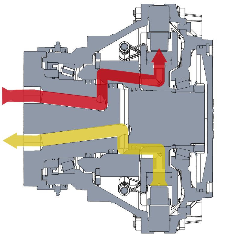
All hydraulic connections of the motor are on the shaft mating surface.
• WORKING LINE PORTS (A and B)
The working lines, aka the feed and return lines of the motor are the high pressure
lines meant for running the motor.
• CASE DRAIN LINE PORT (C or C2) and CASE FLUSHING LINE PORT (C1)
The case drain line is the return line from the housing cavity.
Most of the Black Bruin motors are equipped with the case flushing line (C1). The
flushing line is an extra case line. From a charge pump, or an alternative source,
cool oil from reservoir is fed into motor housing through the flushing line (C1).
The case drain line is marked with C. Motors with case flushing line C1 have a case
drain line marked with C2. The case drain line is used for case drain and returning
flush oil. To ensure motor functionality, C1 line has to be either plugged or used for
flush flow in. C2 is always used for case drain flow out. Do not use C1 as case drain
line.
• BRAKE PRESSURE PORTS (D, D2a and D2b)
The motors with parking brake have brake release line marked with D.
BBC motors with double brake have service brake pilot lines marked with D2a and
D2b.
• BRAKE FLUSHING LINE PORTS (F1 and F2)
BBC motors with double brake have service brake flushing lines marked with F1
and F2.
• PILOT LINE PORTS (Y or Y1 and Y2)
The pilot line is meant for controlling a 2-speed or 4-speed motor (see Multi-speed
motors on page 29).
Note:
The figures represent motor connections of specific models and are
therefore only suggestive. For detailed information consult the motor
manufacturer or its representatives.
36 Product ManualSystem Design
4.3 External freewheeling valve
The external freewheeling valve is used for disengaging the motor during motion (see
Mechanical freewheeling on page 27).
The freewheeling valve should be normally open, so that the motor will disengage
when the control system is off.
When the motor is disengaged the case drain port (C) should be connected as directly
as possible to the working line ports A and B.
There are multiple possibilities for the external freewheeling valve. Some examples of
these possibilities are described in this chapter.
MECHANICAL FREEWHEELING, CHECK MECHANICAL FREEWHEELING, 2/2 VALVE
VALVE
C1
C2
C1
C2
A
A
B
B
*
Min. Min.
3 bar 3 bar
Figure 34. Motor with mechanical free- Figure 35. Motor with mechanical free-
wheeling, external freewheeling valve and wheeling and a 2/2-valve to depressurize
check valve. work lines to case drain (open loop).
Product Manual 37System Design
MECHANICAL FREEWHEELING, CLOSED HYDROSTATIC FREEWHEELING, OPEN
LOOP LOOP
C1
C2
C1
C2
A
A
B
B
0,5 bar
Min.
3 bar*
Figure 36. Motor with mechanical free- Figure 37. Motor with hydrostatic free-
wheeling and external freewheeling valve wheeling and external freewheeling valve
(closed loop). (open loop).
38 Product ManualSystem Design
HYDROSTATIC FREEWHEELING, CLOSED HYDROSTATIC FREEWHEELING FOR 2-
LOOP SPEED BBC
C1
C2
Y1
C1
C2
A
B
A
B
0,5 bar
Min.
3 bar
*
Figure 39. 2-speed BBC motor with hydro-
Figure 38. Motor with hydrostatic free- static freewheeling and external free-
wheeling and external freewheeling valve wheeling valve in open loop system. Maxi-
(closed loop). mum case drain pressure 2 bar.
4.4 Hydraulic fluid
4.4.1 Motors in parallel or series circuit
The traction of a vehicle may be increased by connecting multiple motors in parallel
or in series.
A single powered wheel may transmit only a certain amount of power to traction. By
dividing the power to multiple wheels, the vehicle gets more traction. This is
advantageous especially in slippery operating conditions.
Product Manual 39System Design
PARALLEL CIRCUIT
Figure 40. Two motors in parallel circuit.
Two motors in parallel circuit generate double torque and run half slower than one
motor with the same flow rate and pressure.
Note:
The flow distribution of the motors must be ensured, if the operating
conditions are very slippery or if some of the powered wheels carry much
smaller load. The system prefers to rotate only the motor, which has the
least resistance.
The flow distribution may be done by sizing the working lines to a certain
flow rate or by throttling them slightly.
Ordinary flow divider valve can not be used in most cases, because its
resistance of flow increases too much as the speed of the vehicle
increases.
The flow distribution is usually required only when starting to move the
vehicle. A reliable solution is a flow divider valve, which can be bypassed
or switched on when necessary.
Figure 41. A pilot controlled flow divider valve.
SERIES CIRCUIT
Figure 42. Two motors in series circuit.
Two motors in series circuit generate same torque and rotate as fast as one motor
with the same flow rate and pressure.
Attention:
The minimum pressure and a sufficient feed flow must be ensured for all
motors.
The use of series circuit is challenging and therefore is not recommended.
40 Product ManualSystem Design
4.4.2 Hydraulic fluid type
Black Bruin hydraulic motors are designed to work with hydraulic fluids based on
mineral oil. Consider the following requirements when choosing hydraulic fluid:
• Hydraulic oils in accordance with ISO 6743-4 are recommended to be used.
• Motor oils in accordance with API-grades SF, SG, SH and SL may also be used.
• Fire resistant hydraulic fluids HFB and HFC or similar may be used under certain
circumstances.
4.4.3 Hydraulic fluid properties
Requirements concerning the hydraulic fluid properties:
• The recommended fluid viscosity range for constant use is 25 - 50 cSt.
• The minimum permissible intermittent viscosity is 15 cSt.
• The maximum permissible viscosity during motor startup is 1000 cSt.
• The viscosity index must be at least 100.
• The water content of hydraulic oil should be less than 500 ppm (0,05 %).
• The hydraulic fluid must reach score 10 on a wear protection test FZG A/8,3/90 in
accordance with ISO 14635-1 (DIN 51354)
• The effect of the additives improving the viscosity index can decrease during
operation.
Note:
Temperature has a significant effect on the viscosity and the lubricating
capability of the hydraulic fluid. Take into consideration the real operating
temperature when defining the fluid viscosity.
The need for service and the overall service life may be improved by using
hydraulic fluids with higher viscosity. In addition higher viscosity may
improve the running smoothness.
4.4.4 Hydraulic fluid cleanliness
Hydraulic fluid must fulfill cleanliness level 18/16/13 in accordance with ISO 4406
(NAS 1638 grade 7).
Note:
The purity of the hydraulic fluid has a significant effect on the need for
service and the overall service life of the motor.
4.5 Operating pressures
4.5.1 Case pressure
The case pressure of the motor affects the lifetime of the sealing. It is recommended
to maintain as low case pressure as possible.
When the motor is running, the permissible average case pressure is 2 bar and the
highest permissible intermittent case pressure is 10 bar.
When the motor is not running, the highest permissible constant case pressure is 10
bar.
Make sure that the motor case is always full of oil.
Product Manual 41System Design
Attention:
Running the motor with higher than allowed case pressure shortens the
service life of the motor.
Note:
The lifetime of the sealing may be improved with an accumulator, which
cuts the pressure peaks that are higher than the pre-charge pressure of
the accumulator.
Recommended pre-charge pressure is 2 bar and the displacement should
be about 25 % of the motor displacement. The accumulator should be
connected to the case drain line port as close to the motor as possible.
If motor is placed above the reservoir, add check valve with 1 bar (15 psi)
pressure to case drain line to ensure case oil fill. Maximum continuous
case pressure 2 bar.
4.5.2 Pilot pressure
BB motors BBC motors
404VVVY2/340 C2V2E1Y0AA
405VVVY2/340 C3V2E1Y0AA
406VVVY2/340 C5V2E1Y0AA
407VVVY2/340 C5V7E1Y0AA
The pilot pressure is used to engage the options of the multi-speed motors.
The recommended pilot pressure is 15 to 30 bar and the maximum allowed pilot
pressure is 350 bar.
Attention:
Over 30 bar pilot pressure causes case pressure peaks. This effect should
be minimized with an orifice in the pilot line. Recommended orifice size is 1
mm.
4.5.3 Working line pressure
WORKING PRESSURE
The working pressure is the high pressure that generates the output torque of the
motor. The following values for the working pressure are in the technical data (see
Technical data BB series on page 10 and Technical data BBC series on page 12):
• PEAK PRESSURE
The value of the peak pressure is the maximum allowed value of the working
pressure. Make sure the working pressure does not exceed this value under any
circumstances.
• INTERMITTENT PRESSURE
The value of the intermittent pressure is a permissible value of the working
pressure for a reference period of one minute (1 min). The working pressure may
exceed this value for 10 % of the time during the reference period (for 6 seconds).
MAXIMUM PRESSURE
Unless governed by the power limit, oil temperature or oil viscosity, the maximum
pressure is the maximum continuous work pressure.
42 Product ManualSystem Design
Motor life depends on average speed and pressure. The higher the pressure, the
shorter the expected life. For Lh10 calculations, please consult the manufacturer.
MINIMUM PRESSURE
The minimum pressure is a low pressure required in the working lines, which ensures
the motor stays engaged when running. The motor is engaged when the pistons of
the motor stay constantly connected to the cam ring. The minimum pressure
guarantees continuous contact between cam rollers and cam ring.
The minimum pressure is maintained with charge pressure. Type of the hydraulic
system affects the implementation.
• CHARGE PRESSURE
In closed loop hydraulic system the charge pressure is usually used as the
minimum pressure.
In open loop hydraulic system the charge pressure may be done by a suitable
pressure reducing valve.
Attention:
Too low pressure in the working lines causes the pistons to disconnect
from the cam ring when the motor is running. The effect of this is
clattering noise when the pistons reconnect.
Constant use with too low working line pressure may cause premature
wear or failure of the motor.
Note:
Minimum work line pressure values are given at zero case pressure. To
calculate system specific minimum pressure, add case pressure to the
minimum pressure value from the chart.
The required minimum pressure depends on the rotational speed and case pressure.
Recommended values for the minimum pressure at zero case pressure are on the
following figures:
Product Manual 43You can also read