Mobile Valves Proportional - Load Sensing Model CLS100
←
→
Page content transcription
If your browser does not render page correctly, please read the page content below
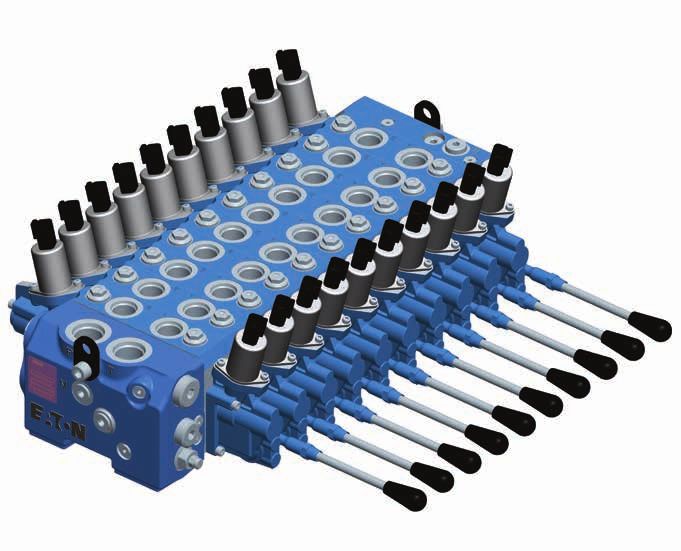
Mobile Valves
Proportional - Load Sensing   350 bar     Up to 10 sections
Model CLS100                  100 L/min   Eaton Pro-FX™Compliant
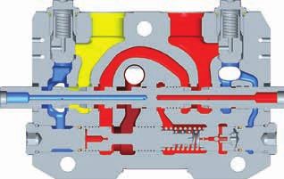
Table of contents

Description                                                                                     Page No.

Specifications and performance       4–7
      Specifications and performance		 4
      Product overview              5-7
CLS load sense sectional mobile valve                                           8-16
      Ordering example		 8
      Model code for valve bank 		 9
      Tie Rod Kits	 10
      CLS100 with manual actuation and enclosed lever box - Installation view	 11
      CLS100 with electrohydraulic actuation - Installation view	 12
      Typical curves                                                           13-16
      Typical work port auxiliary valve curves                                    17
Model code for valve bank inlet                                                                       18
CLS inlet – Configuration                                                                             19
CLS inlet – Relief valve options                                                                      20
CLS inlet – Dump valve options                                                                        21
Model code for sections                                                                               22
Features compatibility table                                                                          23
Valve section options – Compensation                                                                  24
Valve section options – Actuation for hydraulic control                                               25
Valve section options – Actuation for electrohydraulic control                                        26
Valve section options – Actuation for manual control                                                  27
Valve section options – Spool type and spool return action                                            28
Valve Section options – Port A and Port B spool flows and coil type                                   29
Valve section options – Port A and Port B functions and settings                                      30
Valve section options – Load sense relief options and setting                                      31-32
Valve section options – Spool stroke limiter or position indicator and lever kit                   33-34
Valve section options – Build type                                                                    35
Model code for valve bank end cover                                                                   36
CLS assembly – End covers                                                                          37-38
Mid-Inlet and transistion plates                                                                      39
Hydraulic fluid recommendations                                                                    40-41
Viscosity and cleanliness requirements                                                                42

2                EATON CLS100 Load Sense Sectional Mobile Valves E-VLVM-CC001-E4 January 2021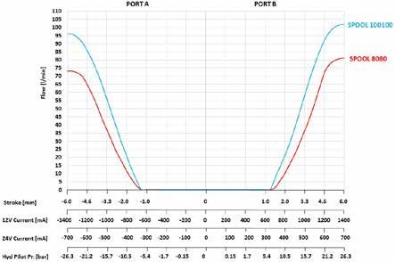
Eaton’s CLS
Load Sense Sectional
Mobile Valve
Eaton’s new CLS100 Load Sensing Sectional Mobile                 install both pre and post compensated sections in the
Valve is a pre and post compensated mobile valve with a          same valve bank; the CLS100 allows you to prioritize work
highly versatile design. This modularity is demonstrated         functions to accelerate productivity, improve machine
through the availability of valve banks with up to 10            efficiency, and enhance the safety characteristics of the
sections, a number of spool types and actuation options,         machine.
mid-inlets, custom inlet manifolds and transition plates.        Improve your machine performance with the newest load
With this flexibility, you can design your valve to meet         sensing valve to market, the Eaton CLS100.
the requirements of your machine. Add in the ability to

Features and benefits                                                                                 Typical applications
•L
  oad sense circuit design   •E
                                lectro-proportional spool       • Special features available        • Excavator – Multiple sizes
 is a parallel circuit with    control achieved through             for additional design             • Forestry
 closed center spools.         a PWM proportional                   flexibility:
 Available with inlet          pressure reducing                                                      • Refuse trucks
                                                                   -S
                                                                     ectional load sense
 options to support            solenoid valve controlling           relief on pre and post            • Forklift
 both fixed and variable       pilot pressure to spool              compensated sections              • Agricultural machinery
 displacement pumps            ends to maintain spool
                               position                            - Adjustable spool stroke         • Truck mounted cranes
•B
  oth pre and post comp                                              limiting device
 sections available in same   •O
                                ptional manual,                                                      • Marine
 valve assembly                hydraulic and                       -P
                                                                     arallel connection of
                               Electro-hydraulic controls           multiple valve banks
•F
  lexible design with up
 to 10 sections                with lever overrides                - Work port relief with
                                                                      anti cavitation
                                                                   - Available fourth
                                                                      position float

                                       EATON CLS100 Load Sense Sectional Mobile Valves E-VLVM-CC001-E4 January 2021               3   3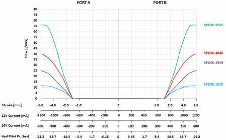
Specifications and performance

CLS100 Load Sense Sectional Mobile Valve
Rated pressure                              Inlet                            350 bar (5076 psi)
                                            Work port                        350 bar (5076 psi)
                                            Tank port                        10 bar (145 psi)
                                            Pilot Drain Port (D1/D2)         5 bar (73 psi)
Rated inlet flow		                                                           150 lpm (39.6 gpm)
Rated workport flow                         Post Compensated -               100 lpm (26.4gpm) @ 14 bar differential pressure
                                            Pre Compensated -                80 lpm (21.1gpm) @ 14 bar differential pressure
                                            Pre Compensated -                100 lpm (26.4gpm) @ 17 bar differential pressure
Fluid cleanliness and viscosity             See Hydraulic Fluid Recommendations Bulletin 03-401
Ambient operating temperature range         -40˚C / 60˚C (-40˚F / 140˚F)
Oil temperature operating range             -25˚C / 80˚C (-13˚F / 176˚F)
Construction		Sectional
Work sections		                                                              1-10
Maximum leakage, cylinder workport to tank		                                 11 cc per minute at 100 bar (1450 psi)
Port types                                  Inlet and Tank                   SAE-12 or BSP G 3/4
                                            Work Ports A and B               SAE-10 or BSP G 1/2
                                            Inlet Pr Gauge port “M”,         SAE-6 or BSP G 1/4
                                            LS port and Drain port           SAE-6 or BSP G 1/4
                                            Hydraulic Pilot                  SAE-6 or BSP G 1/4
Work section options                        Spools                           Double acting (4 way) cylinder
		                                                                           Double acting (4 way) cylinder with 4th position float
		                                                                           Bi-directional (4 way) motor, full open to tank in neutral
                                            Actuation                        Hydraulic with top ports
		                                                                           Hydraulic with top ports and lever override
		                                                                          Hydraulic with end ports
		                                                                           Hydraulic with end ports, lever override, and configured for EH pilot valve installation
		Electrohydraulic with lever override
                                                                             Electrohydraulic only
                                                                              Electrohydraulic with hydraulic ports and lever override
                                                                               Electrohydraulic with hydraulic ports
                                                                                Manual with enclosed lever box
                                                                                 Manual with exposed spool connection
Coil voltages		                                                                  12 Volt DC
		                                                                               24 Volt DC
Coil connectors		                                                                Integral Deutsch DT04-2P
		                                                                               Amp Jr. Timer connector 106462-1
Electrohydraulic interface		                                                     Eaton HFX programmable controllers and Pro-FX™ application software

4                    EATON CLS100 Load Sense Sectional Mobile Valves E-VLVM-CC001-E4 January 2021
CLS Load Sense Sectional Mobile Valve
Product Overview
Operating principle (Post Comp) Single section
The CLS valve, completely pressure compensated, Referencing the picture to the left reveals some aspects
guarantees great controllability to all actuations, making of system functionality. From the inlet line, the high
workport flow dependent only on metering area (spool pressure flow passes across the metering area and down
position). When flow saturation occurs the system reacts to the local compensator. The metering area, according to
by implementing an equal reduction of pressure margin the pressure margin, controls the total amount of flow to
across all spools, generating a proportional reduction of the work-port selected by the main spool.
workport flow. The load sensing signal, picked up downstream of the
local compensator, feeds the common load-sensing
line. When a single section is actuated, the local
Work section flow path P-A and B-T (post comp)
compensator fully opens to the left side, reaching
2 1 its complete balanced position. The control of the LS
system is achieved by the inlet compensator for fixed
B A displacement pumps or the pump compensator for
variable displacement pumps.
Spool
stroke
=7mm P T Multi-section
When two or more sections are actuated, only the
function characterized by the highest pressure (dominant)
is involved in the LS signal transmission. The other
functions become directly dependent on it (slaves). The
common LS line transfers the signal from the dominant
local compensator to all dependent compensators.
Driven by the LS signal, the unbalanced slave
5 4 3 compensators activate the pressure compensation
creating an artificial pressure drop able to keep pressure
margin nominally the same on all the spools. Work-port
Legend: flow becomes only a function of metering area making
the system totally load independent.
1 Inlet line (high pressure)
2 Metering notches
Flow sharing section
3 Load sensing line
Saturation occurs when the total amount of flow required
4 Local compensator by the valve bank is greater than the maximum pump
5 Metering spool flow rate. In this condition the system is not able to
maintain the nominal pressure margin, reducing the
margin according to real flow demand. As a result all
the local section compensators experience the same LS
signal and the same pressure drop is applied to different
metering areas, reducing work-port flows proportionally in
order to keep all actuations completely under control.
EATON CLS100 Load Sense Sectional Mobile Valves E-VLVM-CC001-E4 January 2021 5CLS Load Sense Sectional Mobile Valve
Product Overview
Operating principle (Pre Comp Section) Single section
The unique design of CLS valves allows one or more Referencing the picture to the left reveals some aspects
precompensated sections to be designed into a of system functionality. From the inlet line, the high
normally configured valve. The advantage of having pressure flow passes across section compensator
a precompensated
— March 2, 2017 6:19 PM section available within a post-com- where the spring provides sectional margin pressure
pensated system (a rather unique configuration among which is addition to the inlet compensator spring
flow sharing systems) lies in the fact that a priority flow pressure. The metering area comes into picture after the
function can be guaranteed. sectional compensator as this being pre compensation.
In a saturation condition, all post compensated sections The metering area, according to the pressure margin,
will proportionally reduce their delivered flows, while the controls the total amount of flow to the work-port
pre-compensated section will keep a constant delivered selected by the main spool.
flow in order to guarantee the priority of the function. Pressure differential acting on the compensator spool
is picked from either side of the main metering orifice.
Compensator spools references the load sense signal
Work section flow path P-A and B-T (pre comp) picked up before the load sense shuttle. Pump to
load sense pressure differential is controlled by
1 2 compensator springs
B A
Multi-Section
Spool When flow demand exceeds flow supply the
stroke P T lowest loaded section takes priority over the highest
= 6mm loaded section
Flow Priority
CLS100 offers a precious additional feature: The possibility
to mix pre and post compensated technologies in single
bank, to improve the control capabilities and manage
flows with different priorities.
5 4 3
Work section flow path P-B and A-T (pre comp)
Legend:
1 Inlet line (highBpressure) A
2 Metering notches
Spool 3 Load sensing line Spool
stroke T stroke
= 7mm
4 Local compensatorP = 6mm
5 Metering spool
6 EATON CLS100 Load Sense Sectional Mobile Valves E-VLVM-CC001-E4 January 2021CLS Load Sense Sectional Mobile Valve
Product Overview
The CLS100 valve line allows the customer the ability to The following schematics show an example of an all post-
combine pre and post compensated valve sections in the compensated system, and a system with an integrated
same valve bank. The pre compensated section acts as pre compensated section.
a priority flow sharing function by diverting flow to the
pre compensated function first, then to the remaining
sections in the bank.
Post compensated
system
LS signal Dump valve
LS signal MRV
A1 B1 A2 B2 A3 B3 A4 B4
T
D2
P R
M LS D1
Inlet compensator Post local compensator
Internal press. reducing valve
Full flow relief valve
Pre compensated
system
Inlet compensator
LS Signal dump valve
LS signal MRV Pre-compensated section
A1 B1 A2 B2 A3 B3 A4 B4
T
D2
P R
M LS Full flow relief valve Internal press. reducing valve D1
Post local compensator Pre local compensator
EATON CLS100 Load Sense Sectional Mobile Valves E-VLVM-CC001-E4 January 2021 7CLS Load Sense Sectional Mobile Valve
Ordering example
Valve bank order 1. Inlet CLS100LSL125000ZZ00B
example 2. Section 1 CLS101PESDA040040CP000P000Z000ZBL00B
3. Section 2 CLS101PESDA040040CP000P000Z000ZBL00B
4. Section 3 CLS101PESDA040040CP000P000Z000ZBL00B
5. End Cover CLS102GS00B
6. CLS100/3 Tie Rod Kit 6042571-003
7. Paint 00- None
0B- Glossy Blank
AU- Standard Flat Black
BD- Yellow
0C- Red
CD- Eaton Blue (Primer)
0K- Green
Note: Repeat section model code for additional sections.
6
5
4
3
2
1
8 EATON CLS100 Load Sense Sectional Mobile Valves E-VLVM-CC001-E4 January 2021Model code for valve bank
CLS100 XX X X X XXX XXX X X XXXXX X X 00 00 B
1-6 7-8 9 10 11 12-14 15-17 18 19 20-24 25 26 27-28 29-30 31
1-6 Product Series 12-14 Load Sense Relief* 20-24 Sections #,@ 27-28 Paint/Coating***
Setting 00 – None
CLS100 – Load Sense XXXXX –
Sectional Mobile Valve: XXX – 3
Digit Load Sense 5 Digit work section part 0B – Glossy Black
Standard Valve Bank Inlet Relief Setting in 5 number ( Assigned by AU – Standard Flat Black
Bar Increments, Eaton engineering )
BD – Yellow
7-8 Number of Sections Code 000 if none Repeat these 5 digit
0C – Red
work section part
XX – Replace XX with 15-17 Full Flow Relief * number as per build CD – Eaton Blue (Primer)
number of sections Setting requirement. 0K – Green
(e.g. 01 or 02,.…
XXX – 3
Digit Full Flow Total number of digits
up to 10 ) 29-30 Special Features
Relief Setting in 5 for 10 section bank
This number will vary Bar Increments, for referring here are 00 – No special features
as per requirement of Code 000 if none 50 digits.
work sections in bank 31 Design Level
assembly 18 Inlet Dump Valve 25 End cover **
B – Latest design
9 Inlet Type F – Full Flow Dump Valve F – Electrohydraulic with
L – LS Dump Valve external end drain
L – Load Sensing
Z – No Dump Valve G – Electrohydraulic with
(Variable disp. pumps)
external side drain
U – Unload for Open
H – Hydraulic or manual
Center (fixed disp. 19 Inlet Coil
with internal drain
pumps)
A – 12V Coil with DIN K – Hydraulic or manual
Connector with external drain
10 Inlet Ports
B–2 4V Coil with DIN N – Electrohydraulic with
B – BSP (G3/4 P&T, G1/4 Connector internal drain
LS&M) C–1 2V Coil Deutsch
S – SAE (-12 P&T, -6 Connector 26 End cover ports
LS&M) D–2 4V Coil Deutsch B – BSP (G1/4 pilot drain)
Connector
11 Inlet Reliefs* S – SAE (-6 pilot drain)
E – 12V Coil AmpJr
D – LS & Full Flow Reliefs Connector
L – LS Relief Only F–2 4V Coil AmpJr
R – Full flow relief only Connector
Z – No Reliefs Z – No Coil
Notes:
* Refer Inlet model code for detail, Page 18
** Refer End cover model code for detail, Page 36
*** All paint is finish coat with exception to Eaton Blue, which is a primer coat.
# Position for sections can vary from 20 to 69 digits as per number of sections required in bank assembly.
Based on this next features position will change.
@ When selecting Actuation sequence for work section for LH build it is required to have A,C,L should be stacked first near inlet
section and to be followed by B,D,E, & G to avoid interference between section
When selecting Actuation sequence for work section for RH build it is required to have B,D,E & G should be stacked first near
inlet section and to be followed by A,C,L to avoid interference between section
EATON CLS100 Load Sense Sectional Mobile Valves E-VLVM-CC001-E4 January 2021 9CLS Load Sense Sectional Mobile Valve
Tie Rod Kits
Tie rod kits are required to complete a valve bank
assembly. Tie rod length depends on the number of
sections in the bank. Each tie rod kit includes three (3) tie
Rods, three (3) nuts and three (3) washers.
Tie rod kits for CLS100 bank assembly
Tie Rod Length
Kit Desc. Tie Rod Kit (mm)
CLS100/1 1 Sect. 6042571-001 102
CLS100/2 2 Sect. 6042571-002 140
CLS100/3 3 Sect. 6042571-003 178
CLS100/4 4 Sect. 6042571-004 217
CLS100/5 5 Sect. 6042571-005 255
CLS100/6 6 Sect. 6042571-006 293
CLS100/7 7 Sect. 6042571-007 331
CLS100/8 8 Sect. 6042571-008 370
CLS100/9 9 Sect. 6042571-009 408 Tie rod
CLS100/10 10 Sect. 6042571-010 445 Washer
Nut
Tie rod kit
Tightening : 40 Nm
Tie rod kits for CLS180 sections for CLS180 to CLS100
transition plate part #6045191-001
Tie Rod Kit Desc. Tie Rod Kit Length (mm)
CLS180/1 1 Sect. 6044401-001 156
Tie rod
CLS180/2 2 Sect. 6044401-002 202
CLS180/3 3 Sect. 6044401-003 249 Washer
CLS180/4 4 Sect. 6044401-004 295
Tie rod kit
CLS180/5 5 Sect. 6044401-005 341
Nut
CLS180/6 6 Sect. 6044401-006 387
CLS180/7 7 Sect. 6044401-007 434
CLS180/8 8 Sect. 6044401-008 480
CLS180/9 9 Sect. 6044401-009 526
Tightening Torque: 70 Nm
Note:
This kit includes 3 tie rods, 3 nuts, 3 washers and used on CLS180 side interface.
10 EATON CLS100 Load Sense Sectional Mobile Valves E-VLVM-CC001-E4 January 2021CLS Load Sense Sectional Mobile Valve
CLS100 with manual actuation and enclosed lever box
Units: mm
105.6
40.5
80.5 24.5
73.0
51.0
82.5 21.5 82.0
57.5
18.9 M8 80.3
210.0
4.8
30.5 49.0 38.0 38.0 43.0
Optional lever
location at 90˚ Y (233.1)
ø12.7 mm for lifting
at 2 places (Lever not shown) M8 12.0
123.0
120.8 115.5 111.5
55.5 51.0
139.5
63.0 38.0 38.0 38.0 24.0
18.0 X (171.0)
M1O X 1.5 12.0
at 3 places
for mounting
40.5
41.5
79.0 114.5
Dimension Number of sections
/1 /2 /3 /4 /5 /6 /7 /8 /9 /10
X (mm) 95 133 171 209 247 285 323 361 399 437
Y (mm) Max 157 195 233 272 310 348 386 425 463 500
Weights (kg) 14.5 18.5 22.5 26.5 30.5 34.5 38.5 42.5 46.6 50.5
EATON CLS100 Load Sense Sectional Mobile Valves E-VLVM-CC001-E4 January 2021 11CLS Load Sense Sectional Mobile Valve
CLS100 with electrohydraulic actuation
Units: mm
105.6
65.0
80.5 24.5 78.5
51.0
21.5
82.5 86.5
19.0
78.5
4.8
30.5 49.0 38.0 38.0 49.0
Y (239.1)
66.5 Ø 12.5 mm for lifting
at 2 places
16.0
163.5
113.3 120.8
111.5
31.0 86.0
67.5
49.0
M8 33.5
101.0 38.0 38.0 30.0 78.5 165.0 65.0
Lever location
(Lever not shown)
18.0 X (171.0)
M10 X 1.5 12.0
at 3 places
for mounting 45.0
41.5 41.5
79.0
120.0
Dimension Number of sections
/1 /2 /3 /4 /5 /6 /7 /8 /9 /10
X (mm) 95 133 171 209 247 285 323 361 399 437
Y (mm) Max 163 201 239 278 316 354 392 431 469 506
Weights (kg) 15 19.5 24.0 28.5 33.0 37.5 42.0 46.5 51.0 55.5
12 EATON CLS100 Load Sense Sectional Mobile Valves E-VLVM-CC001-E4 January 2021CLS Load Sense Sectional Mobile Valve
Typical curves
Inlet compensator pressure drop (P-T) 30
Fixed displacement system: pressure drop
across the inlet compensator as function of 25
pump flow
20
pressure [bar]
15
10
5
0
0 10 20 30 40 50 60 70 80 90 100 110 120 130 140 150
flow [l/m]
LS signal pressure relief valve 350
Fixed displacement system: LS Signal 300
pressure relief valve characteristic
250
pressure [bar]
200
150
100
50
0
0 10 20 30 40 50 60 70 80 90 100 110 120 130 140 150
flow [l/m]
Full flow dump valve 8
Fixed displacement systems: pressure drop 7
across open electric dump valve as function
of pump flow 6
pressure [bar]
5
4
3
2
1
0
0 10 20 30 40 50 60 70 80 90 100 110 120 130
flow [l/m]
EATON CLS100 Load Sense Sectional Mobile Valves E-VLVM-CC001-E4 January 2021 13CLS Load Sense Sectional Mobile Valve
Typical curves
Post compensated 14 bar ∆ p between load sense and inlet pressure
spool flow
characteristic 100 Spool 100100
Flow on ports A and
B as function of spool
Spool 8080
stroke, pilot pressure, 80
control current. 70
Spool 6565
60
Spool 5050
flow [l/min]
50
40 Spool 4040
30
Spool 2525
20
10 Spool 1010
0
stroke [mm] stroke [mm]
-7 -6 -5 -4 -3 -2 -1 0 +1 +2 +3 +4 +5 +6 +7
12V current [mA] 12V current [mA]
1300 1160 1020 880 740 600 600 740 880 1020 1160 1300
24V current [mA] 24V current [mA]
650 580 510 440 370 300 300 370 440 510 580 650
Hydraulic pilot [bar] Hydraulic pilot [bar]
20,1 17,3 14,5 11,8 9 6,2 6,2 9 11,8 14,5 17,3 20,1
Spool flow versus 140 Spool 100100
delta pressure
120
With post comp, maximum Spool 8080
flow is a function of the
delta P created by the 100
variable displacement pump Spool 6565
80 Spool 5050
Flow at full stroke (l/min)
60
Spool 4040
40
Spool 2525
20
Spool 1010
0
12 14 16 18 20 22 24 26
Pressure [bar]
14 EATON CLS100 Load Sense Sectional Mobile Valves E-VLVM-CC001-E4 January 2021CLS Load Sense Sectional Mobile Valve
Typical curves
Pre compensated spool
flow characteristic
Flow on ports A and B as
function of spool stroke,
pilot pressure, control
current.
14 bar ∆ p between load sense and inlet pressure
80 lpm Rated flow requires 14 bar ∆P between inlet and load
sense & requires special section compensator spring
100 lpm Rated flow requires 17 bar ∆P between inlet and load
sense & requires special section compensator spring (need special
inlet with 17 bar margin spring when used with open centre inlet )
EATON CLS100 Load Sense Sectional Mobile Valves E-VLVM-CC001-E4 January 2021 15CLS Load Sense Sectional Mobile Valve
Typical curves
Post compensated four 100
position float spool 90
characteristic
80 Spool 8080
Flow and float position as
function of spool stroke, 70
pilot pressure, control Spool 6565
FLOAT POSITION
current 60
flow [l/min]
50
40 Spool 4040
30
Spool 2525
20
10 Spool 1010
0
stroke [mm]
0 +1 +2 +3 +4 +5 +6 +7 +11,5
12V current [mA]
600 680 760 840 920 1000 min. 1800
24V current [mA]
300 340 380 420 460 500 min. 900
Hydraulic pilot [bar]
6 7,8 9,6 11,4 13,2 15 min. 30
16 EATON CLS100 Load Sense Sectional Mobile Valves E-VLVM-CC001-E4 January 2021CLS Load Sense Sectional Mobile Valve
Typical work port auxiliary valve curves
400
Work Port Relief Valve (relief mode)
Pressure characteristic as function of flow 350
300
250
pressure [bar]
200
150
100
50
0
0 10 20 30 40 50 60 70 80
flow [l/m]
7
Work Port Relief Valve (anti-cav mode)
Opening and pressure characteristic 6
as function of flow
5
4
pressure [bar]
3
2
1
0
0 10 20 30 40 50 60 70 80
flow [l/m]
EATON CLS100 Load Sense Sectional Mobile Valves E-VLVM-CC001-E4 January 2021 17Model code for valve bank inlet
CLS100 X X X XXX XXX X X 00 B
1-6 7 8 9 10-12 13-15 16 17 18-19 20
1-6 Product Series 9 Inlet Reliefs 13-15 F
ull Flow Relief 17 Inlet Coil
Setting A – 12V Coil with DIN
CLS100 – Load Sense D – LS & Full Flow Reliefs
Sectional Mobile Valve: L – LS Relief Only XXX – 3 Digit Full Flow Connector
Standard Valve Bank Inlet R – Full flow relief only* Relief Setting in 5 B – 24V Coil with DIN
Bar Increments, Connector
Z – No Reliefs Code 000 if none
7 Inlet Type C – 12V Coil Deutsch
Note: 90-350 bar
10-12 L
oad Sense Relief ”Settings above 350 bar
Connector
L – Load Sensing Setting should only be used with D – 24V Coil Deutsch
(Variable disp. pumps) approval of duty cycle” Connector
XXX – 3 Digit Load Sense
U – Unload for Open Center E – 12V Coil AmpJr
Relief Setting in 5 Inlet Dump Valve
(fixed disp. pumps) 16 Connector
Bar Increments,
Code 000 if none F – Full Flow Dump Valve F – 24V Coil AmpJr
8 Inlet Ports Note: 50-350 bar LS Relief Connector
L – LS Dump Valve
B – BSP (G3/4 P&T, G1/4 setting should be minimum Z – No Coil
40 Bar lesser than Full flow Z – No Dump Valve
LS&M) relief setting. Anything
S – SAE (-12 P&T, -6 LS&M) above 350 bar is rated for pecial Features
18-19S
intermittent operation. 00 – No special features
Consult engineering for duty
cycle acceptance above 20 Design Level
350 bar
B–L atest design
* R - Full flow relief only option is
not recommended. Inlet LS relief
is recommended, which limits
system pressure and gives
better efficiency.
Notes:
1. Cannot have full flow relief valve and full flow dump valve in same inlet. Full flow relief valve and full flow dump valve cavities are different,
so these are not interchangeable.
2. Transition plates and mid-inlets are available on request.
18 EATON CLS100 Load Sense Sectional Mobile Valves E-VLVM-CC001-E4 January 2021CLS inlet – Configuration
Model code positions 7
L - Load sensing
T T
Closed center inlet section P
for variable displacement
pumps
The inlet section with
L configuration enables
control valve usage with
variable displacement
pumps. With this
configuration the presence LS
of LS relief valve is suitable
to adjust the system
maximum pressure. LS
electric dump valve can
also be added as safety
device. An additional
full flow relief valve can
be added to protect P
the system from pump
regulator failures.
M LS
SCHEMATIC FOR LOAD SENSING INLET
T T
U - Unload for open P
center
Open center inlet section
for fixed displacement
pumps
The inlet section with
U configuration enables
control valve usage with
fixed displacement pumps.
With this configuration
the presence of LS relief
valve is suitable to adjust
the system maximum
pressure. Full flow electric
dump valve can also be
added as safety device.
P
M Ls
SCHEMATIC OF UNLOAD FOR OPEN CENTER INLET
EATON CLS100 Load Sense Sectional Mobile Valves E-VLVM-CC001-E4 January 2021 19CLS inlet – Relief valve options
Model code position 9
T
D - LS & full flow reliefs
Note: This combination requires that
the Full Flow Relief be set at least 40
bar higher than the LS Relief.
P
M LS
SCHEMATIC OF OPEN CENTER D - LS & FULL
FLOW RELIEFS
T
L - LS relief only
P
M Ls
SCHEMATIC OF OPEN CENTER INLET L - LS
RELIEF ONLY
T
R- Full flow relief only
P
M Ls
SCHEMATIC OF OPEN CENTER INLET R- FULL
FLOW RELIEF ONLY
T
Z - No reliefs
P
M Ls
SCHEMATIC OF OPEN CENTER INLET Z-NO RELIEFS
20 EATON CLS100 Load Sense Sectional Mobile Valves E-VLVM-CC001-E4 January 2021CLS inlet – Dump valve options
Model code positions 16 & 17
T
Coil
F - Full flow electric dump valve
P
M Ls
SCHEMATIC OF OPEN CENTER INLET F- FULL
L - LS electric dump valve FLOW DUMP VALVE
Coil
T
T P
P
M Ls
SCHEMATIC OF OPEN CENTER INLET L- LS
ELECTRIC DUMP VALVE
F - Full flow dump valve L - LS Electric dump valve
T P
T P
Coil and Connectors specifications for inlet section
Coil
Connector types Ingress Resistance Connector Coil Duty Coil
Option (Deutsch/Amp Jr) Rating R20 (Ω) Material Body Cycle Insulation Power
A A - 12V Coil with DIN Connector IP 65 7
B T P B - 24V Coil with DIN Connector IP 65 28
Zinc Class H
C C - 12V Coil with Deutsch Connector IP 67 7 ED
Nylon plated coil - IEC 85 20.5 W
D D - 24V Coil with Deutsch Connector IP 67 28 100% Standard
steel
E E - 12V Coil with AmpJr Connector IP 65 7
F F - 24V Coil with AmpJr Connector IP 65 28
EATON CLS100 Load Sense Sectional Mobile Valves E-VLVM-CC001-E4 January 2021 21Model code for sections
The following 36 digit coding system has been developed specify a valve with the desired features. All 36-digits
to identify preferred feature options for the CLS100 Load of the code must be present to release a new product
Sense Sectional Mobile Valve series. Use this code to number for ordering.
CLS101 X X X X X XXX XXX X X XXX X XXX X XXX X X X 00 B
1-6 7 8 9 10 11 12-14 15-17 18 19 20-22 23 24-26 27 28-30 31 32 33 34-35 36
11 Spool Action 19 Port A Option Function 28-30
LS
Relief Setting
1-6 Product Series
A – Spring Centered to A – Anti-Cav XXX – 3 Digit Section
CLS101 – Load Sense Neutral LS Relief Setting in
Sectional Mobile Valves R – Relief/Anti-Cav
B – Detent “In” and “Out”* 5 bar increments
P – Plugged - Work port from 50-350 bar
7 Compensation C – Fourth Position Float # Cavities Machined (000 if not Present
E – Fourth Position Float and Plugged or if Using Remote
P – Post-compensated Detent* # Z–N one - Option Port LS Relief)
L – Pre-compensated F – Friction - Hold in No Machining
R–P ost-compensated with Position* T–T ransducer Port Adaptor 31 pool Stroke Limiter
S
Local flow Limiter*** For Work Port Pressure or Position Indicator
N– Non-compensated 12-14 ort A Spool Flow @
P Sensing (Plugged A – Electrohydraulic
Section 005 – 5 l/m option:G1/8 BSP or Section w/Spool
SAE 4) Stroke Limiter
8 Actuation 010 – 10 l/m
B – Hydraulic Section
A – Hydraulic with Top Ports 015 – 15 l/m 20-22 Port
A Option w/Spool Stroke Limiter
B – Hydraulic with Top Ports 025 – 25 l/m Setting
P – Electrohydraulic Spool
and Lever Override XXX – 040-350 (3 digit, Position Indicator
035 – 35 l/m
C – Hydraulic with End Ports fixed setting in 10 bar
040 – 40 l/m increments), relief valve Z – None
D – Hydraulic with End pressure setting, port A
Ports, Lever Override, 050 – 50 l/m 32 Lever Kits
and Configured for EH 065 – 65 l/m
Pilot Valve Installation
23 Port B Option Function A – 135mm (5.5”)
080 – 80 l/m A – Anti-Cav Lever Kit
E – Electrohydraulic with
100 – 100 l/m R – Relief/Anti-Cav B – 210mm (8.5”)
Lever Override
P – Plugged - Work port Lever Kit
F – Electrohydraulic Only 15-17 ort B Spool Flow @
P Cavities Machined Z – None
G – Electrohydraulic with
005 – 5 l/m and Plugged
Hydraulic Ports and
Lever Override Z–N one - Option Port 33 Build Type
010 – 10 l/m
H–E lectrohydraulic with No Machining R – Right Hand
015 – 15 l/m T–T ransducer Port Adaptor (Std for Pre Comp)
Hydraulic Ports
L – Manual with Enclosed 025 – 25 l/m For Work Port Pressure L – Left Hand
Lever Box 035 – 35 l/m Sensing (Plugged (Std for Post Comp)
M – Manual with Exposed option:G1/8 BSP or
040 – 40 l/m SAE 4) 34-35 pecial Features
S
Spool Connection
050 – 50 l/m 00 – No special features
065 – 65 l/m 24-26 Port
B Option
9 Port Type Setting 36 Design Level
080 – 80 l/m
XXX – 040-350 (3 digit, B – Latest Design
B – G1/2 BSP (G1/4 Pilot if 100 – 100 l/m fixed setting in 10 bar
Hyd., increments), relief valve
S – SAE, -10 (SAE -6 Pilot 18 Coil
Type pressure setting, port B
if Hyd., C – 12V coil Deutsch
connector 27 Sectional LS Relief Note: @
Pre/Post compensation spools offer
10 Spool Type D – 24V coil Deutsch Option varying flows, please refer page 29 on
applicable spool flow
D – Double Acting (4 Way) connector L – Sectional Load Sense
Relief valve (Applies to * Available with Manual Actuation only
Cylinder E – 12V coil AmpJr
connector Both A & B Ports)**## ** P ost comp Sectional LS relief comes with
F – Double Acting (4 Way) LH build
Cylinder with 4th F – 24V coil AmpJr Y – SAE -4 or G1/8 Port Pre comp Sectional LS relief comes with
Sectional Remote Load RH build
Position Float # connector
Z – No coil Sense Relief valve *** Available with RH build only
H – B
i-Directional (4 Way) (Applies to Both A & B # Available with RH build and post comp
Motor, Full Open to Tank Ports)$ option only
in Neutral ## Sectional LS relief option not available for
Z – No LS Relief EH float actuation
$ Available for pre comp option only
22 EATON CLS100 Load Sense Sectional Mobile Valves E-VLVM-CC001-E4 January 2021 22Features compatibility table
Compatibility chart for spool action options with compensation type
Spool Action (Model code position-11)
C – Fourth Position Float
A – Spring Centered B – Detent “In” E – Fourth Position F – Friction hold
to Neutral and “Out” Hydraulic Electrohydraulic Float Detent (Manual) in Position
Combination RH Build LH Build RH Build LH Build RH Build LH Build RH Build LH Build RH Build LH Build RH Build LH Build
Post comp With Sectional
LS relief • • • • • • •
W/O Sectional
LS relief • • • • • • • • •
Post comp With Sectional
Compensation with local flow LS relief • • • • • •
(Model code limiter
position-7) W/O Sectional
LS relief • • • • • • • •
Pre comp With Sectional
LS relief • • •
W/O Sectional
LS relief • • • •
Compatibility chart for hydraulic and electrohydraulic actuations having manual override option
Compensation (Model code position-7)
Post comp Post Comp with local flow limiter Pre comp
Combination With Sectional LS Relief With Sectional LS Relief W/O Sectional LS Relief With Sectional LS Relief
B – Hydraulic with top ports and RH Build
lever override • •
LH Build
•
D - Hydraulic with end ports, lever RH Build
override and configured for EH pilot • •
valve installation
LH Build
•
E - Electrohydraulic with RH Build
lever override • •
LH Build
Actuation •
(Model code
position-8) F – Electrohydraulic only RH Build
• •
LH Build
•
G - Electrohydraulic with hydraulic RH Build
ports and lever override • •
LH Build
•
H - Electrohydraulic with RH Build
hydraulic ports • •
LH Build
•
EATON CLS100 Load Sense Sectional Mobile Valves E-VLVM-CC001-E4 January 2021 23Valve section options – Compensation
Model code position 7
The CLS family offers an unique additional feature: with different priorities.The following schematics show an
the ability to mix pre and post compensated technologies, example for the two systems.
to improve the control capabilities and manage flows
P- L-
Post compensated (flow sharing) Pre compensated
Available with or without auxiliary valve cavities Available with or without auxiliary valve cavities
Note: Shown with auxiliary valves Note: Shown with auxiliary valves
AB AB
AB AB
Mechanical lever Electrohydraulic Mechanical lever Electrohydraulic
acuation acuation acuation acuation
R-
Post compensated (flow sharing)
with local flow limiter
Available with or without auxiliary valve cavities
Note: Shown with auxiliary valves
Available with RH build only.
AB AB AABB AB AB
Local flow limiterLocal flow limiter Local flow limiter
Mechanical lever Electrohydraulic
acuation acuation
24 EATON CLS100 Load Sense Sectional Mobile Valves E-VLVM-CC001-E4 January 2021Valve section options – Actuation for hydraulic control
Dimensions and configurations for model code position 8
Units: mm
A-
Hydraulic with top ports* 23.5 23.5
1/4”G - 9/16”UNF 1/4”G - 9/16”UNF
Hydraulic actuation (pilot
ports on the top)
(Only with manual and 35.5 35.5
hydraulic section body)
73.0 73.0
78.3 78.3
B-
Hydraulic ports and
lever override* 1/4" G or
9/16" UNF 28.0
Lever actuation and
hydraulic actuation 67.5
(Only with EH type body)
94.3
83.0
C-
Hydraulic with end ports*
Hydraulic actuation (pilot 40.8
23.5 23.5
40.8
ports on the sides) 35.5 35.5
(Only with manual and
hydraulic section body)
1/4”G - 9/16”UNF 1/4”G - 9/16”UNF
73.0 73.0
D-
Hydraulic with End
ports, lever override, and
configured for EH pilot
102.7
valve installation*
Lever and hydraulic
actuation with
electrohydraulic 108.1
arrangement
EATON CLS100 Load Sense Sectional Mobile Valves E-VLVM-CC001-E4 January 2021 25 25Valve section options – Actuation
for electrohydraulic control
Dimensions and configurations for model code position 8
Units: mm
E-
Electrohydraulic with
lever override
152.9
83.0
F-
Electrohydraulic only
Without lever
152.9
65.5
G-
Electrohydraulic with
hydraulic ports and
lever override*
Lever, hydraulic, and 153.0
electrohydraulic actuation
108.1
H-
Electrohydraulic with
hydraulic ports*
Without lever, hydraulic,
and electrohydraulic 153.0
actuation
108.1
Note: * Plastic shipping plugs fitted on hydraulic ports.
26 EATON CLS100 Load Sense Sectional Mobile Valves E-VLVM-CC001-E4 January 2021Valve section options – Actuation for
manual control
Dimensions and configurations for model code position 8
Units: mm
L- M8 M8
Manual with enclosed
lever box
67.5
Lever actuation 60.0
(Only with manual and
hydraulic section body)
25.0
57.5
80.3
M-
Manual with exposed
spool connection
Without lever actuation Ø6.0
(Only with manual and
hydraulic section body) Ø6.0
38.5
44.5
Note: Only available on post compensated sections
EATON CLS100 Load Sense Sectional Mobile Valves E-VLVM-CC001-E4 January 2021 27Valve section options – Spool type
Model code position 10
D- F- H-
Double acting (4 way) Double acting (4 way) Bi-directional (4 way)
cylinder cylinder with 4th position motor, full open to tank
float* in neutral
T T T
PAB PAB PA B
Note: Spool F requires additional valve body machining and special 4th position
detent selection
* Available with RH build and post comp option only
28 EATON CLS100 Load Sense Sectional Mobile Valves E-VLVM-CC001-E4 January 2021Valve Section Options –
Port A and Port B spool flows
Model code positions 12-14 (port A) and
Model code positions 15-17 (port B)
Post compensated section
Spool Type Flow Rates (l/min)
005 010 015 025 035 040 050 065 080 100
D • • • • • • • • • •
H • • • • • • • • •
F • • • •
Pre compensated section
Spool Type Flow Rates (l/min)
010 015 025 040 065 080* 100**
D • • • • • • •
H • • • • • • •
Note: Rated flows are defined for 14 bar Δp.
Listed flows are for symmetrical spools; for questions regarding asymmetric spools please contact your sales representative
* Rated flow is defined at 14 bar Δp & requires special section compensator spring
** Rated flow is defined at 17 bar Δp & requires special section compensator spring.
(For open center inlet 100 lpm spool needs special inlet compensator with 17 bar margin)
Valve section options –
Coil Voltage and Connector
Model code position 18
Coil and connector specifications
Supply Coil Feeding Prop. On-Off PWM
voltage Ingress resistance Reducing current current Suggested
Option (VDC) Connector Rating R 20 (Ω) Pressure control (mA) control (mA) frequency (Hz)
C 12 Deutsch DT4 IP 67 4.7 600-1300 2500
D 24 Deutsch DT4 IP 67 20.8 300-650 1150
40 bar 70-90
E 12 Amp Jr IP 65 4.7 600-1300 2500
F 24 Amp Jr IP 65 20.8 300-650 1150
EATON CLS100 Load Sense Sectional Mobile Valves E-VLVM-CC001-E4 January 2021 29Valve section options – Port A and
Port B functions and settings
Model code positions 19-26
A - anti-cav R - relief/anti-cav P-
Plugged - work port valve
cavities machined and plugged
Note: Factory setting 40-350 bar
in 10 bar increments
30 EATON CLS100 Load Sense Sectional Mobile Valves E-VLVM-CC001-E4 January 2021Valve section options –
Load sense relief setting
Model code position 27-30
L-Sectional Load Sense Relief Valve (Applies to Both & B Ports)
Post compensated - section load sense relief
Schematic for Schematic for
manual control electrohydraulic control
A B A B
AB AB
Sectional LS
relief valve
Note: A
vailable with LH build only
No interchargeability of Parts Worksection, Plug & LSRV due to Design change after January 2021
Pre compensated - section load sense relief
Schematic for Schematic for
manual control electrohydraulic control
A BA B
AB A BA B
AB
Sectional
Sectional LS LSLS
Sectional
relief
relief valve
valve
relief valve
Note: Pre comp load sense relief range is 50-350 bar.
Available with RH build only.
EATON CLS100 Load Sense Sectional Mobile Valves E-VLVM-CC001-E4 January 2021 31Valve section options –
Load sense relief setting
Model code position 27-30
Y - SAE-4 or G1/8 port Sectional Remote Load Sense Relief Valve (applies to Both A & B Port)
Schematic for Schematic for
manual control electrohydraulic control
AB RLS AB RLS
Sectional LS
relief valve
P
Note: Available with RH build only.
Available for pre comp option only.
32 EATON CLS100 Load Sense Sectional Mobile Valves E-VLVM-CC001-E4 January 2021Valve section options –
Spool stroke limiter or position indicator
Dimensions and configurations for model code position 31
Spool position indication Technical specifications
is achieved using a Hall
Electrical
effect sensor device used
in conjunction with spool Operating voltage 6 - 30 Vdc
position transducer kits Max current consumption 20.5 mA
available for CLS100.
Output
After the final assembly
of the valve a computer Output voltage spanning 0.5 - 4.5 Vdc
assisted calibration Quiescent voltage 2.5 Vdc
procedure is performed
Output current -1 - +1 mA
that compensates for
mechanical inaccuracies Minimum output load resistance 4.5 kOhm
and uncertainties allowing Overall accuracy ± 2.5%
to attain high accuracy and
Resolution 12 bit
linearity in spool position
detection. Spool position is Fault signalling levels 4.8V < Vout < 0.2 Vdc
output as an analog voltage Protections short circuit protection, reverse,battery protection, thermal
signal in the 0.5 - 4.5V shutdown, overvoltage, undervoltage, load-dump
range. The unit works in EM Immunity > 60 Vdc/m
12V and 24V environments
Mechanical, Environmental
and is protected against
load-dump and other major Operating temperature -40 / +85 °C
electrical faults. Fault
signalling is carried out Ingress Protection Rating IP 65
through the output signal. Dimensions 28 x 18 x 23 mm (L x W x H)
Connections
I/O DIN 43650-C male
PIN 1 Vout
PIN 2 Vcc
PIN 3 OV
PIN 4 Chassis (connected to valve body)
Applied standards
Immunity for industrial environments EN 61000-6-2
Emission standard for residential commercial and EN 61000-6-3
light-industrial environments
EMC - Agricultural and forestry machines EN 14982
EMC - Earth-moving machinery ISO 13766
EATON CLS100 Load Sense Sectional Mobile Valves E-VLVM-CC001-E4 January 2021 33Valve section options –
Spool stroke limiter or position indicator
Dimensions and configurations for
model code position 31
Units: mm
A-
Electrohydraulic section
with spool stroke limiter
Without lever override
With lever override
152.9
152.9
83.0 93.1
23.5 23.5
B- 1/4”G - 9/16”UNF 1/4”G - 9/16”UNF
Hydraulic section with
spool stroke limiter 35.5 35.5
Hydraulic actuation with
stroke limiter
Note: Not shown in the graphic but also
70.0 70.0
available with manual override 92.0 92.0
P-
Electro-hydraulic with
spool position indicator
Note: Not shown in the graphic but also
153.0
available with manual override
111.5
Valve section options - A - 135 Lever kit
Lever with knob - 135mm (5.5”)
Lever Kits 135 mm B - 210 Lever kit
Model Code Position 32 210 mm
(As per model code selection)
Lever with knob - 210mm (8.5”)
34 EATON CLS100 Load Sense Sectional Mobile Valves E-VLVM-CC001-E4 January 2021Section Build Type
Model code position 33
R - Right hand build (Standard build for Pre comp section)
T
P
L - Left hand build (Standard build for Post comp section)
P
T
EATON CLS100 Load Sense Sectional Mobile Valves E-VLVM-CC001-E4 January 2021 35Model code for valve bank end cover
CLS102 X X 00 B
1-6 7 8 9-10 11
1-6 Product series 7 End cover 8 End cover ports 11 Design level
CLS102 Load sense F Electrohydraulic with B BSP (G1/4 pilot drain) B Latest design
sectional mobile valves external end drain# S SAE (-6 pilot drain)
G Electrohydraulic with
external side drain# Special features
9-10
H Hydraulic or manual 00 No special features
with internal drain
K Hydraulic or manual
with external drain#
N Electrohydraulic with
internal drain*
There are two types of End Covers:
Manual and Hydraulic actuation version Electrohydraulic version
To be used when no electrohydraulic controls are To be used when at least one section in the valve bank
present in the valve bank. This cover is simply collecting has electohydraulic actuation. This cover is collecting
the LS signal drain that can be connected to tank LS signal and electrohydraulic pilot control drain and is
internally or externally. providing electrohydraulic actuation by way of a pressure
reducing valve.
Important:
With electrohydraulic actuation, plumb external drain directly to reservoir, not to tank or tank line.
Drain pressure shall remain below 5 BAR
# Side port (D1) or End port (D2) should be used as drain port.
* When EH with internal drain option is used, care should be taken to ensure pressure in inlet “T” port should not
exceed 5 bar
36 EATON CLS100 Load Sense Sectional Mobile Valves E-VLVM-CC001-E4 January 2021CLS assembly – End covers
Schematics and configurations for
model code position 7
F-
Electrohydraulic with R-Reduced Pilot Pressure
Port (plugged)
external end drain D2
D2-End Pilot
Drain Port
R
D1
G- R-Reduced Pilot Pressure
Electrohydraulic with Port (plugged)
D2
external side drain
D1-Side Pilot
Drain Port
R
D1
H-
Hydraulic or manual
with internal drain
D1
EATON CLS100 Load Sense Sectional Mobile Valves E-VLVM-CC001-E4 January 2021 37CLS assembly – End covers
Schematics and configurations for
model code position 7
K-
Hydraulic or manual
with external drain
D1
N-
Electrohydraulic with
internal drain D2 D2
R R
D1 D1
38 EATON CLS100 Load Sense Sectional Mobile Valves E-VLVM-CC001-E4 January 2021Mid-Inlet and transistion plates
The CLS mobile valve family offers standard mid-inlet
and transition plates for options of split or combined flow.
With the ability to combine CLS models, you can simplify
the valve assembly for minimal space utilization and
lower cost for machines that require a range of various
flows. Eaton offers the following standard mid-inlet and
transition plates for the CLS mobile valve family.
Frame size Type. P/N#
CLS180-100 TRANSITION PLATE ASSEMBLY 6045191-001
CLS100-CLS100 MID-INLET BODY WITH O-RING GROOVES 6048082-001
Special End plates
CLS100 End plate with O-ring 6048083-001
groove
CLS100 Hyd/Manual internal drain end plate with additional PRV 6048084-001
EATON CLS100 Load Sense Sectional Mobile Valves E-VLVM-CC001-E4 January 2021 39Hydraulic fluid recommendations
Introduction Anti-wear hydraulic fluids Synthetic hydrocarbon etc., are necessary for the
Oil in hydraulic systems For general hydraulic service, Synthetic hydrocarbon application. Keep in mind that
performs the dual function of Eaton recommends the use of base stocks, such as alternative fluids may differ
lubrication and transmission of mineral base anti-wear (AW) polyalphaolefins (PAOs), are from AW petroleum fluids in
power. It is a vital element in a hydraulic oils meeting Eaton also used to formulate AW properties such as pressure
hydraulic system, and careful specification E-FDGN-TB002-E. hydraulic fluids, crankcase oils, viscosity coefficient, specific
selection should be made with ATFs and UTTOs. gravity, lubricity etc. Hence
Eaton requests that fluid certain pumps / motors may
the assistance of a reputable suppliers test newly developed
supplier. Proper selection Environmentally friendly need to be de-rated, some can
lubricants on Eaton 35VQ25A be operated under full ratings
of oil assures satisfactory high pressure vane pump, hydraulic fluids
life and operation of system and others are not rated. Be
according to Eaton ATS-373 Eco-friendly characteristics is
components, especially sure to confirm product ratings
test procedure, ASTM D becoming a critical need, and
hydraulic pumps and motors. with the specific fluid in the
6973 test method and meet a number of biodegradable
intended application.
Generally, oil selected for use other requirements of the hydraulic fluids are being
with pumps and motors is Eaton specification E-FDGN- used more and more in
Viscosity
acceptable for use with valves. TB002- E. Lubricants meeting environmentally sensitive
the Eaton specification are areas. Viscosity is the measure of
Critical servo valves may need
considered good quality a selection of hydraulic fluid
special consideration. Biodegradable hydraulic fluids
anti-wear hydraulic fluids with a specific viscosity range
When selecting oil for use in are generally classified as should be based on the needs
that can be used with Eaton vegetable oil based (HETG),
an industrial hydraulic system, of the system, limitations of
components at maximum synthetic ester (HEES),
be sure the oil: critical components, or proper
allowable operating conditions. polyalkylene glycol (HEPG)
•C
ontains the necessary They offer superior protection performance of specific types
and polyalphaolefin (HEPR).In of units. At system startup
additives to ensure excellent against pump wear and long addition, special water glycol and during operation, Eaton
anti-wear characteristics service life. hydraulic fluids are used in recommends maintaining the
•H
as proper viscosity applications in which water
Crank case oils fluid’s maximum and minimum
to maintain adequate miscibility is necessary, along viscosity ranges (see chart).
sealing and lubrication at Automotive-type crankcase with biodegradable properties. Very high viscosities at startup
the expected operating oils with American Petroleum temperatures can cause noise
temperature of the hydraulic Institute (API) letter Fire-resistant hydraulic fluids and cavitational damage
system designation SE, SF, SG, SH Fire-resistant fluids are to pumps.
• Includes rust and oxidation or higher per SAE J183 classified as water containing
classes of oils are Continuous operation at
inhibitors for satisfactory fluids or synthetic anhydrous
recommended for hydraulic moderately high viscosities
system operation fluids. Water acts as the
service. The “detergent” will tend to hold air in
fire retarding agent in
additive tends to hold water in suspension in the fluid, as well
Types of hydraulic fluids water containing fluids. The
a tight emulsion and prevents as generate higher operating
Hydraulic fluids are classified chemical structure of synthetic
separation of water. temperatures. This can cause
by the type of base stock anhydrous fluids provides
noise, early failure of pumps
used. Some fluids are further Automotive type crankcase fire resistance.
and motors and erosion of
classified by fluid formulation oils generally exhibit less shear Many applications that are valves. Low viscosities result
and performance. stability, which can result in prone to fire hazard, such in decreased system efficiency
higher loss of viscosity during as steel mills, foundries, die and impairment of dynamic
service life. casting, mines, etc., require lubrication, causing wear.
Multiple-viscosity, industrial the use of fire resistant
It is important to choose
grade hydraulic fluids with hydraulic fluid for improved
the proper fluid viscosity
better shear stability will fire safety. Fire resistant fluids
for your particular system
provide improved viscosity may not be fireproof, but they
in order to achieve the
control. Other mineral oil have better fire resistance
startup viscosity and running
based lubricants commonly compared to mineral oil.
viscosity range (see chart)
used in hydraulic systems are The alternative fluids are over the entire temperature
automatic transmission fluids recommended when specific range encountered. Confirm
(ATFs) and universal tractor properties, such as fire with your fluid supplier that
transmission oils (UTTOs). resistance, biodegradability
40 EATON CLS100 Load Sense Sectional Mobile Valves E-VLVM-CC001-E4 January 2021Hydraulic fluid recommendations
the fluid viscosity will not most stringent component type of fluid used in a system, and oxidation products. Clean
be less than the minimum in the system. OEMs and are essential for healthy the system thoroughly and
recommended at the distributors should provide system function. The primary flush with fresh, new fluid to
maximum fluid temperature of their customers with types of filter materials are avoid any contamination with
your application. cleanliness requirements for paper, cellulose, synthetic the previous fluid/lubricant.
Eaton hydraulic components fiber, and metal. Replace all seals and filters
A number of anti-wear
used in their system Filter media, adhesive, and with new, compatible parts.
hydraulic fluids containing
designs. Refer to Eaton seals must be compatible with Mixing two different fluids
polymeric thickeners (Viscosity
product catalogs for specific the fluid used in the system. in the same system is not
Index Improvers [VII]) are
cleanliness requirements of To lengthen fluid change out recommended.
available for use in low
temperature applications. individual components. intervals, special absorbent Contact your Eaton
Temporary or permanent filter media may be used to representative with questions
viscosity loss of some of Fluid maintenance remove moisture and acids concerning hydraulic fluid
these fluids at operating The condition of a fluid from phosphate esters. recommendations.
temperature may adversely has a direct bearing on the
affect the life and performance performance and reliability Seals/elastomers
of components. Before of the system. Maintaining Select seal/elastomer
using polymer containing proper fluid viscosity, materials that are suitable
fluids, check the extent of cleanliness level, water for the application, minimum
viscosity loss (shear stability) content, and additive level and maximum operating
to avoid hydraulic service is essential for excellent temperature, and compatibility
below the recommended hydraulic system performance. with the type of fluid used
minimum viscosity. A fluid In order to maintain a healthy in the hydraulic system. The
with good shear stability fluid, Eaton recommends effect of hydraulic fluid on a
is recommended for low performing periodic checks on particular elastomer depends
temperature applications. the condition of the fluid. on the constituents of the
Multi-grade engine oils, ATFs, fluid, temperature range, and
System design level of contaminants.
UTTOs etc., also contain VIIs,
considerations
and viscosity loss will be
encountered during use. When designing a hydraulic Replacing hydraulic fluid
system, the specific gravity Although sometimes valid,
Cleanliness of the hydraulic fluid needs to arbitrary hydraulic fluid
be taken into consideration. If change-outs can result in
Fluid cleanliness is extremely
the specific gravity of the fluid wasting good fluid and
important in hydraulic
is higher than that of mineral unnecessary machine
systems. More than 70%
oil, be sure the reservoir fluid downtime.
of all failures are caused by
level is adequately above
contamination, which can A regularly scheduled
the pump inlet to meet the
reduce hydraulic system oil analysis program is
recommended inlet operating
efficiency up to 20% before recommended to determine
condition of minimum 1.0 bar
system malfunction may when fluid should be replaced.
absolute pressure at the
be recognized. Different The program should include
pump inlet.
hydraulic components require inspection of the fluid’s
different cleanliness levels. color, odor, water content,
Filters
The cleanliness of a hydraulic solid contaminants, wear
system is dictated by the Proper filter type and size,
metals, additive elements,
cleanliness requirement of the which vary depending on the
EATON CLS100 Load Sense Sectional Mobile Valves E-VLVM-CC001-E4 January 2021 41Viscosity and cleanliness requirements Minimum Optimum range Maximum allowed -startup Cleanliness requirement viscosity viscosity viscosity (ISO 4406:99) 6 cSt 20-43 cSt 2158 cSt 18/16/14 (45 SUS) (100-200 SUS) (10,000 SUS) 42 EATON CLS100 Load Sense Sectional Mobile Valves E-VLVM-CC001-E4 January 2021
EATON CLS100 Load Sense Sectional Mobile Valves E-VLVM-CC001-E4 January 2021 43
Eaton                          Eaton                               Eaton
Hydraulics Group USA           Hydraulics Group Europe             Hydraulics Group Asia Pacific
14615 Lone Oak Road            Route de la Longeraie 7             Eaton Building
Eden Prairie, MN 55344         1110 Morges                         4th Floor, No. 3 Lane 280 Linhong Rd.
USA                            Switzerland                         Changning District
Tel: 952-937-9800              Tel: +41 (0) 21 811 4600            Shanghai 200335
Fax: 952-294-7722              Fax: +41 (0) 21 811 4601            China
www.eaton.com/hydraulics                                           Tel: (+86 21) 5200 0099
                                                                   Fax: (+86 21) 5200 0400

© 2021 Eaton
All Rights Reserved            Eaton is a registered trademark.
Printed in USA
Document No. E-VLVM-CC001-E4   All other trademarks are property
January 2021                   of their respective owners.
You can also read