Ibidi PumpControl Instruction Manual - Version 1.5.4
←
→
Page content transcription
If your browser does not render page correctly, please read the page content below
ibidi PumpControl Instruction Manual
Version 1.5.4
ibidi PumpControl instructions
II   © ibidi GmbH 2018, Version 1.5.4, 20 September 2018
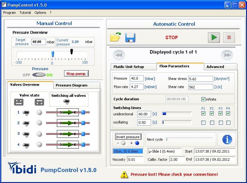
Table of contents

1.      General Information ........................................................................................................ 2
     1.1 System Requirements................................................................................................ 2
     1.2 Installation .................................................................................................................. 2
2.      Software PumpControl ................................................................................................... 3
     2.1 Manual Control ........................................................................................................... 3
       2.1.1 Setting the Output Pressure................................................................................. 4
       2.1.2 Valve Overview and Pressure Diagram Register .................................................. 5
     2.2 Automatic Control ...................................................................................................... 6
3.      Detailed Instructions of the “Automatic Control” ........................................................... 8
     3.1 Flow Parameters ........................................................................................................ 9
       3.1.1 Definition of Flow Rate, Shear Stress or Shear Rate ............................................ 9
       3.1.2 Cycle Duration .................................................................................................... 10
       3.1.3 Active Pump Ports ............................................................................................. 10
       3.1.4 Switching Times................................................................................................. 10
     3.2 Start the Scheduler (Automatic Control) ................................................................... 11
       3.2.1 Add More Cycles to Your Scheduler................................................................... 12
       3.2.2 Clear All Cycles .................................................................................................. 12
       3.2.3 Repeat All Cycles ............................................................................................... 13
       3.2.4 Cycle Creator ..................................................................................................... 14
     3.3 ibidi Experiment Builder ........................................................................................... 18
     3.4 Overview of the Actual Flow Settings and Experiment Status ................................. 21
     3.5 Recalibration of the Fluidic System .......................................................................... 22
       3.5.1 How to Run a Recalibration? .............................................................................. 22
4.      Control During an Active Scheduler .............................................................................. 26
     4.1 Working with the Pressure Diagram ......................................................................... 27
     4.2 Settings Summary / ‘i’nfo Box .................................................................................. 27
5.      PumpControl Navigation Bar ......................................................................................... 29
     5.1 Program ................................................................................................................... 29
       5.1.1 Program Options ................................................................................................ 29
       5.1.2 Open Current Log File… .................................................................................... 32
       5.1.3 Demo Mode ....................................................................................................... 32
       5.1.4 Exit ..................................................................................................................... 34
     5.2 Tutorial ..................................................................................................................... 34
       5.2.1 Load Demo Setups ............................................................................................ 34
       5.2.2 Movies ............................................................................................................... 35
     5.3 Options .................................................................................................................... 36
       5.3.1 Settings .............................................................................................................. 36
       5.3.2 Set Device Parameter… ..................................................................................... 36
       5.3.3 Manual ............................................................................................................... 36
       5.3.4 About… .............................................................................................................. 36
6.      Troubleshooting ............................................................................................................ 37
     6.1 Troubleshooting Using the Control LEDs .................................................................. 38

ibidi PumpControl                                         1                  Version 1.5.4, 27 February 2019       © ibidi GmbH 2019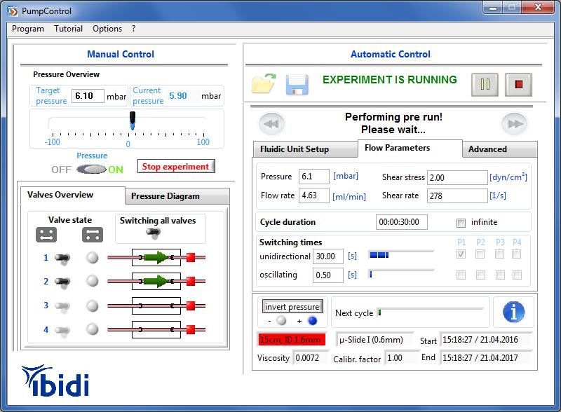
1. General Information
This software is designed to control the ibidi Pump. Other devices are not supported and the
program will only start in Demo Mode.
The ibidi PumpControl software controls the outgoing pressure [mbar] that will be applied to
the Fluidic Unit(s) and the switching operation of the valves. Shear stress and flow rate are
only a result of the outgoing pressure, and the Perfusion Set and µ-Slide. To learn more
about the relation between the pressure, and the flow rate, please refer to the ibidi Pump
System instructions.
1.1 System Requirements
In order to run PumpControl on a computer, the following components are required:
Operating System: Windows 7,Windows 8, Windows 10, 64-bit
Free USB-port
Hard disk space for PumpControl ca. 250MB
Working storage (RAM): min. 4 GB
Processor (CPU): min. Intel Pentium Dual Core
1.2 Installation
The installation package comes on a USB flash drive with your ibidi Pump Sytem or can be
downloaded from the ibidi website. Save the complete installer package on your computer
and follow these steps:
1. Log in as Administrator, if necessary.
2. If the software doesn’t start automatically, run ‘setup.exe’ and follow the setup
routine.
3. Setup the pump as described in the ibidi Pump System instructions. Connect the
pump to the computer via the USB-cable.
4. Restart the computer and start PumpControl.
5. Choose one of the options in the Fluidic Unit starter window (shown in Figure 1).
Figure 1 Fluidic Unit Starter window
Version 1.5.4, 27 February 2019 © ibidi GmbH 2019 2 ibidi PumpControl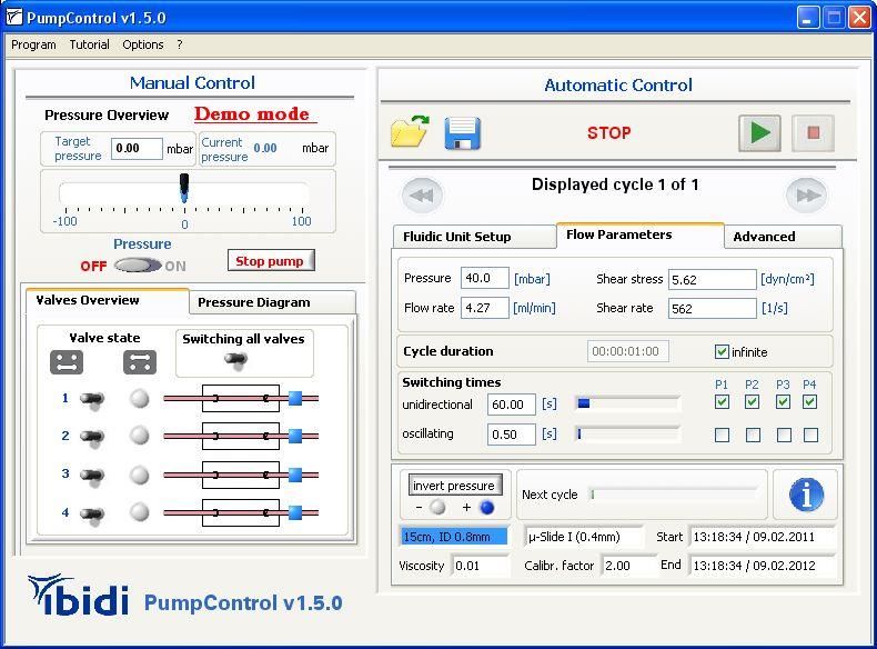
6. If the Pump is recognized by the computer, the main window opens in standard
operating mode (not in Demo mode!). If the Demo mode is activated (red text in
Figure 3), switch back to standard mode by clicking on the option “Demomode” in the
program menu (see Figure 2):
Figure 2 Changing from Demo mode to standard mode and back
Figure 3 Indication of the Demo mode in the main window
7. The program is now ready to control the operations of the ibidi Pump.
2. Software PumpControl
The PumpControl software controls the following parameters:
Air pressure (-100mbar….+100mbar)
Cycle duration (1s….infinite)
Switching intervals
Valve switching/valve state
Enables the setup of advanced assays with multiple cycles and loops
On the left side of the PumpControl window you can control those parameters separately by
hand (manual control). On the right side of the window, more complex setups with multiple
cycles and loops can be programmed (automatic control).
2.1 Manual Control
ibidi PumpControl 3 Version 1.5.4, 27 February 2019 © ibidi GmbH 2019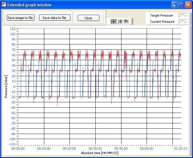
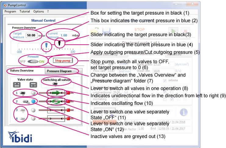
On the left side of the PumpControl panel, you’ll find all manual controls and displays for the
actual state of the pump, as shown in Figure 4. Manual controls are mainly used for
calibration and equilibrating of liquid levels.

Figure 4 Manual Control of the ibidi Pump with the control buttons on the left side of the PumpControl
software window.

 2.1.1 Setting the Output Pressure

Positive or negative pressure is set either by manually moving the black arrow (control 3 in
Figure 4), or by entering the pressure numerically (control 1). Values from -100 mbar to +
100 mbar are valid. The best results are achieved when working between 95 mbar and 5
mbar.

The “Pressure” button (control 5) indicates the state of the pump’s output pressure. By
clicking on this button, the pump switches between the two states:
    a) Pressure ‘OFF’ = the Fluidic Unit is connected to ambient air pressure. The liquid
        movement will be stopped, but the valves keep their positions and the target pressure
        is still shown in the box (control 1).
    b) Pressure ‘ON’ = the preset pressure is applied to the connected Fluidic Unit(s). The
        medium will be moved through the system.

The “Stop Pump” button (control 6) switches the pressure OFF, additionally resets all valve
states to their default positions and sets the target pressure to “0”.

Version 1.5.4, 27 February 2019   © ibidi GmbH 2019       4                            ibidi PumpControl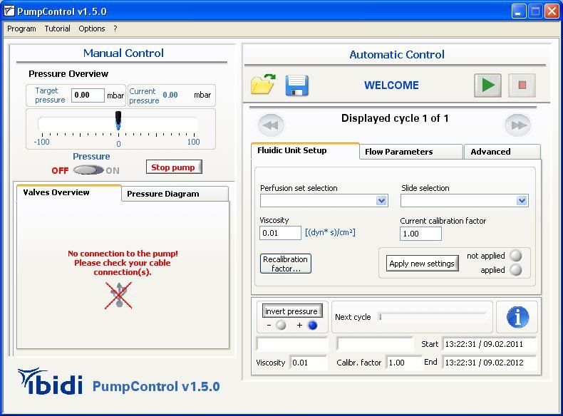
2.1.2 Valve Overview and Pressure Diagram Register
(a) (b)
Figure 5: (a) Valve overview and (b) Pressure Diagram
Control 7 in Figure 4 shows the position of the two registers, where you can switch between
“Valve Overview” and the “Pressure Diagram”.
2.1.2.1 Valves Overview
In this tab, you’ll find the state of all the connected Fluidic Units valves, and the actual flow
direction will be simultaneously indicated. There are 3 types of flow indications:
Unidirectional flow with positive pressure (from left to right)
Unidirectional flow with negative pressure (from right to left)
Oscillating flow
The valve controls (control 11 and 12 in Figure 4) can be switched individually. The two
states are shown below:
= Valve is in State 2 (Blue LED on pump is ON.)
= Valve is in State 1* (Blue LED on pump is OFF.)
*This is the default position.
There is also a master switch, which acts simultaneously on all active valves. When using
this control (8), all active valves will change their current state. Please note that depending
on the actual state, one valve might change from State 1 to State 2, while another might
switch from State 2 to State 1.
2.1.2.2 Pressure Diagram
In this tab, you’ll find a graph that illustrates the recorded course of the air pressure at the
pump output. Please note that this small graph only displays the last 5 recorded minutes of
your experiment. To view the whole process, you need to click on the graph, then a new
window will open. Please refer to section 4 to learn more about this.
Please keep in mind that the valves will only switch correctly if the tubing is inserted
properly. Please refer to the ibidi Pump System manual for correct tube handling.
ibidi PumpControl 5 Version 1.5.4, 27 February 2019 © ibidi GmbH 2019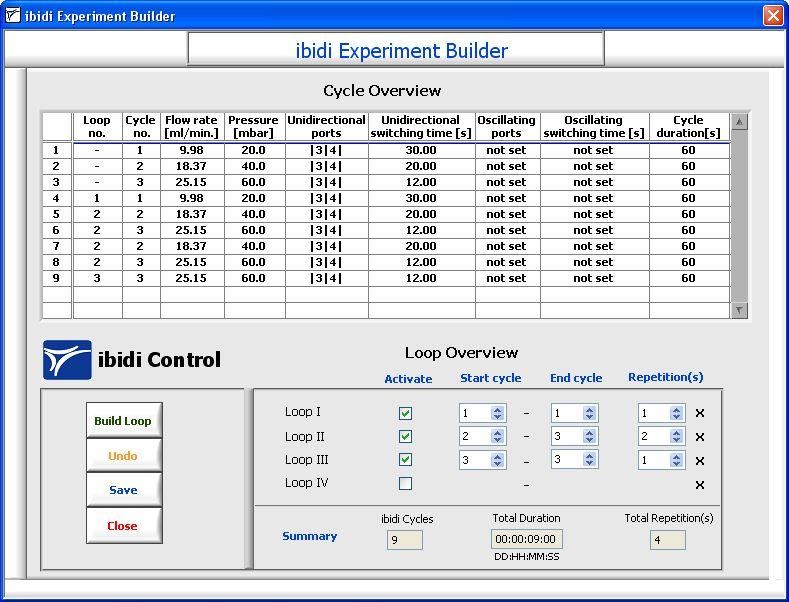
2.2 Automatic Control
The right side of the PumpControl panel is made for running automated flow assays. It’s
designed to make experiment setup easy.
The Automatic Control was developed to perform exact cycles over seconds, minutes, days,
or even weeks. With this tool, the shear stress that is applied to the cells in the µ-Slide can
either be set by choosing the air pressure, the flow rate, or the shear rate, or by directly
entering the shear stress. In any of these cases, the program will automatically calculate the
remaining values. Please note that the value of the viscosity has to be adapted to your
medium, in order to achieve a correct relation between the flow rate and the shear rate. The
next sections will explain the Automatic Control.
Symbols of the Automatic Control:
Starts the Scheduler with the current settings.
Pauses the Scheduler. Please note that the pressure will be switched
OFF to ensure that the medium inside the fluidic unit(s) does not move.
Stops the Scheduler immediately. All valves will be switched OFF and
the pump will stop.
Switches to the next cycle.
Switches to the previous cycle.
Version 1.5.4, 27 February 2019 © ibidi GmbH 2019 6 ibidi PumpControl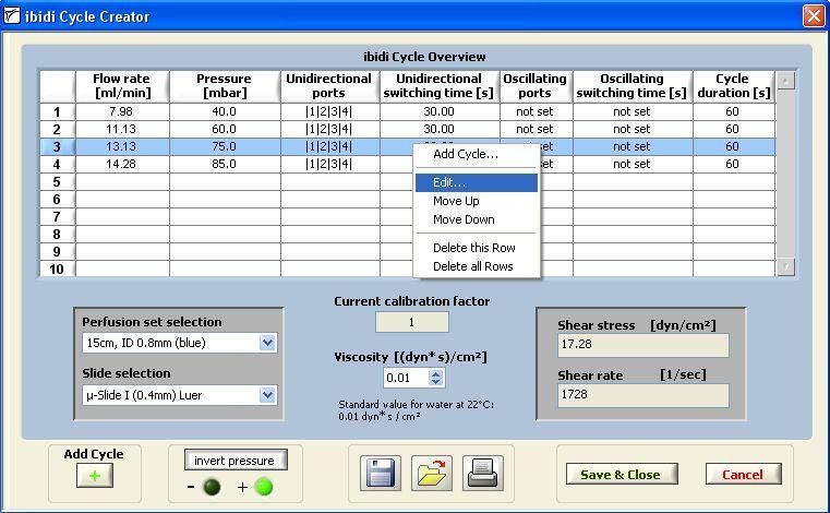
Displays the current settings of your experiment. Please note that this is
only a summary of your settings. Parameters cannot be changed.
Saves your cycle settings to a file (*.wof).
Loads a ‘*. wof’ file to your Scheduler. Please note that, not only the
‘Flow Settings’, but also the ‘Fluidic Unit Setup’, will automatically be
imported to the Scheduler.
Adds another cycle to the Scheduler.
Removes the current cycle from the Scheduler.
Removes all programmed cycles from the Scheduler.
Repeats all cycles. When you activate this button, you can select the
number of sequences. The maximum number is limited to 100.000.
The ‘Experiment Builder’ allows you to build loops from the defined
cycles.
In the ‘Cycle Creator’, the parameters of your settings can be changed
in a table overview.
ibidi PumpControl 7 Version 1.5.4, 27 February 2019 © ibidi GmbH 2019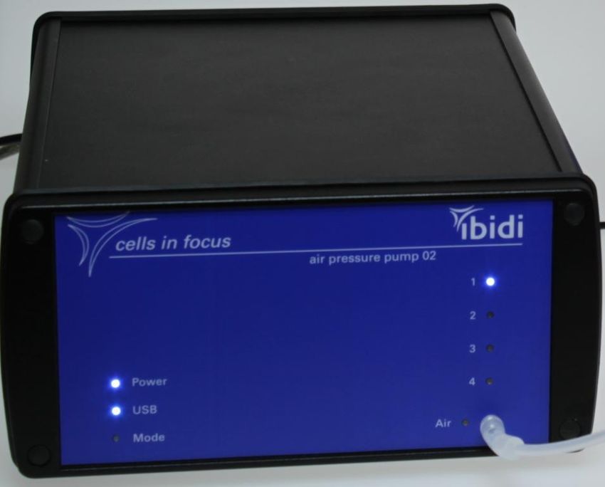
3. Detailed Instructions of the “Automatic Control”
With the Automatic Control functions of PumpControl you can create a schedule that has all
of the necessary settings, with just a few clicks.
The Automatic Control window consists of two sections: The one, where you can define your
parameters and the one, which shows you the actual settings.

                                                                      Input of parameters

                                                                      Actual settings overview

   Figure 6 Automatic Control panel

In the “Input”-section you will find three registers for defining the setup: “Fluidic Unit Setup”,
“Flow Parameters” and “Advanced”.

Figure 7 Three register tabs for defining the parameters

The ibidi Pump and PumpControl runs whether or not you define your Fluidic Unit setup.
However, if you want to make use of the automated calculation of the shear stress, or the
flow rate, you have to set the information about the viscosity of your medium, the selected
Perfusion Set (control 1 in Figure 8) and µ-Slide (control 2 in Figure 8) in the register tab
“Fluidic Unit Setup”.

Version 1.5.4, 27 February 2019   © ibidi GmbH 2019        8                         ibidi PumpControl
Figure 8: Fluidic Unit Setup
Please note: The “Apply new settings” button needs to be pressed after every change.
After entering your settings, you need to confirm the change by pressing the ‘Apply new
settings’ button (control 6 in Figure 8). If any parameters like µ-Slide, Perfusion Set, viscosity,
or the recalibration factor has been changed, the “Apply new settings” button will start
blinking. The blinking stops when these changes are confirmed. This will mean that the
software is now using this new set up for the internal calculations.
3.1 Flow Parameters
3.1.1 Definition of Flow Rate, Shear Stress or Shear Rate
After selecting the viscosity, Perfusion Set and µ-Slide, you can define the desired flow
parameters, such as the flow rate (control 1 in Figure 9), the shear stress (control 2), or the
shear rate (control 3). You can only define one parameter. The Scheduler will automatically
calculate the required pressure of your inputs. Please select the register tab ‘Flow
Parameters’ to choose these settings.
Insert your desired Insert your desired
flow for the current shear stress for the
cycle. (1) current cycle. (2)
Insert your desired
shear rate for the
current cycle. (3)
Insert the run time of the
cycle. The minimum of
this entry is 1 second. (4)
Figure 9: Flow Parameters
You can also insert a pressure amount and observe the changes in flow rate, shear stress,
and shear rate.
Please note that based on the calculated flow, the switching time will change. However, the
cycle time can still be modified manually after that calculation
ibidi PumpControl 9 Version 1.5.4, 27 February 2019 © ibidi GmbH 20193.1.2 Cycle Duration
The cycle duration defines the length of a cycle, with its defined flow parameters. Because
the cycle parameters also include the switching time, the cycle duration must be a multiple
whole number of the switching interval. The cycle duration has to be set for every cycle. You
can find the cycle duration in the respective box (control 4 in Figure 9). The unit for this
setting is [DD:HH:MM:SS]. If you wish to run the cycle in an endless loop, you need to check
the box ‘infinite’. Once the ‘infinite’ check box is active, the creation of additional cycles is no
longer available. Please note that only the last cycle has the option to be infinite.
Checking this button allows
the last cycle to run for an
unlimited amount of time.
3.1.3 Active Pump Ports
The software automatically detects all connected Fluidic Units (active pump ports). This can
be verified either by controlling the checked boxes, shown in Figure 10, control 3. It can also
be verified on the manual control panel, in the valve overview. Active valve switches (control
11-13 in Figure 4) are shown in full color, inactive valve switches are greyed out.
Active pump ports in
Switching time for unidirectional flow
unidirectional flow. (1) mode (3)
Switching time for Active pump ports for
oscillating flow. (2) oscillating flow mode
(4)
Figure 10: Switching Times and Active Pump Ports
3.1.4 Switching Times
There are two different switching times, unidirectional and oscillating. Which switching time
applies to the Fluidic Units can be controlled by checking the respective boxes (control 3 and
4 in Figure 10).
3.1.4.1 Unidirectional Switching Time
The unidirectional switching time is needed in every experiment, at least for one Fluidic Unit.
In order to prevent the reservoirs from running dry, the valves of the Fluidic Unit(s) need to
be switched before the liquid level reaches the bottom of the syringe. This time period is
depending on the flow rate and is called ‘switching time’.
After each switching operation, the flow direction of the medium in the reservoirs is inverted
(not in the slide!). In the standard case, this switching time is calculated from the flow rate. If
you want to define the switching time yourself, you can insert the value in the box. There are
three aspects to consider when choosing an appropriate switching time:
1. During the time interval, the reservoir must not run dry.
Version 1.5.4, 27 February 2019 © ibidi GmbH 2019 10 ibidi PumpControl2. The vertical height difference between the liquid levels in the reservoirs never should
not be too high, in order to prevent pressure variations due to the hydrostatic
pressure variations. This is important when working with low pressure (5 – 10 mbar).
3. Also, the switching time should not be too short, to ensure that fresh medium can be
brought to the cells.
If you change the switching time (unidirectional), make sure that the cycle duration is a
multiple of the switching time. Otherwise, a new window will open, as shown below.
The default setting keeps the exact cycle duration. This option will adjust the switching time.
The other setting keeps the exact switching time. When you choose this option, the cycle
duration will be adjusted.
3.1.4.2 Oscillating Switching Time
The PumpControl software also supports oscillating flow assays that can simulate turbulent
flow at the cell position. This type of experiment requires you to change your setup, and this
is described in the ibidi Pump instructions.
The master Fluidic Unit must be set in the unidirectional switching mode. Up to three Fluidic
Units can be run in the oscillating switching mode. The oscillating switching time does not
influence the inversion of flow in the reservoirs. This must be controlled by the unidirectional
switching time of the master Fluidic Unit.
3.2 Start the Scheduler (Automatic Control)
Before you start the Scheduler program, make sure the reservoirs contain the same
amount of liquid (e.g. 5 ml in 10 ml reservoirs, or 1 ml in 2 ml reservoirs).
If you’ve followed the previous instructions, you are ready to run your experiment.
By pressing the ‘Play’ button ( ), the automatic flow process will start. A pop-up window
will appear in the monitor. If you want to disable the function, uncheck the according
checkbox.
The ‘Play’ button will then change into a ‘Pause’ ( ), allowing you to pause the current
experiment at a specific point, and restart it later.
While the schedule is running, we recommend that you observe the liquid levels in the
reservoirs so that you can control the flow rate. If for any reason the flow is blocked, or the
Fluidic Unit doesn’t work properly, the reservoirs might run dry and/or the cells in the µ-Slide
might not be supplied with the medium. Please refer to the trouble shooting section 6 to solve
this problem.
ibidi PumpControl 11 Version 1.5.4, 27 February 2019 © ibidi GmbH 2019Advanced
Deleting all cycles. (3) Adding a cycle. (2)
Deleting a cycle. (1)
Repeat cycles. (4)
Figure 11: Adding and Deleting Cycles
3.2.1 Add More Cycles to Your Scheduler
By following steps 0 to 3.1.3, you have input all of the necessary information needed to set
up a cycle, and start an experiment. However, in some cases you might want to run
successive cycles, with different settings, to perform your experiment. For that, you can add
a cycle by clicking on the ‘Add cycle’ button (control 2 in Figure 11) on the register tab
‘Advanced’. Afterwards, you’ll have a copy of the first cycle that can be modified as described
in sections 0 to 3.1.3. You can add as many cycles as you need. To switch between the
cycles, you have to click on the ‘next cycle’ button, or the ‘previous cycle’ button, shown in
Figure 12, controls 1 and 2.
Go to previous cycle. (1) Go to next cycle. (2)
Figure 12: Switching Between Different Cycles
3.2.2 Clear All Cycles
On the register tab ‘Advanced’, you’ll find a button labelled ‘Clear all cycles’ (control 1 in
Figure 13). This function allows you to clear all programmed cycles at once.
Button ‘Clear all cycles’. (1)
Figure 13: Clear All Cycles
Version 1.5.4, 27 February 2019 © ibidi GmbH 2019 12 ibidi PumpControlFigure 14: Clear All Cycles Options
After clicking on this button, a safety query will pop up (see Figure 14). In this dialog box, you
can choose from three options:
1. To ‘Cancel’ you will return to your main program.
2. To ‘Save’ you will save all current cycle definition sets into a file.
3. To ‘Clear’ all your cycle definition sets will be deleted.
3.2.3 Repeat All Cycles
If you want to repeat one cycle, or a series of cycles, you can build loops. For this action,
you’ll find a button in the ‘Advanced’ tab, labelled ’Repeat all cycles’ (control 4 in Figure 11).
By activating this button, you can choose the number of sequences you’d like to run from the
set of cycles you’ve already created.
Figure 15: Set of Cycles
In the example below, you have previously created three cycles, as shown in Figure 15. If
you decide to ‘Repeat all cycles’ six times, as indicated in Figure 6, you will end up running
18 cycles, in the order of 1 2 3 1 2 3, and so on.
repeat
ibidi PumpControl 13 Version 1.5.4, 27 February 2019 © ibidi GmbH 2019Open the ‘Cycle Creator’.
Figure 16: Set of Cycle in the 'Cycle Creator' Table
If you want to check the status of your experiment, you can always open the ‘i’nformation box
(control 2 in Figure 29 on page 26) to see how many sequences have been generated, and
which cycle is currently being executed. This overview function is described in more detail in
section 4.2.
3.2.4 Cycle Creator
The ‘Cycle Creator’ function is designed to help create sets of cycles without having to click
through the different register tabs. Once you’ve entered the ‘Cycle Creator’, a table will
appear and you will be prompted to enter the following parameters for the ibidi Pump, and
the connected Fluidic Unit(s):
1. The flow rate, which will result in a certain air pressure
2. the cycle duration,
3. the active pump ports, and also
4. the switching time of the individual cycle.
You can also modify the ‘Fluidic Unit Setup’, for example the Perfusion Set and µ-Slide.
These parameters will be valid for all cycles that are being created.
The ‘Cycle Creator’ will automatically list all of the cycles that are currently programmed into
the PumpControl session.
In Figure 16, you can see an example of some entries in the ‘Cycle Creator’ function.
To run an experiment, you need to define at least one cycle. However, you can create an
experiment containing 100 cycles or more; each of them can, and most likely, will have
different flow settings.
Version 1.5.4, 27 February 2019 © ibidi GmbH 2019 14 ibidi PumpControlExample:
Your cells need to be adapted to specific flow conditions. We recommend starting with a low
flow rate and then increasing the shear stress over time.
First Cycle: Low flow for 30 minutes and a shear stress of 2 dyn/cm².
Second Cycle: Shear stress of 5 dyn/cm² and cycle duration of 30 minutes.
Third Cycle: Long cycle duration of 3 days and final shear stress of 10 dyn/cm².
These different flow rates can be realized by defining the three cycles. Afterwards, you can
still change the order of the list, which will then become the order for the schedule.
Add a Cycle to Your Overview
To create a new cycle, you can either right-click in the list and choose ‘Add Cycle…’, or press
the ‘Add Cycle’ button, as shown in Figure 17.
Add a cycle to your overview.
Figure 17: Create a New Cycle
A new dialog box will open where all the required parameters can be set (see picture below,
‘Cycle settings’). If you have more than one Fluidic Unit, you are able to select between
unidirectional and oscillating flow. For more details, please refer to the ibidi Pump manual.
ibidi PumpControl 15 Version 1.5.4, 27 February 2019 © ibidi GmbH 2019Once the ‘Cycle settings’ window is open, the following
parameters can be entered:
1. Pressure
2. Flow rate
3. Shear stress
4. Shear rate
5. Cycle duration
6. Pump ports (P1- P4)
7. Switching times
Please note that, depending on the flow rate, the cycle time of the unidirectional switched
valves will be internally recalculated. You will still be able to manually modify this value.
After confirming your selection with the ‘OK’ button, the cycle is added to the overview.
3.2.4.1 Modifying Cycles
By right clicking on a row that has an existing cycle set in the table, you can modify the
entries, as shown in Figure 18. Here are the following options:
Figure 18: Modifying Entries in the 'Cycle Creator'
Add another cycle to the list of cycles ‘Add cycle…’
Edit the cycle ‘Edit…’
Move a cycle up or down ‘move up’ / ‘move down’
Delete a cycle ‘Delete this row’
Delete all cycles ‘Delete all rows’
Version 1.5.4, 27 February 2019 © ibidi GmbH 2019 16 ibidi PumpControlIf you choose to edit a cycle, the ‘Cycle settings’ dialog box will appear:
3.2.4.2 Additional Functions
The ‘Cycle Creator’ includes most of the functions available in the PumpControl main menu.
Figure 19 shows the overview with a brief description.
Saves the cycle list overview. Loads the settings file
Please note that all (*.wof), including the
information will be saved in ‘Cycle Creator’ entries.
this file.
Button to print the ‘Cycle
Creator’ Overview.
Figure 19: Functions within Cycle Creator
Defines either positive or
negative outgoing pressure.
ibidi PumpControl 17 Version 1.5.4, 27 February 2019 © ibidi GmbH 20193.3 ibidi Experiment Builder
In addition to the Cycle Creator, we offer a
function called the ‘Experiment Builder’. Activates the
With this tool, you can insert loops into your ‘Experiment Builder’.
cycle schedule. You can loop any cycle you
have already programmed into the Cycle
overview.
Before you start the ibidi ‘Experiment Builder’, you need to have created at least one
complete cycle set. If you want to use more than one set, you should first arrange your list in
the desired order. This is done because all cycles are initially executed once (e.g. if you have
3 cycle sets, as shown in Figure 20, you will always start your experiment by executing
cycles 1 to 3, before starting the first loop).
Once you have arranged your cycle list, you can click on the ‘Experiment Builder’ button, as
illustrated above. A new window will open and all the programmed cycles will appear in the
‘Cycle Overview’ table, as shown in Figure 20.
Cycles within
the loop. (2)
Activation of loops. (1)
Repetition
index. (3)
Experiment
duration. (5)
Total number
of cycles. (4)
Total number of
Figure 20: Experiment Builder repetition(s). (6)
There are several functions shown in this window:
1. Activate up to four loops (Loop I IV) (control 1, in Figure 20).
2. Choose the start and the end cycle (control 2).
3. Choose the number of runs per loop (control 3).
Version 1.5.4, 27 February 2019 © ibidi GmbH 2019 18 ibidi PumpControl4. Transfer the loop content to the Cycle overview by pressing the ‘Build Loop’
button.
5. Undo this operation with the ‘Undo’ button.
6. Store the new cycle list so that the cycles will be executed by pressing the
‘Save’ button.
7. Afterwards, you can close the window with the button ‘Close’.
Additionally, you’ll find the indicators 4 and 5, as shown in Figure 20. These show the total
number of cycles of your experiment, and also the total duration. Indicator 6 displays the
repetition(s) of the loops.
Example:
Step 1-3:
3 loops are activated.
Start and end cycles are entered.
The number of repetition(s) is selected.
Figure 21: Experiment Builder Steps 1-3
ibidi PumpControl 19 Version 1.5.4, 27 February 2019 © ibidi GmbH 2019Step 4:
The loops are transferred to the Cycle Overview list with the ‘Build Loop’ button.
Please note: the individually programmed cycles from the main menu of PumpControl will
always appear, and be executed, one time at the beginning of the experiment. These cycles
are characterized with (-) and are called the ‘basic cycles’.
Figure 22: Experiment Builder Step 4
Step 5:
It is possible to erase the created cycle loop list.
When you press the ‘Undo’ button, all loops in the Cycle Overview will be erased.
After this, you can create new loops.
Step 6:
When you press the ‘Save’ button, after Steps 1-4, the new cycle list will be
transferred to the main PumpControl menu. You can view the cycle list in the Cycle
Overview table (see Figure 23) or by selecting the information box, as shown in
section 4.2 (control 2 in Figure 25).
Version 1.5.4, 27 February 2019 © ibidi GmbH 2019 20 ibidi PumpControlBasic cycles
Loop I
Loop II
Loop III
Figure 23: Cycle Table of the Built Cycles
Step 7:
You can exit your ibidi ‘Experiment Builder’ by pressing the ‘Close’ button. Once
you’ve successfully exited this operation, you’ll see the message shown below in
Figure 19.
Figure 24: Loops Main Menu Information
3.4 Overview of the Actual Flow Settings and Experiment Status
At the bottom of the ‘Automatic Control’ panel, in Fehler! Verweisquelle konnte nicht
gefunden werden., you’ll find the overview and information sections like indicated in Figure
25.
In the middle of Figure 25, you’ll find the horizontal progress bar, indicating the start of the
next cycle. On the lower right-hand side, the experiment start and finishing times are shown.
Next to this, the ‘Fluidic Unit Setup’ is displayed and shows the selected µ-Slide, the
Perfusion Set, the viscosity, and the calibration factor.
In this panel, you’ll also find two functional buttons: ‘invert pressure’ and ‘i’nformation. With
the ‘invert pressure’ button (control 1 in Figure 25), you can invert the airflow by switching
between the positive and negative air pressure. Activating the ‘i’nformation button (control 2
in Figure 25), allows you to reach an overview table that lists the cycles you’ve created. In
that menu, the active cycle is highlighted. More details can be found in section 4.2.
Opens the ‘info
box’. (2)
Invert pressure function. (1)
Figure 25: Overview and Information
ibidi PumpControl 21 Version 1.5.4, 27 February 2019 © ibidi GmbH 20193.5 Recalibration of the Fluidic System
Recalibration of the Fluidic System
As previously explained, PumpControl automatically calculates the flow rate and the shear
stress from a given air pressure. This is achieved by internal calibration tables. For most
applications, the automatically generated values are sufficient. However, you have to keep in
mind that the calibration conditions (using distilled water at 20 °C) might differ too much from
you own settings. In this case, it is necessary to calibrate your system in order to correct your
specific pressure-flow relation. Calibration is easily done using the ‘Recalibration factor …’
function. We recommend calibrating your system each time you change your setup,
especially when you rely on very precise shear stress values. Recalibration is also needed
when you observe a strong deviation from the expected flow rate.
This function is reached by clicking on the ‘Recalibration factor…’ button, after which the
‘Recalibration dialog’ box will appear (see Figure 26).
Current calibration factor. (1)
Figure 26: Recalibration Factor
The current calibration factor is indicated in the register tab as control (1) in Figure 26. The
default value is 1.00 (for water at 20°C).
3.5.1 How to Run a Recalibration?
Below, you will find an example of a recalibration. Please follow the next steps to perform
your own calibration:
Step1:
Create a complete cycle, including the ‘Fluidic Unit Setup’ and the ‘Flow Parameters’,
as shown in the figure above.
Set up a perfusion experiment without any air bubbles. Use the same condition
(tubing, µ-Slide, medium and temperature) as will be used for your experiment.
Equilibrate the reservoirs.
Version 1.5.4, 27 February 2019 © ibidi GmbH 2019 22 ibidi PumpControlStep 2:
Measure the time the medium takes to flow 2 ml. If you filled the reservoirs with 10 ml
of medium and equilibrated it at around 5 ml, we recommend measuring the time the
medium needs to run from 4 ml to 6 ml. It is sufficient to use the markers on the
reservoirs to achieve the accuracy of the system.
Now you can calculate the flow by inserting the time you measured into the formula below:
sec
2ml 60
ml min
min t sec
Step 3:
Now you can use this value to update the PumpControl software in the ‘Recalibration
factor…’ menu. To do so, click on the ‘Recalibration factor…’ button and insert the
preset flow rate (control 1 in Figure 27) and also the measured one (control 2). You
will end up with a new calibration factor (indicator 3, in Figure 27), which will correct
the flow rate, the shear stress, and the shear rate.
Present flow rate. (1) New calibration factor. (3)
Measured flow rate. (2)
Figure 27 Recalibration Dialog
ibidi PumpControl 23 Version 1.5.4, 27 February 2019 © ibidi GmbH 2019Explanation of the ‘Recalibration dialog’ window:
The default value for the ‘Given flow rate’ is 1.00 ml/min. This value has to be set to
the expected value.
Initially, the ‘previous calibration factor’ is the default value, or your ‘current calibration
factor’. Please note that if you have calibrated your system before, and you have
already changed the calibration factor, this value will differ from the default.
The ‘current calibration factor’ is the ratio from the ‘Given flow rate’ to ‘Measured flow
rate’. In our example it is ‘2’.
The ‘resulting calibration factor’ is the product of the ‘previous calibration factor’ and
the ‘current calibration factor’. Here it is also ‘2’. Again, if you had a ‘previous
calibration factor’ that is not ‘1’, the ‘resulting calibration factor’ is:
(resulting calibration factor) = (previous calibration factor) × (current calibration factor)
With this method, we can account for the previous calibrations, and you are able to
iteratively find your optimal calibration. Normally, only one calibration operation is
necessary, due to the precision of the system.
When you now confirm your new calibration, by clicking on the ‘Update’ button, the window
closes and the ‘resulting calibration factor’ will automatically be set as your ‘Current
recalibration factor’.
Next, you need to accept the new settings by pressing the blinking ‘Apply new settings’
button. Afterwards, this value is stored in the system. In our example, you will find this as
Calibr. Factor = 2.00 in Figure 28.
Actual settings
overview.
Figure 28 Applied Settings
Version 1.5.4, 27 February 2019 © ibidi GmbH 2019 24 ibidi PumpControlOnce the ‘Current recalibration factor’ has been changed, the air pressure will be adapted. The pressure is the only parameter that will be modified, as shown in the figure below: If you want to undo your manual calibration, you can use the ‘Reset’ button in the ‘Recalibration dialog’ window and confirm with the ‘Update’ button. This will restore the default values in the system. ibidi PumpControl 25 Version 1.5.4, 27 February 2019 © ibidi GmbH 2019
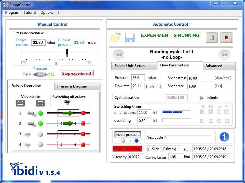
4. Control During an Active Scheduler
While the Scheduler is running, the functions are limited in the ibidi Pump. Most importantly,
you can still stop the pump immediately by clicking on the ‘Stop’ button (controls 1 and 2 in
Figure 29). You can also find several indicators (3) to (8) that display the current status of the
experiment, as seen in the figure below.

                                                           Scheduler status (WELCOME,                Pump
                                                           EXPERIMENT IS RUNNING,                    stop. (2)
                                                           BREAK, STOP). (3)

                                    Stop experiment. (1)

                                                                                              Executed
                                                                                              cycle. (4)

                                                                                            Cycle
                                                                                            information. (5)

                                                                                   Start and end
                                                           Settings of the         time of the
                                                           experiment. (7)         experiment. (6)
                    Pressure diagram of
                    the last 5 minutes. (8)

Figure 29: Pump Control During the Course of the Experiment

Pre- and Post-Run

In order to have the liquid levels in the reservoirs equilibrated, PumpControl performs a pre-
and post-run at the beginning and end of each cycle. These two runs apply the same
conditions to the Fluidic Unit with only half of the switching time. As a result, the minima and
maxima of the liquid levels in both reservoirs should be the same.

Version 1.5.4, 27 February 2019   © ibidi GmbH 2019         26                          ibidi PumpControl
Please note that the ibidi Pump has no feedback loop for the liquid levels. Therefore, we
recommend checking them after starting the experiment, so that the reservoirs don’t run
dry.
4.1 Working with the Pressure Diagram
The small graph, on the left side of PumpControl menu, only shows the course of the last 5
minutes of your experiment. To see the entire recorded data of your experiment, click on the
small diagram to extend the graph (see Figure 30).
Change the view
by zooming into
the graph, or by
moving it.
Save the entire
graph to a bitmap
file (.bmp).
Save data as an ascii file with
the extension ’.data’ .
Figure 30: Extended Graph Window
In the ‘Extended graph’ window, you have the opportunity to work with the data:
You can save the graph into a bitmap or as ascii file. You can also zoom in and out of
the graph.
4.2 Settings Summary / Info Box
The ‘i’nfo button (control 5, in Figure 29) can be opened at any time to view a summary of the
Scheduler’s current status. This might be useful during longer experiments, to see which
cycle and cycle parameters are being executed.
ibidi PumpControl 27 Version 1.5.4, 27 February 2019 © ibidi GmbH 2019Indication of current
cycle.
Indicator for the
number of sequences.
Indicator for the applied shear stress
and shear rate of the marked cycle.
Figure 31: Settings Summary
In the above table, you will find all of the flow parameters:
Flow rate
Air pressure
Pump ports for unidirectional or oscillating flow
Switching time for unidirectional or oscillating flow, and
the cycle duration
Below the table, you’ll see the setup of your experiment:
Selected µ-Slide
Selected Perfusion Set
Viscosity, and
Calibration factor
If you select a cycle from the list, you will find two indicators displaying:
Shear stress, and
Shear rate
You can also find the number of stored cycles and the cycle currently being executed.
Additionally, the number of outstanding sequences is also displayed.
Version 1.5.4, 27 February 2019 © ibidi GmbH 2019 28 ibidi PumpControl5. PumpControl Navigation Bar
1 2 3 4
The four different points are described in the following sections.
5.1 Program
5.1.1 Program Options
To modify the settings for PumpControl, go to ‘Program’ in the navigation bar and select
‘Program options…’, or use the shortcut ‘Strg’+’O’.
5.1.1.1 General
PumpControl gives you the opportunity to log the data and parameters of your experiment.
This can be useful in reproducing any expected, but also the unwanted effects which
occurred during your experiment. This data can help you debug a failed experiment. You can
turn the logging setting to ON or OFF and also set the recording interval (see Figure 32).
Recording
interval
Enable or disable the
data logging
Figure 32: Program Options
The path of your log file, and all other paths, can be set in the register tab ‘Program Paths’
(see section 0). By default, the log files are stored in ‘c:\documents and settings\[user]\[user
files]\ PumpControl v1.5.0\log’. Log files are text files (.txt) that can be viewed with any text
program (‘notepad’, ‘WordPad’, etc…).
The log file contains all the information about the state of the ibidi Pump. It is composed of
the following elements:
ibidi PumpControl 29 Version 1.5.4, 27 February 2019 © ibidi GmbH 2019Time Target Pressure Current Pressure Act. Valves Pressure on/off Date + Time 55.5 mbar 55.4 mbar 1|2| ON The time stamp of The target The output Active pump ports / Pump status: the logged data. pressure. pressure. Connected Fluidic Units. Pressure On/Off. The current log file can also be opened by selecting ‘Program’ ‘Open current log file…’, or by using the shortcut ‘Strg’+’L’. The screenshot below shows you an extract of the log file. 5.1.1.2 Alarm Settings PumpControl offers an alarm function, with an optical and acoustical warning, if the pump should lose pressure below a certain threshold. This warning is also included in the log file. This feature can be very useful for finding out when, and why, the experiment did not finish as expected. Version 1.5.4, 27 February 2019 © ibidi GmbH 2019 30 ibidi PumpControl
Enable or disable the alarm signal.
Define the threshold for the alert. For
example, if you choose 50% and your target
pressure is 60 mbar, the warning will occur
when the current pressure is below 30 mbar.
Define the wait time before
the warning signal occurs.
Example:
Target pressure (+60 mbar) not
reached for 10 seconds while the
pressure is on (ON).
Warning signal occurs.
Acoustical
signal from PC-
speaker
Optical pressure lost warning.
The most common problem is a communication failure between PC and pump:
‘No connection to the pump!’ Please check your cable connection(s).
ibidi PumpControl 31 Version 1.5.4, 27 February 2019 © ibidi GmbH 20195.1.1.3 Program Paths
The third register tab, in ‘Program Options’, is ‘program paths’. Here you’ll find the four paths
where different types of files are stored.
You can change the
directory.
The following files are found under these paths:
Data
o Calibration files
o Instructions
o Movies for the PumpControl v1.5.0
o USB driver
o Software driver
Log files
o Log files, as described in section 5.1.1.1.
Report files
o Graphical recording of the preset and the output pressure, as described in
section 4 on page 26.
Firmware
o This path is currently unused.
5.1.2 Open Current Log File…
Please refer to section 5.1.1.1 on page 29 (General).
5.1.3 Demo Mode
You can also use the PumpControl software, even if the pump is not connected to the
computer. In this case, the software starts in ‘Demo mode’.
Version 1.5.4, 27 February 2019 © ibidi GmbH 2019 32 ibidi PumpControlWhen the program is in ‘Demo mode’, there is no communication with the pump. This usually
happens when the USB cable is not connected between the devices (PC pump). If you
unclick ‘Demo mode’, you might see a message as shown in Figure 33.
‘No connection to the pump!’ Please check your cable connection(s).
Figure 33: Failing Connetion to the Pump
Please do not use the ‘Demo mode’ when you perform a cell experiment.
ibidi PumpControl 33 Version 1.5.4, 27 February 2019 © ibidi GmbH 20195.1.4 Exit
Close PumpControl and save all important parameters.
5.2 Tutorial
5.2.1 Load Demo Setups
5.2.1.1 Demo Experiment
To get started using PumpControl v1.5.0, we’ve created a tutorial program called ‘Demo
Experiment’. It shows you some of the typical settings in a sample experiment.
You can access this tutorial by selecting ‘Tutorial’ ‘Load demo setups’ from the menu bar.
There, you have the option to load an ibidi demo file. In this file, all cycles are defined and
you can immediately start the demo experiment.
Before the settings are applied to the system, the ‘Fluidic Unit’ is initialized.
Figure 34: Demo Experiment
Please make sure that if you use this option, you’ve already installed the red Perfusion
Set with the µ-Slide I (0.6mm), as shown in Figure 34.
For a detailed description, please see Application Note 13 ‘ECs under Perfusion’.
Version 1.5.4, 27 February 2019 © ibidi GmbH 2019 34 ibidi PumpControl5.2.1.2 Remove Air Bubbles
If you find air bubbles in the tubes and/or in the µ-Slide you can remove them by running a
flow through the Perfusion Set. You can do this by selecting ‘Tutorial’ ‘Load demo setups’
‘Remove air bubbles’ from the menu bar. There is a defined cycle in this file that creates
an appropriate flow through the system to remove the bubbles.
Please make sure that if you use this option you have installed the red Perfusion Set with
the middle connector, as shown in Figure 35.
Please be careful that you are not using slides with seeded cells, as they might be washed
out.
For a detailed description, please see Application Note 13 ‘ECs under Perfusion’.
Figure 35 Air Bubble Removal Settings
5.2.2 Movies
In the PumpControl tutorial, you will find a library, containing some movies that show how to
use PumpControl v1.5.0. They are applicable for version 1.5.4 as well. If you select ‘Tutorial’
‘Movies’ you can find a list of movies about the basic and advanced functions.
ibidi PumpControl 35 Version 1.5.4, 27 February 2019 © ibidi GmbH 20195.3 Options
5.3.1 Settings
Under the menu option, you can find four settings that relate to the following functions in the
program.
Fluidic Unit Starter
Equilibrated dialog
Software update
Firmware update
Here, you can enable or disable the ‘Fluidic Unit Starter’ and the ‘Equilibrated dialog’. You
can also check for PumpControl software and firmware updates. For the last two options, you
must ensure that your computer is connected to the Internet.
5.3.2 Set Device Parameter…
In the ‘Options’ section of the menu bar, you’ll also find a selection called ‘Set device
parameter…’. This function is for the manufacturer only. If you encounter any problems with
the ibidi Pump, or with PumpControl, please contact info@ibidi.de.
5.3.3 Manual
You can open the PumpControl instruction manual with this menu option.
5.3.4 About…
In this window, you can find information about the ibidi Pump.
Version 1.5.4, 27 February 2019 © ibidi GmbH 2019 36 ibidi PumpControl6. Troubleshooting
If you encounter any problems with the ibidi Pump System, please check the table
below for some troubleshooting solutions:
Problem Possible Solution
o No output pressure The pressure button is OFF.
o No continuous flow in the The Perfusion Set is not mounted correctly. Refer to the
µ-Slide. ibidi Pump instruction manual for further instructions.
Make sure all electrical connections are plugged in
properly. Wait a few seconds and try again. Make sure
o No connection to the pump.
that all drivers are properly installed, then Restart
PumpControl.
Sometimes the pump needs an internal restart. To do
o Error message occurs. that, disconnect the power cable and reconnect it
afterwards to restart the pump manually.
In this case you need set the ‘Data path’.
In the pump control menu, click on program options
program path data (see section 0). On the menu’s right
side, there’s a button for selecting the folder. Choose the
o Calibration file not found.
right path, (by default, PumpControl is installed in
C:\programs\PumpControl v.1.5.x\data), then restart
PumpControl. If the problem still remains, please contact
us at: info@ibidi.de
Please check if the Perfusion Set is correctly mounted.
Refer to the ibidi Pump instruction manual for further
o Reservoirs running dry. explanations.
If the flow rate is not as expected, please recalibrate the
system (refer to section 3.5 and follow the instructions).
Please make sure that the Perfusion Set is mounted
o Valves are not switching.
correctly.
It’s possible that the .NET framework software is not yet
o No communication between installed on your PC. In this case, you’ll need to install the
PC and pump. driver for the software. (see section 1.2. installation
point 5 Software driver.)
ibidi PumpControl 37 Version 1.5.4, 27 February 2019 © ibidi GmbH 20196.1 Troubleshooting Using the Control LEDs
Control LEDs on the Pump:
Valve state LEDs
Power LED
USB LED
Mode LED
Air LED
Power LED
The ‘Power’ LED is on when you connect the power supply.
USB LED
The ‘USB’ LED is on when you connect the pump to the PC with a USB cable, and when the
USB drivers are installed. If the drivers are not installed, the light will remain OFF.
To install the USB drivers manually, you need to go to the Windows start menu and choose
‘Programs’ PumpControl v1.5.0’ ‘USB Driver’, as indicated below.
Please press ‘USB Driver’ and the system will automatically install the drivers.
Afterwards, the USB light should be illuminated.
Version 1.5.4, 27 February 2019 © ibidi GmbH 2019 38 ibidi PumpControlMode LED
When the ‘Mode’ LED is blinking, the firmware is initializing. The LED is blinking when the
pump is connected to the power supply system. The blinking lasts for approximately 5
seconds.
Valve State LEDs
There are four LEDs on the pump to indicate which Fluidic Unit is being switched.
The software is using the same indicators.
Valve State Indicators and
Controls.
Air LED
The ‘Air’ LED is illuminated when there is pressure at the outlet.
Pressure ON LED ON.
Pressure OFF LED OFF.
Please contact us for further troubleshooting questions, and to report any bugs you find to
info@ibidi.com
ibidi PumpControl 39 Version 1.5.4, 27 February 2019 © ibidi GmbH 2019You can also read