Quick Start Guide WP120 Electric Water Pump - Engineered ...
←
→
Page content transcription
If your browser does not render page correctly, please read the page content below
Quick Start Guide
                           WP120 Electric Water Pump

                                 This manual is effective for consumer installations
                                 of EMP WP120 water pumps. OEM installers must
                                     contact EMP for production requirements.

        Rev    Rev By        Date                 Description of Change                Approved By
         A      ME          5/17/21     New Release                                     ECN6212

9970137016 Rev. A – 05/17/2021                     © 2021 EMP Inc.                                   1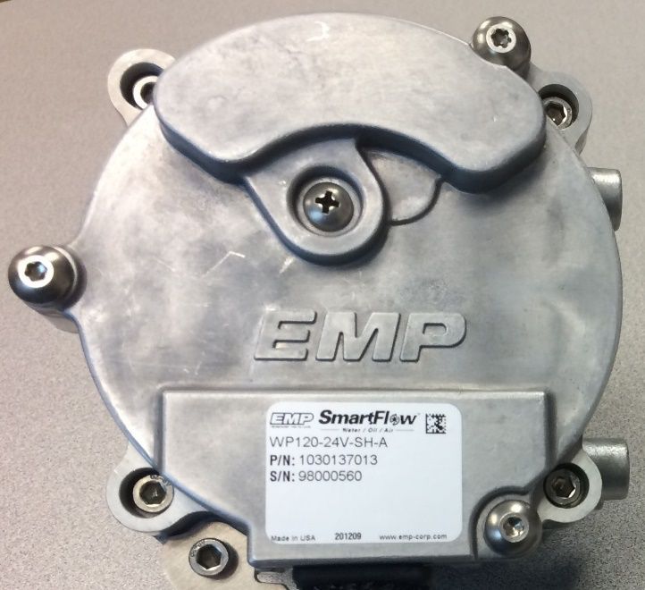
Product Overview
Engineered Machined Products, Inc.
2701 North 30th Street
Escanaba, MI, USA 49829
Phone: +1 (906) 789-7497
www.emp-corp.com
Service@emp-corp.com
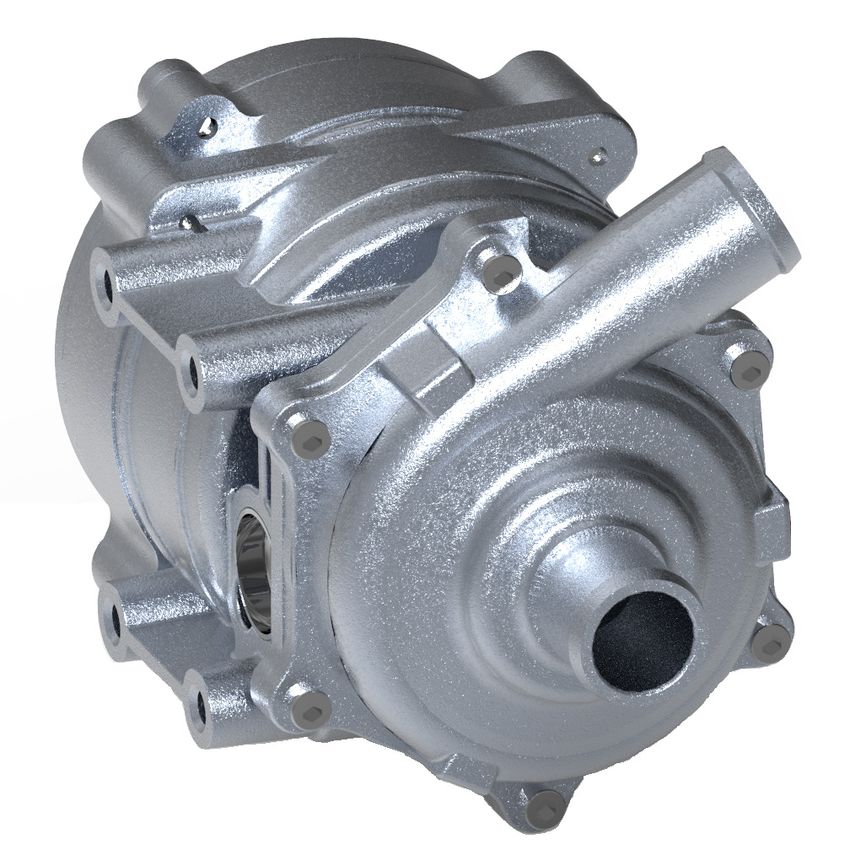
Product Overview
The WP120 is an electrically powered fluid pump available in 12 volt DC and 24 volt DC configurations. The
pump uses a stainless-steel shaft for fluid compatibility. Proper installation of the pump will help ensure the
performance and reliability of the electric pump while reducing the risk of damage to other components in the
system.
The information contained in this manual is updated periodically. While great care is taken in compiling the information contained in this manual, Engineered
Machined Products, Inc. cannot assume liability for losses of any nature arising from any errors and/or omissions.
The information and specifications contained throughout this manual are up to date at the time of publication. Engineered Machined Products, Inc. reserves
the right to change the content of this manual at any time without notice.
© 2021 EMP, Inc. 2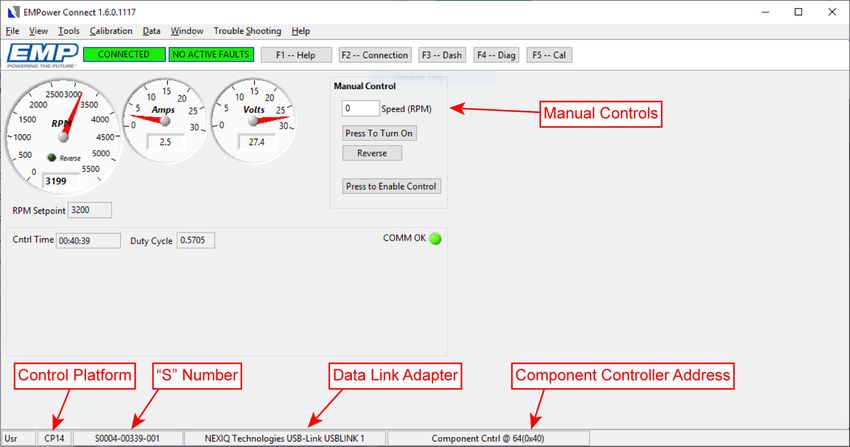
Table of Contents
Table of Contents
Product Overview .............................................................................................................................................. 2
Introduction........................................................................................................................................................ 4
   Purpose ......................................................................................................................................................... 4
   Service Technician Responsibilities ............................................................................................................... 4
   Liability Disclaimer ......................................................................................................................................... 4
   Additional Information .................................................................................................................................... 4
   Technical Help ............................................................................................................................................... 4
   Warnings, Cautions and Notes ....................................................................................................................... 4
   Definition of Terms ......................................................................................................................................... 4
Product Safety Warnings ................................................................................................................................... 5
Specifications .................................................................................................................................................... 6
   Dimensions and Hole Locations/Bolt Spacing ................................................................................................ 6
   Material Listing of Major External and Fluid Contacting Parts......................................................................... 7
   Operating Limits ............................................................................................................................................. 7
Identification ...................................................................................................................................................... 8
   EMP Water Pump Model Codes..................................................................................................................... 9
Installation ....................................................................................................................................................... 10
   Environment ................................................................................................................................................. 10
   Orientation ................................................................................................................................................... 10
   Plumbing ...................................................................................................................................................... 10
   System Fill Procedure .................................................................................................................................. 11
   Wiring........................................................................................................................................................... 12
   Electrical Connections.................................................................................................................................. 12
   10-way Component Connector ..................................................................................................................... 12
   10-way Mating Connector ............................................................................................................................ 12
   10-way On/Off Single Speed Control ........................................................................................................... 13
   7-way Component Connector....................................................................................................................... 14
   7-way Connector Greasing........................................................................................................................... 14
   7-way Mating Connector .............................................................................................................................. 14
   7-way On/Off Single Speed Control ............................................................................................................. 15
Routine Maintenance ....................................................................................................................................... 16
   Physical Inspection ...................................................................................................................................... 16
EMPower Connect™ Service Tool .................................................................................................................. 17
   Diagnostic Outputs (WP120) ........................................................................................................................ 17
   Diagnostic Outputs (WP120L) ...................................................................................................................... 17
Troubleshooting ............................................................................................................................................... 18

                                                                         © 2021 EMP Inc.                                                                             3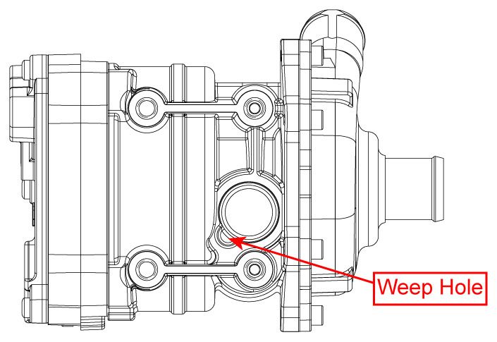
Introduction
Introduction
Purpose
The purpose of this quick start guide is to present information related to the pump’s dimensions, electrical
specifications, coolant guidelines, recommended plumbing, mounting orientation, and routine maintenance.

NOTE: For production applications of this product, the full installation specifications must be met. Contact
EMP to request documentation.

Service Technician Responsibilities
Ensure that all safety messages and information messages are read and understood before installation,
maintenance, or repairs are performed. It is important to use caution when service work is performed. Knowledge
of impacted systems and their operation are important before the removal or disassembly of any component.

Liability Disclaimer
EMP cannot anticipate every possible circumstance that might involve a potential hazard. The safety messages
in this document, in related manuals, and on the product are therefore not all inclusive. If a tool, procedure, work
method, or operating technique that is not specifically recommended by EMP is used, you must satisfy yourself
that it is safe for you and for others. You should ensure that the product will not be damaged or be made unsafe
by the operation, maintenance, or repair procedures that you choose.

Additional Information
Access https://www.emp-corp.com/support/ for service software, service bulletins, service manuals, service
drawings, and other documents related to your installed EMP systems and components. First time users may
create a free customer login at http://www.emp-corp.com/account/register/.

Technical Help
Contact EMP Customer Service for technical help at +1 (906) 789-7497 or service@emp-corp.com.

Warnings, Cautions and Notes
Two headings are used in this document to stress your safety and safe operation of the system. They are styled
with a graphic bullet and bold, uppercase text:   !WARNING and           !
                                                                       CAUTION. Warnings highlight risks to
personnel — hazards, unsafe conditions and practices that can result in personal injury or death. Cautions
indicate conditions or practices that can cause damage to components, systems, or other equipment.
A third heading, styled as NOTE, calls attention to additional information about components and procedures
discussed in the document.

Definition of Terms
CAN .............. Controller area network.
EMPower Connect™ service tool .. EMP service tool for diagnostics via PC.
Ignition Enable ......... An enable signal sent to the controller to turn on. This is separate from power and
  ground and should be tied to a switched source and not tied to the pump power.
rpm ............... Revolutions per minute.

                                                  © 2021 EMP Inc.                                                 4
Product Safety Warnings
Product Safety Warnings
! WARNING: EMP cannot anticipate every possible circumstance that might involve a potential hazard.
The safety messages in this document, in related manuals, and on the product are therefore not all inclusive.
If a tool, procedure, work method, or operating technique that is not specifically recommended by EMP is
used, you must satisfy yourself that it is safe for you and for others. You should ensure that the product will
not be damaged or be made unsafe by the operation, maintenance, or repair procedures that you choose.
! WARNING: Ensure that all safety messages and information messages are read and understood before
installation, maintenance, or repairs are performed. It is important to use caution when service work is
performed. Knowledge of impacted systems and their operation are important before the removal or
disassembly of any component.
! WARNING: Make sure the equipment cannot move before doing any work or diagnostic procedures on
the EMP component, system, or vehicle.
! WARNING: When working near electric components, ensure they cannot activate unexpectedly.
Remove power or utilize lock out switches.
! WARNING: Use extreme caution when working on systems under pressure (i.e. coolant, hydraulic
fluids, air, fire suppression, etc.).
! WARNING: Make sure the work area is ventilated and well lit.
! WARNING: Make sure charged fire extinguishers are in the work area.
! WARNING: Reinstall all safety guards, shields and covers.
! WARNING: Make sure all tools, parts and service equipment are removed from the work area.
! WARNING: Ensure that all system power and ground connection points are torqued to EMP and/or
OEM specifications to prevent system damage. Failure to follow specified torque requirements can result in
loose connections which can damage electronic components and will void EMP warranty.
© 2021 EMP Inc. 5Specifications
Specifications
Model 12V 24V
Performance
Operating Temperature Maximum: 203 °F (95 °C) 203 °F (95 °C)
Operating Temperature Minimum: -40 °F (-40 °C) -40 °F (-40 °C)
Motor Speed Maximum: 5500 rpm 5500 rpm
Motor Speed Minimum: 1000 rpm 1000 rpm
Mechanical
Component Construction Cast Aluminum Cast Aluminum
Component Weight 6.2 lbs (2.8 kg) 6.2 lbs (2.8 kg)
Electrical
Input Voltage 9–16 V DC (14 V Nominal) 18–32 V DC (28 V Nominal)
Operating Current Draw Maximum 27.5 A 22 A
Thermal Protection Auto self-protect rpm rollback Auto self-protect rpm rollback
Dimensions and Hole Locations/Bolt Spacing
NOTE: 1 inch (25.4 mm) inside diameter hose for inlet and outlet connections.
© 2021 EMP Inc. 6Specifications
Material Listing of Major External and Fluid Contacting Parts
Item Quantity Description Material Fluid Contact
1 1 Controller Cover Cast Aluminum (413)
2 1 Housing HS6 AlSi10Mg Yes
3 3 Controller Cover Bolts 18-8 Stainless Steel
4 1 Volute HS6 AlSi10Mg Yes
5 1 Impeller (Internal) 304 Stainless Steel Yes
6 1 Shaft SAE 440 Stainless Steel Yes
7 1 Product Label M-714
8 1 Connector Nylon
9 6 Volute Bolts 18-8 Stainless Steel
10 1 Bracket Bolt 18-8 Stainless Steel
11 1 Bracket 5052 Aluminum
12 1 Water Seal Faces Carbon/Silicon Carbide Yes
13 1 Water Seal Stamping AISI 304 Yes
14 1 Bellows/Cup HNBR Yes
15 1 Spring AISI 302 Yes
Operating Limits
Temperature Limitations
Maximum Fluid and Ambient Operating Temp 203 °F (95 °C)
Minimum Fluid and Ambient Operating Temp -40 °F (-40 °C)
Maximum Ambient Storage Temp 257 °F (125 °C)
Minimum Ambient Storage Temp -40 °F (-40 °C)
* If the intended application fluid temperature exceeds 95 °C, the pump may not
perform as expected.
NOTE: Over-temperature protection — To protect the controller, the motor speed begins to derate when
the internal controller temperature reaches a calibrated threshold. Derated motor operation will continue
until the internal controller temperature drops below a safe value.
© 2021 EMP Inc. 7Identification
Identification
The component serial information is located on the product label, which is attached to the component. The serial
number can be used to trace the component hardware configuration, software calibration, the date of
manufacture, and manufacturing data.
The product identification label is attached to the controller housing next to the electrical interface of the pump.
The product label contains model information.
© 2021 EMP Inc. 8Identification
EMP Water Pump Model Codes
Example: WP120-24V-SS-A
WP120 - 24V - S S - A [OEM] [Cert] [Suffix]
1 2 3 4 5 6 7 8 9 10
Component Shaft Certifications
WP = Water Pump C = Carbon Omit if n/a
1 5 S = Stainless 9 E = E-Mark
C = CSA
U = UL
––––––––––––––––––––––– ––––––––––––––––––––––– –––––––––––––––––––––––
Model Orientation Suffix
29 S = Standard Denotes model variation
2 32 6 See manual for definition 10
120
150
––––––––––––––––––––––– ––––––––––––––––––––––– –––––––––––––––––––––––
Communication I/O
L = PWM A = Address Input
Omit for CAN C = Temperature Input
3 7 B = Address or Temp Input
(Specified in Calibration)
P = Pressure
M = PWM High (modulated)
L = PWM Low (modulated)
––––––––––––––––––––––– –––––––––––––––––––––––
Voltage OEM
4 12V = 12 volt 8 Omit if n/a
24V = 24 volt
––––––––––––––––––––––– –––––––––––––––––––––––
WP120-24V-SS-A = Water Pump model 120, 24 volt, CAN communication, Stainless shaft, Standard
orientation, addressable via external resistors.
NOTE: Not every option combination is available.
© 2021 EMP Inc. 9Installation
Installation
! WARNING: To avoid serious personal injury, possible death, or damage to the vehicle, disconnect the
power supply, main negative battery cable, and/or switch off the battery disconnect switch before
installation or servicing. When working on or near the electric components, ensure battery power is off or
lock out vehicle ignition, so the system cannot activate unexpectedly.
! WARNING: To avoid burn injuries, allow time for the engine to cool to a safe working temperature
before removing or installing any components.
! CAUTION: To avoid potential damage to the wiring and/or hoses, route all wires and hoses away from
any sharp edges, moving objects, and heat sources.
! CAUTION: All wires should be secured every 12–18 inches and anywhere motion could result in wires
rubbing against any other surface. All zip ties must be placed over wire loom/convoluted tubing and not
over bare wires.
Environment
Environment cleanliness is crucial to pump life. The WP120 is fully submersible. Shielding may be required to
ensure debris does not enter the weep hole. If you have any questions regarding your installation contact EMP.
Orientation
The WP120 is shown below in the standard orientation. The pump is orientation specific and must be installed
per EMP guidelines. If you have any questions regarding pump orientation please contact EMP.
Pump Orientation
Plumbing
Pump Inlet must be plumbed using 25.4mm (1.0 inch) diameter hose
and/or thin-walled tubing from the fluid supply to the pump inlet.
Deviations from the recommended plumbing must meet the inlet
requirements specified in the installation manual.
! CAUTION: Localized high spots in the plumbing may cause
air to be trapped in the pump causing the pump to be air locked.
The result of air trapped in the pump is loss of prime and no fluid
moving resulting in water seal damage or potential system
component damage.
! CAUTION: EMP warranty does not cover seal damage due to
low lubrication.
© 2021 EMP Inc. 10Installation
Hose Clamps
When making the inlet and outlet hose connections to the pump it is recommended to use SAE20CT worm drive
type hose clamps. Torque worm drive clamps to 45 in-lbs per SAE J1508. Spring type clamps are not
recommended.
System Fill Procedure
! CAUTION: Do not run the pump without fluid present. If run dry even for a short period the seal will
be damaged.
! CAUTION: Pump may start running upon connection of power, ground and ignition. Do not make
electrical connections until pump and system are filled with fluid.
! CAUTION: Systems that are not properly filled may leave air in the pump, creating a condition that
may damage the seal due to low lubrication.
! CAUTION: When air becomes trapped in the pump, the pump will not circulate fluid with the potential
to cause damage to components in the system.
! CAUTION: EMP warranty does not cover seal damage due to low lubrication.
Approved Fluids
1. Fluids must conform to ASTM D6210-10 or ASTM D3306 for quality and maintenance.
2. Use of coolants containing silicates and phosphates can lead to reduced pump seal life and gel formation in
cooling system components.
3. Use of organic acid technology (OAT) coolants that are silicate and phosphate free will maximize pump seal
life.
4. Customer must verify all WP120 fluid contacting parts are compatible with system components and the
coolant selected for the application.
5. For best results cooling system materials, coolant working life, operating temperature range and other system
details should be reviewed with coolant manufacturer to ensure the proper coolant selection.
NOTE: Use distilled water to dilute coolant or use pre-mix coolant.
! CAUTION: Use of “Stop Leak” or radiator cleaner style system additives is not approved.
Each time the cooling system is drained
Caution must be taken to ensure the system is refilled properly to prevent running the pump in a dry state.
1. Install pump and piping according to installation instructions.
2. Ensure flow path is open through the entire system.
3. Fill the system with fluid such that the pump is full of fluid and there are no air pockets in the piping leading
to the pump.
4. Run the pump at 4600 rpm, ensuring fluid levels are topped off as air is pushed out of the system.
! CAUTION: Do not allow the pump fluid supply to become empty. The fluid level in the surge tank will
drop rapidly at top speed.
5. Verify the pump is moving fluid by observing the input power of the pump during the fill process using
EMPower Connect service tool or a quality amp meter. With the pump operating at 4600 rpm, the input
power must be above 200W (28V and 7A or 14V and 14A). If the pump is below 200W within 1 minute, turn
off pump, purge system air and restart the procedure.
© 2021 EMP Inc. 11Installation
Wiring
Recommended Wiring Practices
• Wiring or electrical harness must not rub on sharp edges.
• The electrical harness should not be stressed at connections.
• The voltage drop between the battery and the pump should not exceed 5% of the rated battery voltage.
This should be verified at the pump’s maximum current draw.
• Wiring or electrical harness must not rub or make contact with a hot surface. There should be 5" minimum
clearance from the exhaust.
• Wiring or electrical harness should be supported every 12–18 inches.
• To avoid possible fire or shock, do not pinch any wiring or electrical harnesses.
Electrical Connections
The power input is a 12V or 24V DC (nominal) source depending on the component model. The ignition enable
is a switched power source which is sent from the vehicle or system to initiate operation of the component. This
can be wired directly to a vehicle ignition, to a PLC output, through a manual switch or through a thermal switch.
This line will draw less than 10 mA of current. All switches on this line can be sized based on this amperage
requirement. This input should be fused close to the source to protect the vehicle or system wiring.
10-way Component Connector
Male Apex 2.8mm Sealed
Pin Wire Size and Color NOTE: Do not disconnect the component while it
1 10 AWG Black/Red is running; stop running the component prior to
2 Plugged disconnecting the connector.
3 16 AWG Black/White
4 16 AWG Black/Tan
5 16 AWG Black/Yellow
6 16 AWG Black/Purple
7 Plugged
8 10 AWG Black
9 Plugged
10 16 AWG Black/Green
10-way Mating Connector
Female Apex 2.8mm Sealed
NOTE: EMP service kit 1370106076 contains all parts needed for one mating connector.
Detail Apex Part Number Alternative Part Number
Connector 54201009 15316895
Terminal, Apex 2.8mm, Socket, 10–12 AWG 54001000 10762802
Terminal, Apex 2.8mm, Socket, 14–16 AWG 54001400 10762803
Terminal, Apex 2.8mm, Socket, 18–20 AWG 54001800 10757690
Apex 2.8mm Grey Plug 54200005 N/A
NOTE: All cavities in the mating connector must either be terminated or plugged to prevent moisture from
entering the component.
© 2021 EMP Inc. 12Installation
10-way On/Off Single Speed Control
Pin Purpose
NOTE: All cavities in the mating connector(s) must either be terminated or
1 Battery power
plugged to prevent moisture from entering the component.
2 Plugged
3 Unused
NOTE: Ensure wires are sized appropriately for the application. Wire gauges
4 Unused
and circuit protection shown in this document are suggestions.
5 Unused
6 Ignition enable
NOTE: EMP parts kit 1370056018 includes a mini-fuse holder, cover, fuses,
7 Plugged
and the wiring parts required for installation of the holder.
8 Ground
9 Plugged
10 Unused
Example On/Off Application Schematic
Operation
When power is on and ignition enable is on, the component will run in an on/off, single speed manner. The speed
at which the component will run will be the pre-configured default speed. EMP also provides a “Power Hold”
option which can keep the controller running for a specified amount of time after the ignition enable has been
removed. This allows for post-shutdown cooling.
NOTE: For assistance with component calibrations and settings, please contact EMP Technical Service at
service@emp-corp.com and provide a serial number for the part in question.
NOTE: See Installation Manual WP120 Electric Water Pump, EMP document 9970137000, for additional
operation information including installation for use on a CAN bus.
© 2021 EMP Inc. 13Installation
7-way Component Connector 7-way Mating Connector
NOTE: Do not disconnect the component while it NOTE: All cavities in the mating connector must
is running; stop running the component prior to either be terminated or plugged to prevent
disconnecting the connector. moisture from entering the component.
See Service Parts Replacement for component NOTE: Refer to the appropriate control section to
connector part numbers. determine the parts needed for assembling the
mating connector for your application.
Male Delphi Metripack 150/480 Sealed
Female Delphi Metripack 150/480 Sealed
The connector on the component is a sealed Delphi
480/150 Metripack mixed connector with male
terminals.
NOTE: A service kit containing all parts needed for
one mating connector is available from EMP. The
Pin Wire Size and Color service kit part number is 1370036093, and the
A 16 AWG Black/Tan service kit drawing is available on the EMP website
B 16 AWG Black/Yellow and can be obtained at www.emp-
C 16 AWG Black/Purple corp.com/support/documents by searching for the
D 16 AWG Black/Green service kit part number.
E 10 AWG Black/Red
F 16 AWG Black/White
G 10 AWG Black
7-way Connector Greasing
NOTE: See Service Bulletin Approved Grease,
document 9910039075, for a list of dielectric
grease products that have been approved for use Item Delphi Part Number
in maintenance and service. The document can be Connector 12059472
obtained on the EMP website by searching for the TPA 12052486
document number. 480 Terminal 12052139
150 Terminal 12048074
NOTE: Only use clean dielectric grease. 480 Seal 15324990
150 Seal 15324973
1. Apply dielectric grease to each harness side 150 Plug 12059168
electrical connector. See the table below for
specified grease amounts.
Reference Quantities
Grease Description
1.25 g Delphi 7-Way Connector
© 2021 EMP Inc. 14Installation
7-way On/Off Single Speed Control
Pin Purpose NOTE: All cavities in the mating connector(s) must either be
A Unused terminated or plugged to prevent moisture from entering the
B Optional (Ground for TACH_OUT) component.
C Ignition enable
D Optional (TACH_OUT) NOTE: 10 AWG wire can be used for power and ground. Use
E Battery power Delphi 480 cable seal #15324990.
F Unused
G Ground NOTE: EMP parts kit 1370056018 includes a mini-fuse holder,
cover, fuses, and the wiring parts required for installation of the
holder.
Example On/Off Application Schematic
Operation
When power is on and ignition enable is on, the component will run in an on/off, single speed manner. The speed
at which the component will run will be the pre-configured default speed.
NOTE: For assistance with component calibrations and settings, please contact EMP Technical Service at
service@emp-corp.com and provide a serial number for the part in question.
NOTE: See Installation Manual WP120 Electric Water Pump, EMP document 9970137000, for additional
operation information including installation for use with PWM input or TACH_OUT.
© 2021 EMP Inc. 15Routine Maintenance
Routine Maintenance
Frequency Action
When checking/filling vehicle Ensure fluid levels are correct. Low fluid can cause a pump seal failure.
fluids
Every engine oil Inspect cooling system for leaks. Sample coolant and check to ensure coolant meets
change/major vehicle service minimum coolant quality requirements. Before removing the pump, reference Service
interval Bulletin Electric Water Pump Inspection and Diagnostic Procedures, EMP document
9910085143.
Every three months or more Visually inspect exterior of pump and ensure weep holes are not clogged by debris.
often if conditions are harsh Check wires for wear or frayed insulation. Ensure all electrical connections are tight.
Annually+ Ensure connections are tightened to proper torque rating. Ensure all wires and pin
connections are intact. Inspect support structure for any damage or loose hardware.
+ Inspections should also be conducted after any service to the unit.
Physical Inspection
! CAUTION: Do not run the pump without fluid present. If run dry even for a short period the seal will
be damaged.
! CAUTION: Pump may start running upon connection of power, ground, and ignition. Do not make
electrical connections until pump and system are filled with fluid.
1. Make sure the weep hole port is not clogged with debris. If the weep holes is plugged then open it up.
Weep Hole Port
© 2021 EMP Inc. 16EMPower Connect Service Tool
EMPower Connect™ Service Tool
EMP Service Suite is available at no cost on the EMP website. To use the EMPower Connect service tool,
download and install the Service Suite software on your Windows PC. EMPower Connect software allows the
user to monitor operation, manually control the component and collect history data from the controller.
For model WP120 pumps (CAN), use breakout harness 3170073176 and an RP1210 compatible data link
adapter.
For model WP120L pumps (PWM) use breakout harness 3180036020 and EMP TTL/EMP-Link data link adapter
3640036049 (available together in diagnostic kit 7500038004).
The Service Suite User Guide and Tutorial, including connection and control instructions, is embedded in the
software and available on the EMP website.
Diagnostic Outputs (WP120)
Operational and diagnostic information can be gathered using EMPower Connect service tool via an RP1210
compatible data link adapter. Status messages will be broadcast over CAN as defined in 9980001068.
Diagnostic Outputs (WP120L)
The EMPower Connect service tool can be used with the PWM version of the component via the EMP-Link
communication protocol to view performance information. Installations using the TACH_OUT signal can compare
the output to the commanded speed for diagnostic purposes.
© 2021 EMP Inc. 17Troubleshooting
Troubleshooting
Symptom Check
Pump not running • Check electrical connections.
• Check ignition enable wire.
• Check if ignition enable wire is “on”.
• Verify ignition enable pin location.
Pump is running but not pumping • Check system fluid level.
fluid • Check for tubing restrictions (kinks).
• Make sure pump is primed.
• Check for collapsed inlet or outlet hose.
• Check pump inlet for trapped debris.
No CAN communication and/or • Check communication harness wiring.
pump not responding to CAN • Verify that CAN messages are being transmitted in the proper formats.
commands
• Verify that the proper component CAN address is being used.
Suspected water pump seal leak • Reference Service Bulletin Electric Water Pump Inspection and Diagnostic
Procedures, EMP document 9910085143.
Water pump seal leak • Verify coolant level.
• Verify coolant selection (for water seal life OAT, phosphate free, silicate free
coolant is recommended).
• Sample coolant and review coolant maintenance records.
• Verify system is not aerated (Reference document 9910085145, Fill D&D Test
and Acceptance Criteria).
• Check for cavitation or low inlet pressure.
Pump producing excessive noise • Check for cavitation or low inlet pressure.
• Check pump inlet for trapped debris.
• Check plumbing around pump for valves or components where cavitation may
be occurring.
• Check for collapsed inlet hose.
© 2021 EMP Inc. 18You can also read