Installation Manual 500 45
←
→
Page content transcription
If your browser does not render page correctly, please read the page content below
Installation Manual

                    500

           45                                   140

Dealer Contact       Model # PS 45, PS 140, PS 500
                                                 rev.3 (3/12/14)

                           1200 Lower River Road, P.O. Box 800
                                   Charleston, TN 37310-0800
                                              1-800-4-PULSAR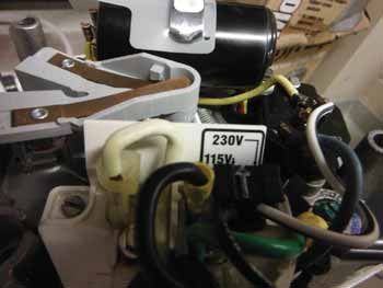
is now a part of

                                              www.lonza.com

                                      Product Stewardship

                      MAKING THE WORLD A BETTER PLACE

Lonza is committed to maintaining and improving our leadership in the stewardship of our products. One
of our initiatives is to make health, safety, and environmental protection an integral part of a product’s life
cycle – from manufacture, marketing, and distribution to use, recycling, and disposal.

Everyone involved with the product has responsibilities to address society’s interest in a healthy environment
and in products that can be used safely. We are each responsible for providing a safe workplace. All who use
and handle products must follow safe and environmentally sound practices.

For more information about the stewardship of our products, contact your Lonza Representative.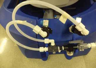
Instructions for Pulsar® Booster Pump Installation
To Simplify Installation: Please read this installation manual completely before going to the pool site.

 Tools & Equipment Needed for Install:
  Drill – Cordless Recommended                                            Tube cutters or Utility Knife

  1-3/4” hole saw and 1-1/2” NPT tap (Optional)                           RTV silicon seal

  PVC Primer/Cleaner                                                      2 Pipe Wrenches or Gas Pliers

  PVC Glue                                                                Water tight connectors for pump wiring

  Saw to cut PVC Pipe                                                     Wire for pump (14 gauge minimum required)

  Electricity for the Pulsar Control Panel and                            Pressure gauge
  Pump (115V; 15 Amp)

  PTFE (Plumbers) Tape                                                    Saddle clamps (optional)

  11/16” hole saw or paddle bit                                           1/2” NPT tap

 The Following Parts are to be Supplied by
 the Installer to Complete Installation:
  Two 1-1/2” slip x thread PVC unions for Venturi                         1-1/2” X 1/2” Schedule 80 PVC T SXF

  Two 1-1/2” threaded PVC ball valves                                     1-1/2” PVC sch 40 Pipe

  1-1/2” sch 40 PVC pipe fittings required to
  install Booster pump/Venturi loop

 rev.3 (3/12/14)    Lonza   •   1200 Lower River Road, P.O. Box 800   •   Charleston, TN 37310-0800   •   1-800-4-PULSAR   3
Instructions for Pulsar® Booster Pump Installation

              The Following Parts are Included with the Installation Kit
                Operator Manual
     Part #       Diagram #                                                  Description                              Quantity
                                                                       ®
     71811                  33                  Venturi for Pulsar Systems (1585X)                                          1
     71627                  24                  1/2” Ball Valve MF (Outlet P3)                                              2
     71588                  34                  1/2” x 1/2” Female Connector                                                1
     71626                 NS                   20ft 1/2” O.D PE Tubing                                                     1
     79214                  35                  PUL BOOSTER PUMP                                                            1
     71916                  5                   1/2” PVC Closed Nipple                                                      1
     79675                 NS                   2” Pipe end male x 1-1/2” Female Hex Bushing                                1
     79218                  6                   PUL CHECK VALVE 1/2” CEPEX USA PVC/EPDM                                     1
     79222                  7                   PUL DISCHARGE VALVE ELBOW                                                   1
     79810                  8                   PUL DISCHARGE VALVE FLOAT                                                   1
     79805                  9                   PUL DISCHARGE VALVE ARM                                                     1
     79806                  10                  PUL DISCHARGE VALVE BODY                                                    1
     71583                  11                  Discharge Valve Locknut for Feeders                                         1
     71576                  12                  1-1/2” x 3/4” x 1/8” Silicone Washer                                        1
     79811                  13                  Parker Fitting P8ME8 1/2" Nom. Male elbow                                   1
     79813                  19                  JACO White 1/2” TUBE 90 ELL                                                 3
     79664                  20                  SOLENOID DC Valve (ASCO 8212A519S0100F1)                                    2
     79812                  21                  LINE STRAINER ASSEMBLY (Small Ron-Vik)                                      1
                                                JACO White CONNECTOR 1/2” MNPT x 1/2” TUBE
     79814                  22                                                                                           3&2
                                                (Standard, Feeder ONLY)
     76255                  23                  MUN NIPPLE 1/2” PVC (1-1/2” L) NSF61 SCH                                    1
     71912                  26                  1/2” Threaded Tee                                                           1
     71617                  28                  Spray Nozzle for PS45 (1), PS140 (3)                                     1&3
     79660                  30                  AGITATION NOZZLE (1/2” SCH 40 PVC PLUG)                                     1
     79817                  31                  WASHDOWN NOZZLE (460.644) (PS45 & PS140 Only)                               1
     71888                  28                  Spray Nozzle for Spray Tree (PS 500 Only)                                   4
     71548                  25                  1-1/2” x 12” PVC Nipple #886120                                             2
     79669                 NS                   Flow Switch 24VAC/DC, SS 1/2” NPT (SC050R)                                  1
     79670                 NS                   Galvanized washer for 5/16” lag Bolt (PS 500 Only)                          4
     79671                 NS                   Zinc Alloy lag Shield 5/16” short (1-1/4”) (PS 500 Only)                    4
     79672                 NS                   Galvanized 5/16” x 2-1/2” lag bolts (PS 500 Only)                           4

                  NOTE: For Feeder only install, proceed to page 7.

 4            Lonza   •   1200 Lower River Road, P.O. Box 800   •   Charleston, TN 37310-0800   •   1-800-4-PULSAR   rev.3 (3/12/14)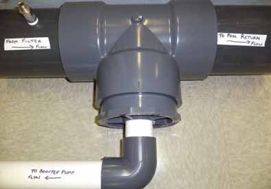
Instructions for Pulsar® Booster Pump Installation
Overview:
A 1-1/2” loop is going to be added to the main pool recirculation line. The loop will have an in-
line Pulsar ® pump to drive a venturi. The Pulsar ® inlet line will get water from the discharge of the
Pulsar ® pump. The discharge valve of the chlorinator will be hooked up to the venturi.

The Pulsar ® pump provides the correct pressure (~ 35 psi) to drive the spray and wash-down
nozzles in the Pulsar ® chlorinator. It also provides required flow through the venturi to create
vacuum to evacuate the solution from the base of the chlorinator. This installation method gives
optimal performance of the Pulsar ® chlorinator in most above and below grade installations.

The use of a pressure gauge on the discharge side of the pool pump after the filter is recommended
for correct installation of the system.

Site Assessment
Electrical:                                                               Always minimize the backpressure on the venturi.
                                                                          Avoid use of elbows after the venturi if possible.
The Pulsar ® Chlorinators require minimum                                 Never install an elbow within 3 feet of the venturi
electrical service that is outlined in the Booster                        outlet. Always use elbows on the inlet to the
pump section. The electrical service must be                              Pulsar ® pump or prior to the venturi if possible.
installed by a licensed electrician according to                          After the evacuation system has been laid out,
the local electrical code.                                                measure the height differential (in feet) between
                                                                          where the venturi will be installed and discharge
Hydraulics:                                                               valve of the Pulsar ® chlorinator. Use this height
                                                                          differential to calculate the suction lift factor in
It is critical to determine the effluent pressure
                                                                          the formula that follows. The greater the height
of the system prior to installation. This
                                                                          differential the more suction you will lose from
pressure must be measured immediately after
                                                                          the venturi. Next calculate the outlet flow using
backwashing when it will be at its highest level.
                                                                          F1 and the suction lift factor. The minimum outlet
Refer to the appropriate system diagram in the
                                                                          flow required is 2.3 gpm.
back of this manual (pages 23-25) to determine
where to measure this pressure (P1).                                      Suction lift factor          = (34 – height differential in
                                                                                                         feet) / 34
Take a pressure reading and refer to the graph
on page 13 to determine the suction capacity of                           Example: height differential is 6 feet, therefore
the system assuming that there is no suction lift                         Suction lift factor  = (34-6) / 34
correction. Record this suction capacity as F1.                                                = 28 / 34
                                                                                               = 0.82
Next, determine where the Pulsar ® pump and
venturi loop will be installed. It may be preferable                      Take the suction capacity F1 and multiply it by
to install this loop across the heater bypass                             the suction lift factor to get the actual outlet flow.
valve to use this pressure differential to enhance
system performance.                                                       The formula is:
                                                                          F1 x suction lift factor = actual outlet flow

 rev.3 (3/12/14)    Lonza   •   1200 Lower River Road, P.O. Box 800   •    Charleston, TN 37310-0800   •   1-800-4-PULSAR        5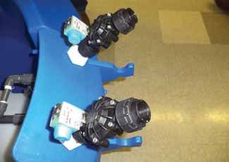
Site Assessment
Example #1: Assume that the pressure measured                            the chlorinator. Consequently, it is recommended
in the pipe is 14psi.                                                    that the inlet flow be provided from the fill water
                                                                         source if the TA of the fill water is below 100ppm.
Using the graph 1 in this manual the outlet flow
(F1) is determined to be 3.8gpm.                                         NOTE: The Fill water source method can only
                                                                         be used with the booster pump in Econo Mode
F1 x suction lift factor = actual outlet flow
                                                                         and not when the booster pump is running
3.8gpm x 0.82 = 3.1gpm = actual outlet flow
                                                                         constantly.
(This flow is acceptable) It is above 2.3gpm
                                                                         The use of fill water to the chlorinator inlet will add
which is the minimum.
                                                                         water to the pool on a daily basis in relatively small
Example # 2: Assume that the pressure measured                           amounts. A typical indoor 100,000 gallon pool
in the pipe is 25 psi. Using the graph on page 14,                       will use approximately 20 gallons of chlorinated
the outlet flow (F1) is determined to be 2.7gpm.                          solution from the Pulsar ® System per day. A
                                                                         typical outdoors 100,000-gallon pool will use
F1 x suction lift factor = actual outlet flow 2.7gpm                      approximately 60 gallons of chlorinated solution
x 0.82 = 2.2gpm = actual outlet flow                                      from the Pulsar ® System per day. The Pulsar ®
(This flow is insufficient to drain chlorinator)                          System also puts additional 200 gallons water
                                                                         a day in the pool from the washdown system
A larger pump will be required to generate                               (when in Econo Mode). If you use this installation
sufficient outlet flow. Consult with your dealer.                         method make sure that the pool has that amount
                                                                         of water being removed as to not cause the pool
Now determine where the power source will
                                                                         to overflow.
come from for the Pulsar ® Control Panel. These
considerations will help determine the length                            Fill water systems typically operate at pressures
and gauge of wire needed.                                                between 50-80 psi. This pressure is too high for
                                                                         the Pulsar ® System valves to operate properly.
The last consideration for the site assessment
                                                                         It is therefore necessary to install a pressure
is the fill/tap water source and the type of pH
                                                                         regulator on the inlet flow to the Pulsar ® System.
control system to be used. If Carbon Dioxide will
                                                                         This regulator must be installed directly at the fill
be used for pH control, it may be preferable to
                                                                         water source. This will insure a reduced pressure
provide the inlet flow to the chlorinator from the
                                                                         in the flexible polyethylene tubing and solenoid
fill water source. Typically, Carbon Dioxide pH
                                                                         valve on the inlet side of the chlorinator. Adjust
control systems will raise the Total Alkalinity of
                                                                         the pressure regulator to provide between 30-35
the pool water to well over 100ppm. This TA level
                                                                         psi inlet water pressure. See diagram below for
will increase the tendency for scale formation in
                                                                         proper fill water plumbing hook-up.

                                                         Direction of Flow

                 Fill                       Inlet                    Pressure
                                                                                                Pulsar ®
               Water                      Shut-Off                   Regulator
                                                                                                 Inlet
               Source                      Valve                     0-60 psi

  6           Lonza   •   1200 Lower River Road, P.O. Box 800   •   Charleston, TN 37310-0800   •   1-800-4-PULSAR   rev.3 (3/12/14)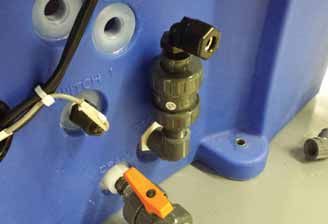
Installation of the Pulsar® Control Panel
General Description:                                                     Note: The Pulsar ® Control Panel must
                                                                         not be located in direct sunlight or where
The Pulsar ® Control Panel must be plugged                               temperature will exceed 115°F.
into a 115V/15A(minimum) dedicated outlet.
                                                                         Danger: Leave the Pulsar ® Control Panel
The 115V powers the controller as well as the
                                                                         unplugged until all connections are made
booster pump to optimize energy usage. A
                                                                         and the front panel of the Control Panel is
step down transformer converts the voltage to
                                                                         closed. Maintain control of the plug at all
24VDC for powering the low voltage solenoids.
                                                                         times during the wiring of high voltage.
There are two input signals to the Pulsar ®
                                                                         1. Mount the Pulsar ® Control Panel on a wall
Control Panel. They are:
                                                                            (within 8 feet of dedicated outlet) that will
A. REQUIRED - Flow (existence of flow in the                                allow for installation of the flow switch and
   pool return line). See figure A & B, page 8.                             chlorinator in the desired locations.
B. OPTIONAL - Chlorine Demand. The chlorine                              2. The flow switch must be installed in the pool
   demand signal is generated by an ORP                                     return line near the inlet to the booster pump
   controller. If an ORP controller is not used,                            loop.
   the Control Panel uses an integrated timer for
                                                                         3. The feeder should be located in an area with
   chlorine output control.
                                                                            ample room for filling with chemical and
There is a specialized cable that connects the                              access for maintenance.
Pulsar ® Control Panel to the feeder junction
                                                                         4. The cables should be routed to stay out of
box (J-Box). This cable carries the signals to
                                                                            contact with water and not create any trip
the Control Panel from the lid and level switches
                                                                            hazards.
and from the Control Panel to the solenoids.
                                                                         5. If an ORP controller output (115V, NEMA
Important: The power and signal cables
                                                                            5-15R) is used with the Pulsar® Feeder the
(Figure C, page 8) must be considered when
                                                                            connection of the ORP controller to the Pulsar®
laying out the equipment installation. The
                                                                            Control Panel is made with an extension cable
length of wire for:
                                                                            of the proper length. See figure F, page 8.
A. Power cable – 8 feet (2.44m)
                                                                         6. The appropriate gauge wire should be used
B. Flow switch cable – 32 feet (10m)                                        to connect the Booster pump to the Pulsar ®
C. Control Panel to Feeder cable – 16 feet (4.9m)                           Control Panel.
D. Power from Control Panel to Booster Pump –                            7. Connect the cable from the J-Box (on the
   TBD (wire provided by Installer)                                         back of the feeder) to the Pulsar ® Control
E. ORP Controller to Control Panel – 2 feet (0.6m)                          Panel. See figures D & E, page 8.
   (extension cable supplied by Installer)                               8. Connect the flow switch cable from the
For longer Flow Switch (IFM) and Control                                    Pulsar ® Control Panel to the installed flow
Panel/Feeder (TURCK) cables call                                            switch. See figure C, page 8.
IFM: (800) 441-8246 or www.ifm.com                                       9. Make sure the front panel is closed securely
     Patch Cables: 10m-EVT045, 5m-EVT044                                    and plug in the power cable for the Pulsar ®
TURCK: (800) 441-8246 for local distributor                                 Control Panel to a dedicated 115V outlet.
       or www.turck-usa.com                                                 See figure G, page 8.

 rev.3 (3/12/14)   Lonza   •   1200 Lower River Road, P.O. Box 800   •    Charleston, TN 37310-0800   •   1-800-4-PULSAR   7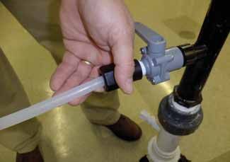
Installation of the Pulsar® Control Panel

Figure A                                                                              Figure D

                                                                                      Figure E

Figure B

                                                                                      Figure F

Figure C

                                                                                      Figure G

 Power Cable to               Flow Switch            115V power out
 115V Outlet                  Cable                  to Booster Pump

                     Feeder Cable              Chlorine Demand
                     to J-Box                  from ORP

  8          Lonza    •   1200 Lower River Road, P.O. Box 800   •   Charleston, TN 37310-0800   •   1-800-4-PULSAR   rev.3 (3/12/14)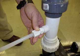
Pulsar® Footprint - Model P45

 rev.3 (3/12/14)   Lonza   •   1200 Lower River Road, P.O. Box 800   •   Charleston, TN 37310-0800   •   1-800-4-PULSAR   9
Pulsar® Footprint - Model P140

10      Lonza   •   1200 Lower River Road, P.O. Box 800   •   Charleston, TN 37310-0800   •   1-800-4-PULSAR   rev.3 (3/12/14)
Pulsar® Footprint - Model P500

 rev.3 (3/12/14)   Lonza   •   1200 Lower River Road, P.O. Box 800   •   Charleston, TN 37310-0800   •   1-800-4-PULSAR   11
Booster Pump
The 1 H.P. pump is to be wired for 115V single-                         NOTE: It is critical to always have water flow
phase service only. The pump is shipped for 230V                        to the booster pump before starting up with
single-phase installation. Move the jumper to                           a new or existing installation. Failure to have
configure pump for 115V operation. 208V service                         water in the booster pump during start-up can
is not adequate and will harm the pump. Use                             result in seal failure. To prevent seal failure
115V service with a minimum 15 amp breaker.                             on start-up, crack open the union fitting on
Important: The booster pump electric service                            the booster pump discharge until water runs
must be installed by a licensed electrician                             out freely. This will indicate that the booster
according to the local electrical code.                                 pump has water in the volute and it is safe to
                                                                        start the pump.

It is recommended to have the power supply                                                                  Tighten union after pump
to the Pulsar ® pump interlocked to the pool                                                                is primed with water.
recirculation pump through an external relay
shut-down. The Pulsar ® Control Panel receives                          Installation of equipment
a signal from the flow switch mounted in the Pool
                                                                        Place the equipment, pump and chlorinator, in
return Line (near the inlet to the Booster pump).
                                                                        the poolroom in a convenient location.
If no flow is detected, the controller will not
energize the Booster pump. This is to prevent                           Shut off the pool recirculation equipment before
the Booster pump from running dry when the                              proceeding with the installation. Review the
filter is being backwashed or the pool pump is                          installation diagram prior to installation.
shut down.
                                                                        Refer to “Footprint” dimensions on pages 9-11
                                                                        to determine placement in pump room.

                                                                        PS500 ONLY: The feeder must be bolted to the
                                                                        floor using provided lag bolts, washers and
                                                                        shields.

 12          Lonza   •   1200 Lower River Road, P.O. Box 800   •   Charleston, TN 37310-0800   •   1-800-4-PULSAR       rev.3 (3/12/14)
Pulsar® Installation 1 HP Booster Pump and 1585X Venturi rev.3 (3/12/14) Lonza • 1200 Lower River Road, P.O. Box 800 • Charleston, TN 37310-0800 • 1-800-4-PULSAR 13
Installation
1. Based on your site assessment, drill and tap                          3. Thread the nipple into the 1-1/2” tapped hole
   a 1-1/2” NPT hole down stream of the pool                                or saddle clamp.
   filter. NOTE: Saddle clamps or tee’s can be
   used as an alternative. This is one of two
   holes that will be needed in the installation.
   The hole should be drilled on the side or
   bottom of the pipe, if the pipe is horizontal.
   NOT ALL PIPES RUN FULL.

                                                                         4. Glue the 2” x 1-1/2” reducer bushing (#79675)
                                                                            into the inlet of the Pulsar ® pump.

2. Cut both of the 12” x 1-1/2” PVC nipples
   (#71548) in half. (4 pieces). Take one of the
   pieces and apply PTFE (plumbers) tape to the
   threads. On top of the PTFE tape add a silicon
   seal bead around the threads. The silicon seal
                                                                         5. PTFE tape the threaded end of one of the
   helps to make a good seal. Wipe off any excess.
                                                                            nipples that was cut in half. Place a bead of
                                                                            silicon seal around the taped threaded ends.

                                                                         6. Screw and tighten the two pieces into the
                                                                            inlet and outlet of the Pulsar ® pump.

 14           Lonza   •   1200 Lower River Road, P.O. Box 800   •   Charleston, TN 37310-0800   •   1-800-4-PULSAR   rev.3 (3/12/14)
Installation
7. Take the 1-1/2” ball valve and glue it onto 11. Using 1-1/2” PVC pipe, connect the inlet side
the nipple that has been screwed into the of the Pulsar ® pump to the 1-1/2” ball valve
pool piping in step #3. This is what makes installed in step #7.
the connection
12. Piping the discharge side of the Pulsar ® pump
from the pool
will involve installing a venturi and reducing
recirculation
tee. See Pulsar ® diagram on Page 22 for
system to the
reference. Place and glue the 1-1/2” x 1/2”
Pulsar ® pump
reducing tee on the 1-1/2” cut nipple on the
inlet using 1-1/2”
discharge side of the pump. This reducing tee
PVC piping.
will have a 1/2” male tubing fitting screwed
8. Drill and tap another 1-1/2” NPT hole into it that will provide the inlet water to the
downstream of the first hole that was drilled chlorinator.
and tapped. This hole accommodates the
discharge side of the Pulsar ® pump. NOTE:
If automated controllers are used in the
system, the drilled and tapped hole must
be placed downstream of the ORP and pH
probes location. This is to avoid problems
that may occur with the controller
operation. See installation diagram. Thread
one of the cut 1-1/2” nipples into the 1-1/2”
tapped hole or saddle clamp.
9. Take a 1-1/2” ball valve and glue it onto the
nipple installed
in Step 8. Please
make sure that
there is a straight
connection back
into the pipe, no
elbows. This is
to connect the
pool recirculation
system to the
discharge side
of the Pulsar®
venturi.
10. Tie in the electrical to the Pulsar ® pump
making sure you have the pump configured
for the correct voltage.
rev.3 (3/12/14) Lonza • 1200 Lower River Road, P.O. Box 800 • Charleston, TN 37310-0800 • 1-800-4-PULSAR 15Installation
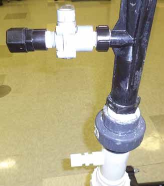
13. Take the black venturi and PTFE (plumbers) NOTE: Make sure
tape all the threaded ends. Take the two the flow through
unions (makes for easy removal of venturi, the venturi is in the
for cleaning, after installation) and screw one proper direction.
on each end and tighten. Take and thread the Connect the other
3/4” x 1/2” reducing coupling onto the venturi. end of the venturi
to the discharge
side of the Pulsar®
pump using 1-1/2”
PVC pipe.
15. The recirculation loop is now complete.
Feeder Assembly
Note: Some components may come pre-
assembled.
A. Remove the Hopper, Lid, Valve Plate with
Manifold and Spray Shield and place on a
clean dry surface.
B. Wrap the Discharge Valve Body (#79806)
threads with at least 5 wraps of PTFE
(plumbers) tape before installation in the
feeder base.
C. Put together the Discharge Valve Assembly:
First, install the Discharge Valve Arm (#79805)
on the Body (#79806). Place the Discharge
Valve Gasket (#71579) over the taped threads
and install the DV Float (#79810).
NOTE: Do not install the DV Float before
installing DV Arm on Body as this will place
14. Connect the venturi as close as possible to
excess stress on the Arm.
the ball valve installed in step 8 using a short
section of 1-1/2” PVC pipe.
16 Lonza • 1200 Lower River Road, P.O. Box 800 • Charleston, TN 37310-0800 • 1-800-4-PULSAR rev.3 (3/12/14)Installation
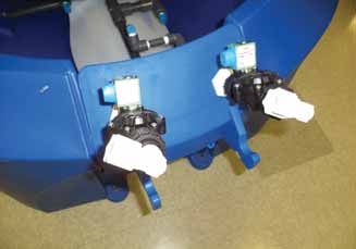
Feeder Assembly (cont’d)
D. Install the Discharge Valve Assembly in the H. Install the Wash-down and Well Agitator
Base of the Feeder and use the DV Nut to Nozzles in the Wash-down Manifold.
secure the DV in place making sure it is NOTE: Do not use PTFE tape on the Valve
upright as indicated by the marks on the Body Union. There is an o-ring that forms the
Feeder Base. water tight seal.
I. Replace the Valve Plate with Manifolds on the
Feeder Base.
J. Orientate so that the Wash-down Nozzles
point towards the center of the Spray Shield.
K. Replace the Hopper and Lid on the Feeder
Base.
PS500 ONLY: Push Hopper back to provide
room for installing solenoids.
L. Wrap the threads on the valves mounts with
at least 5 wraps of PTFE (plumbers) tape.
Note position of Gasket inside Feeder Base
E. Replace the Spray Shield.
F. Install the Spray Nozzle(s) in the Spray
Manifold and orientate facing straight up.
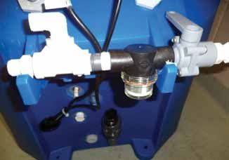
M. Reference the instructions in Solenoid box
for Solenoid Installation (figures 1 - 3).
G. Wrap both the Wash-down and Well Agitator N. Locate the flow arrow (figure 1, page 18) on
Nozzles with PTFE (plumbers) tape. the Solenoids (#79664) and make sure the
outlet port of each Solenoid is mounted on
the valve mount. Orientate the valve so the
coil is on top of the valve and closest to the
feeder (figure 1a, page 18).
rev.3 (3/12/14) Lonza • 1200 Lower River Road, P.O. Box 800 • Charleston, TN 37310-0800 • 1-800-4-PULSAR 17Installation
Feeder Assembly (cont’d)
O. Note the label on the DIN connector and
connect the DIN connector to the appropriate
Solenoid with the Feed Solenoid on the left
and the Wash-down solenoid on the right
when facing the feeder.
figure 1
P. Wrap all the male ends of the ball valves,
nipples and tube fittings received with the kit
with PTFE tape.
Q. Assemble the Inlet Manifold as shown (figures
1b - 1c). Install the elbow tube fittings in the
Solenoid and orientate as shown (figure 2, figure 1a
page 19).
NOTE: Do not overtighten Line Strainer. Use
the longer piece of tubing (24”) to connect
the top inlet fitting to the Wash Solenoid
(right). Use the shorter piece of tubing (18”)
to connect the bottom inlet fitting to the Feed
Solenoid (left) (figure 3, page 19).
R. Install the Check Valve Assembly on the DV as
shown (figures 4 - 4a, page 19). Make sure Check
Valve flow arrow points away from feeder.
figure 1b
NOTE: See arrow on Check valve (figure 5a)
and install threaded connectors (figure 5b).
NOTE: Refer to diagram of DV Assembly
on page 21 of Operator’s Manual.
NOTE: PVC elbow can be 45º or 90º. There
is an extra closed nipple (#71916) with
Feeder Only Installation Kit. figure 1c
18 Lonza • 1200 Lower River Road, P.O. Box 800 • Charleston, TN 37310-0800 • 1-800-4-PULSAR rev.3 (3/12/14)Installation
figure 5a
figure 2
figure 5b
figure 3
figure 6
figure 4
figure 4a figure 7
rev.3 (3/12/14) Lonza • 1200 Lower River Road, P.O. Box 800 • Charleston, TN 37310-0800 • 1-800-4-PULSAR 19Installation Connect Feeder to Booster Pump/ Venturi Loop A. NOTE: Locate the feeder so that the outlet tubing length is as short as possible. B. Connect the inlet manifold to the Tubing connector on the Tee above the booster pump using the 1/2” tubing provided with the feeder (figure 6, page 19). C. Install female Parker fitting on ball valve as shown below. Connect the 1/2” tubing from the venturi to the discharge valve of the feeder (figure 7, page 19). D. Open the 1-1/2” ball valves and prime the Pulsar ® pump. WARNING: Never start booster pump without priming the pump. Start and run the Pulsar ® pump for 3-4 minutes. Open the 1/2” gray valves and allow water to flow into the chlorinator, checking for leaks. E. Refer to the Operators Manual for Pulsar ® chlorinator operation. 20 Lonza • 1200 Lower River Road, P.O. Box 800 • Charleston, TN 37310-0800 • 1-800-4-PULSAR rev.3 (3/12/14)
Installation of the Pulsar® Control Panel
Power Up:
1. Once powered up, set the Wash timer to 5
   minutes by going to the Wash Timer Screen,
   and pressing the UP arrow until 5 is shown on
   the screen. See figures H & I.
2. Then go back to main Menu and press the Set Up                             Figure H

   button. On the setup screen, set to ORP control
   YES or NO. Setting YES will select the ORP plug to
   control feed, Setting NO will select the Feed Timer
   to select feed rate. See figure J.
3. Press the Right Arrow to select the next screen
   which will show your selection for Feeder Model
                                                                              Figure I
   Size and Booster Pump Mode. See figure K.
4. You will have to Log in as “Tech” to select the
   Feeder Model Size. Press the LOG IN button and
   select TECH from the User Name dropdown, then
   enter code 785727 by highlighting the numbers by
   using the arrows and ENT button. Then, highlight
   OK at the bottom and press ENT.
                                                                              Figure J
5. Select Feeder Size, and Booster Pump Mode. If
   this is the first power on for the panel, you must
   toggle this switch to activate.
6. Once selected, press the Left arrow to go back to
   the ORP/Feed Rate screen, the display in the top
   middle will read the Feeder Model Size Selected.
   The Feed Rate button is deactivated when ORP                               Figure K
   is set to YES. When ORP is set to NO, then you
   can set up the Feed Rate timer. See figure L.
7. On the Feed Rate Screen press the “Eject” arrow
   to get back to the Main screen. Here you can now
   press the FEED START button to start feeding the
   water as required by the controller.
8. The Chem Balance button is for the End User                                Figure L

   to check their chemical balance. It provides for
   the Saturation Index calculations for the pool
   chemistry. See figure M. Press the X box to close
   the screen.
9. The E-STOP button will shut off all OUTPUTS
   until it is pressed again.
                                                                              Figure M

 rev.3 (3/12/14)   Lonza   •   1200 Lower River Road, P.O. Box 800   •   Charleston, TN 37310-0800   •   1-800-4-PULSAR   21
Pulsar® Installation Kit
flow to
pool
NOTE: All parts with numbers 25
are included in Pulsar ®
Installation Kit. 1-1/2” Slip
PVC Ball Valve
(installer provides)
cut 1-1/2”
PVC pipe
(installer provides)
24
34
33 1-1/2” thread x slip
PVC union
(installer provides)
flow from
feeder
1-1/2” slip x 1/2” FNPT TEE
(installer provides)
22 cut 1-1/2”
PVC pipe
(installer provides)
flow to
feeder
25
35
flow
from
pool
25
1-1/2” Slip PVC Ball Valve
(installer provides)
22 Lonza • 1200 Lower River Road, P.O. Box 800 • Charleston, TN 37310-0800 • 1-800-4-PULSAR rev.3 (3/12/14)rev.3 (3/12/14) Lonza • 1200 Lower River Road, P.O. Box 800 • Charleston, TN 37310-0800 • 1-800-4-PULSAR 23
24 Lonza • 1200 Lower River Road, P.O. Box 800 • Charleston, TN 37310-0800 • 1-800-4-PULSAR rev.3 (3/12/14)
rev.3 (3/12/14) Lonza • 1200 Lower River Road, P.O. Box 800 • Charleston, TN 37310-0800 • 1-800-4-PULSAR 25
Lonza Emergency Action Network (LEAN)
           The Lonza Emergency Action Network (“LEAN”) is Lonza’s emergency action system. Call the
           LEAN system at 1-800-654-6911) in North America, and at (Country Code for the United States)
           423-780-2970 elsewhere in the world. The LEAN system is available 24 hours a day, 7 days a week
           for assistance with spills, injuries and emergencies of any kind. It uses computers and other systems
           to make Lonza’s environmental, technical transportation, toxicological and other expertise about its
           products readily available to anyone needing assistance. The LEAN system also includes emergency
           response teams capable of providing on-site support throughout North America.

                                                              (800) 654-6911
                    (From outside North America, call after the country code for the US, 423-780-2970)

           Additionally, in the event of an emergency, CHEMTREC (Chemical Transportation Emergency Center)
           should be contacted. CHEMTREC is a national center established by the Chemical Manufacturers
           Association (CMA) in Washington, DC, to relay pertinent emergency information concerning specific
           chemicals on request.

           CHEMTREC has a 24-hour toll-free telephone number (800) 424-9300, intended primarily for use
           by those who respond to chemical transportation emergencies. CHEMTREC may also be accessed
           through the CMA website at www.cmahq.com.

           Material Safety Data Sheets (MSDS) can be obtained by contacting (800)-511-MSDS.

Pulsar ® is a registered trademark of Arch Chemicals, Inc. which is now part of Lonza. The configuration of the briquette-shaped chemical tablet is a registered
                                                           trademark of Arch Chemicals, Inc. 3/14
You can also read