Ultrasonic Multi-Skip Inspection at Clamped Saddle Supports
←
→
Page content transcription
If your browser does not render page correctly, please read the page content below
18th World Conference on Nondestructive Testing, 16-20 April 2012, Durban, South Africa

          Ultrasonic Multi-Skip Inspection at Clamped Saddle Supports
                           Maarten LORENZ 1, Stefan LEWANDOWSKI 2
                   1
                     Shell Global Solutions International B.V.; Amsterdam, The Netherlands;
                 Phone: +31 6520 96234, Fax: +31 +31 2063 02989; maarten.lorenz@shell.com
                  2
                    Shell UK Ltd.; Aberdeen, United Kingdom; stefan.lewandowski@shell.com

Abstract
The ultrasonic Multi-Skip inspection technique has made a modest entry in the world of advanced ultrasonic
inspection methods. As an intermediate-range inspection technique, it has proven particularly useful for the
inspection of pipes at clamped saddle support locations. In order to shed some light on its capabilities and
limitations, this paper is presenting some results of Multi-Skip inspections done on 36” and 48” diameter pipe of
34 mm as well as 9.5 mm wall thickness. The sensitivity and the accuracy of the technique are demonstrated
using field measurement results and the feasible application range is discussed. With its high sensitivity to local
wall loss, the Multi-Skip inspection technique appears to be a welcome addition to the currently available
Guided-Wave and CHIME inspection methods for inaccessible locations.

Keywords: Multi-Skip, ultrasonic inspection, pipe support, inaccessible location

1. Introduction
Pipe supports may have different forms and dimensions. In all cases, however, at least the 6
o‟clock pipe position is resting on the support and is as such inaccessible for conventional
(wall thickness) inspection techniques. The most common type of support is the simple
sleeper support: the pipe is resting on a steel bar or an H-profile, and only a small part of the
pipe is touching the support, at the 6 o‟clock position (Figure 1a). Of the more complex
support structures, the clamped saddle support (Figure 1b) is particularly challenging for
inspection, because of the large area covered by the saddle.
For inspection of the simple sleeper support locations, where the top half of the pipe is usually
accessible, the semi-quantitative Pipe Support Tool was developed by Shell in the late 1990‟s.
It makes use of ultrasonic shear waves travelling around the pipe in the circumferential
direction, where probes are set up in pitch catch position. The interaction of the ultrasonic
waves with possible wall loss at the 6 o‟clock position leads to changes in the received signal
amplitude. The Pipe Support Tool is a fast & simple screening tool capable of distinguishing
between no or light (50%) local wall loss. It can be
applied on pipe diameters ranging from 3” to 18”, and of various thicknesses.

   (a)                                                          (b)

             Figure 1. Simple sleeper support (a) and a typical clamped saddle support location (b).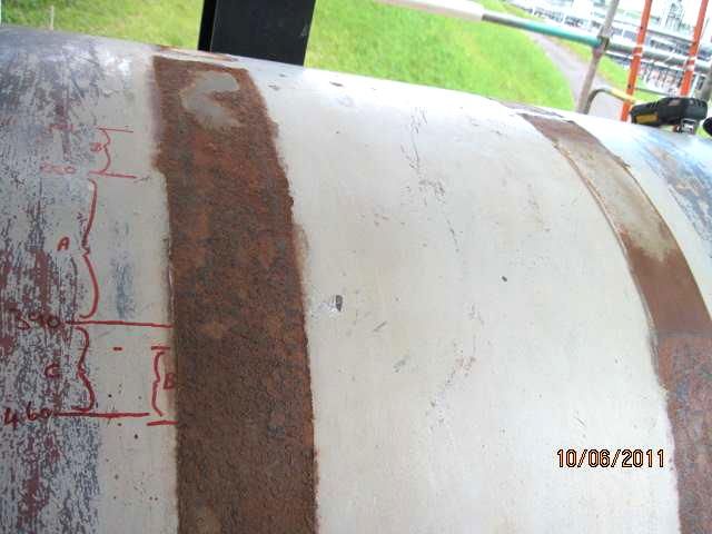
On pipes with clamps at support locations, the Pipe Support Tool is not applicable anymore
because of top access restrictions. Removing the clamps would be required, which may be
possible in some cases. However, if the pipe (also) rests on a saddle, then the Pipe Support
Tool methodology will still detect wall loss, but won‟t be able to give any size indication of
the wall loss anymore, because of the possible extended affected areas under the saddle (not
only local at the 6 o‟clock position). If on top of that the pipe size increases well above 18”,
another intermediate range ultrasonic approach is needed to inspect pipes at clamped saddle
support locations non-intrusively. This paper will describe the application of the ultrasonic
Multi-Skip inspection technique for this purpose.

                Tx                                 support                                       Rx

                            Figure 2. Basic ultrasonic Multi-Skip transmission set-up;
                     the 1-skip (blue), 2-skips (green) and 3-skips (red) ray paths are shown.

2. The Multi-Skip Inspection Method
2.1 Basic Principles

The principles behind Multi-Skip (or M-Skip®) have been very well described [1]. Here a
short explanation will be given in order to show the complexity of a basically simple
approach. The ultrasonic Multi-Skip method is based on the use of shear waves in a
transmission set-up, where the source probe is located on one side of the support and the
receiver probe on the other side, aligned in the axial direction of the pipe (figure 2). Many ray
paths exist, which correspond to different skips signals. One skip is defined as a wave coming
from the top surface, reflecting from the back and arriving at the top again.
The presentation in the form of rays (figure 2), may lead to confusion. The rays suggest
merely discrete (local) interaction with the surfaces, while in reality a wrapped ultrasonic
wave front is propagating through the material, interacting multiple times with all points on
both surfaces. This is illustrated by the computational finite-difference modelling snapshot
shown in figure 3. The amplitudes of the skip responses depend on the intensity of the wave
field, which is determined by the beam spread (bundle characteristics) of the transducers.

 Figure 3. A snap shot of an ultrasonic wave field propagating through a plate, with the source at the left hand
                 side; the receiver on the right hand side will record a series of (skip) signals.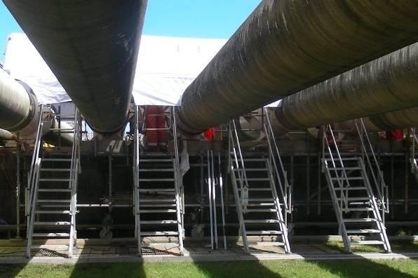
Figure 4. Coverage of Multi-Skip – any wall loss will act as a secondary source.

2.2 Multi-Skip Wave Propagation and Responses

Not all parts of the wave front that interacted with a particular point at the surface will reach
the receiver location. At the receiver location, only (discrete) parts of the wave front will be
recorded, while other parts are missing the receiver crystal in the defect-free situation. This
can be seen in figure 3 (parts of the wave front indicated by the small circles). One might
think that this could potentially lead to missing defect responses when the wave front interacts
with local wall loss somewhere on its way between the probes. This, however, is not the case,
because at the location of the wall loss diffraction/refraction will take place. In other words,
the local wall loss area will act as a secondary source, sending waves into a range of
directions. The diffracted/refracted wave front will in fact travel along alternative paths, as is
shown in Figure 4. Hence, in practice, any localised area of wall loss will generate a response
which will be recorded by the receiver, independent of the location of the wall loss with
respect to the receiver.
It is worth mentioning that the Multi-Skip method is very sensitive to the presence of any wall
loss. This is shown in the elastic modeling examples of figure 5. This means that it generally
won‟t be difficult to prove from the Multi-Skip response signals that no wall loss is present.

     Figure 5. Snap shots comparing the wave field interaction with wall loss to the defect-free situation;
                             notice the significant change in recorded response.

2.3 Calculating Wall Loss

In practice, Multi-Skip measurements are made with scanning ultrasonic Time of Flight
Diffraction (ToFD) equipment, providing grey-level plots showing amplitude as function of
scan position (x-axis) and time (y-axis), as shown in figure 6.
The general (average) wall thickness can be calculated from the arrival times of a series of
skip signals using a least-squares fit algorithm. A local wall loss response will show up as an
arc-type signal somewhere between two skip signals (see right picture in figure 6). Although
there is a non-linear relation between the travel time of a skip signal and that of a local wall
loss response, it is not difficult to calculate the local wall loss based on the difference between
the skip and the wall loss signal arrival times. For the slug catcher configuration, the relation
between wall loss and travel time difference (with respect to a skip signal) is almost linear.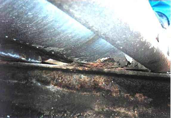
Figure 6. A ToFD representation of Multi-Skip measurements; interaction with local wall loss results in the
                                     earlier arrival of the defect signal.

           (a)                          (b)                          (c)                          (d)

Figure 7. Schematic representation of four different characteristic Multi-Skip wall loss responses resulting from
               four different wall loss areas (time axis vertical and scan direction horizontal).

Generally, four different wall loss profiles can occur, which have distinctly different Multi-
Skip responses as shown in figure 7:

    1.   Short in the axial as well as in the circumferential direction (figure 7a);
    2.   Short in the axial and long in the circumferential direction (figure 7b);
    3.   Long in the axial and short in the circumferential direction (figure 7c);
    4.   Long in the axial as well as in the circumferential direction (figure 7d).

From the Multi-Skip responses shown in figure 7 it is clear that if a wall loss defect is longer
in the axial direction (along the line between the probes) than one skip distance, the skip
signal is interrupted. This is an important indication, because the Multi-Skip method only
provides arrival time difference and does not discriminate between an area of wall loss being
hit once or more times by a particular skip signal. Hence, the wall loss values calculated from
the Multi-Skip wall loss response arrival times are worst-case values. So, for example, if a
skip signal interacts 3 times with an area of 2 mm wall loss, the corresponding Multi-Skip
response will indicate a total of 6 mm (accumulative) wall loss.
Typical Multi-Skip responses as shown in figure 7 have been observed on test samples and in
practice. Continued recording of the defect-free skip signal is a reliable indication of having a
truly local defect of which the wall loss, as calculated from the arrival time differences
between skip and defect signals, is accurate (and not an overestimation).

3. Multi-Skip Support Inspection Applications
3.1 Slug Catcher at Shell UK’s St Fergus Gas Plant

3.1.1 Description of the structure
In 2010, the condition of the slug catcher of St Fergus Gas Plant (commissioned in 1982) had
to be established in order to prove that it is still fit for service. The slug catcher is a huge steel
structure, consisting of 13 parallel 275 m long pipes of 36” diameter and ~34 mm wall
thickness, made of fine grain carbon manganese steel in accordance with API-5XL60 and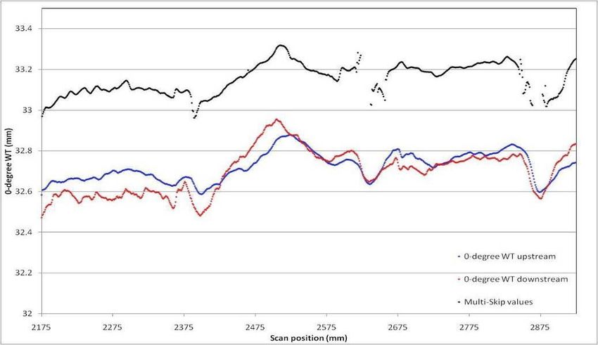
operating at ambient temperature. Most parts of the slug catcher are accessible for
conventional inspection techniques and both internal as well as external degradation can be
readily detected. Assessing the integrity of the slug catcher pipes at the clamped saddle
support locations (as shown in figure 1b), however, has proven to be difficult. Since water
ingress may have occurred in any space between the saddle and the pipe, external wall loss
corrosion may have taken place over the years. Due to the construction of the clamped saddle
support, identifying wall loss using conventional non-destructive testing methods is not
possible. There were 143 clamped saddle support locations which had to be inspected. At the
support location, the pipes were once painted with a primer and covered with a bitumen wrap.

3.1.2 Minimum detectable wall loss
Based on corrosion and fitness-for-service calculations, it was required to demonstrate that no
wall loss defects deeper than 4 mm were present. This set the wall loss detection threshold for
the inspection technique. However, the sensitivity of the inspection technique is also
depending on the aspect ratio of the wall loss area (diameter/depth). From the expected
corrosion morphology it was concluded that the inspection system for the slug catcher
clamped saddle support locations should be sensitive enough to detect a (semi-spherically
shaped) corrosion area with an aspect ratio (diameter over depth) as low as 10. With a
minimum detectable wall loss of 4 mm, this translates into a wall loss area diameter of 40
mm. Hence, the inspection technique should be sensitive enough to detect defects of 4 mm
deep (or deeper) with a diameter of 42 mm (or larger). In this case, with 36” diameter and an
approximate 34 mm wall thickness, such an area of wall loss is much smaller than the
detection limit (~9% cross-sectional wall loss) of the Guided-Wave technique.

3.1.3 Multi-Skip sensitivity requirements
In the case of the St Fergus clamped saddle support, 1.6 m had to be covered: 1.4 m support
width + friction clamps and probes located 100 mm from the start/end of the support in order
to be able to detect wall loss under the friction clamps and at the edges of the support. The
range limitation of the Multi-Skip technique will mainly depend on the roughness of both
inner and outer surface (scattering the signal), the presence and type of paint layer
(absorbing/disturbing the signal) and the quality of the probes/equipment (signal quality).
The minimum detectable wall loss in case of the St Fergus slug catcher at the clamped saddle
supports was set to 4 mm, with a diameter of 40 mm. An ultrasonic response from such a
relatively small wall loss defect will be of considerably lower amplitude than that of a regular
skip signal response. The sensitivity of the system is therefore determined by its dynamic
range, i.e. by the achievable signal-to-noise ratio (SNR).
A 60 degree probe angle was found to be most suitable for Multi-Skip inspections in this case.
A theoretical Multi-skip calculation model has been used with this angle to determine the
amplitude difference between the strongest skip signal and the response from a spherical wall
loss defect for a range of diameters. Obviously, the smaller diameter of the defect, the lower
the noise level has to be in order to see the defect response in a Multi-Skip measurement.
According to the calculations, in case a 40 mm diameter defect has to be detected, the
minimum required SNR level has to be 12 dB. The depth of the defect is assumed not to have
an influence on the local wall loss response or skip signal amplitude (for wall loss
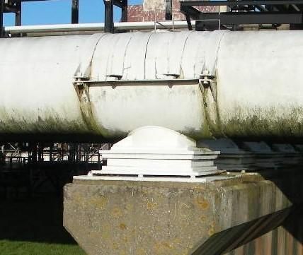
Figure 8. Multi-Skip scanner and probe assembly as developed & constructed by Sonomatic Ltd.

distance which the ultrasonic signal has travelled and that is not only a function of wall
thickness, but also of probe distance. In order to be able to attribute a change in arrival time of
a Multi-Skip response to a change in the wall thickness, the probe centre separation (PCS)
should be kept constant. In order to keep the PCS constant it is not sufficient to make sure that
the scanner rings are fitted at exactly the same distance for all positions around the pipe. It is
also required that the probes shall remain in-line (facing each other) to within 2 degrees. This
was achieved with probes travelling along a fixed track and scan motors which are
electronically (master-slave) coupled (see left picture in figure 8).

3.1.5 Probe selection
Broadband frequency probes were selected, with a crystal size of 12 mm, a centre frequency
of 2 MHz and an angle of 60° to meet the SNR (12 dB) requirement. Higher centre
frequencies (like 5 MHz) may generate a shorter wavelet, but because of the long travel path
and many surface interactions, most higher frequencies will be strongly attenuated above 2
MHz. With respect to the main angle of incidence, a 60° angle has found to be optimum in
this configuration, since the time separation between skip signals is larger than with 70
degrees, while the signal is interacting fewer times with the surface (less signal loss) than 45
degrees. As can be seen from the right picture in figure 8, probes were equipped with Multi-
Skip and 0-degree transducers in order to be able to simultaneously measure both signals. The
0-degree signals allow for the determination of the pipe wall thickness at both sides of the
support, so possible general internal wall loss can be taken into account.

  Figure 9. Example of a (field data) sensitivity graph in terms of minimum detectable wall loss area diameter
     instead of SNR, using a conversion from SNR to defect diameter as calculated by a theoretical model.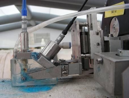
3.1.6 An alternative way to track sensitivity
In practice, it is fairly difficult to meet >12 dB SNR along the full scan, because of the
amplitude reduction due to local surface roughness, the presence of coating layers and probe
alignment variations. In order not to miss a 40 mm diameter wall loss defect, the sensitivity
level shall not drop below 12 dB for over 40 mm scan length. However, if this requirement is
locally not met during an inspection, this would mean that the entire inspection would fail. In
order to avoid such problems in practice, it is suggested to look at sensitivity in a more
dynamic way. Instead of tracking the SNR as sensitivity level, the diameter values of the
corresponding wall loss defects are used as sensitivity level. For instance, instead of
discarding the whole scan because of a local drop below the 12 dB threshold, a local
sensitivity to 50 mm diameter defects could be regarded tolerable if no wall loss is detected
anywhere in the vicinity of that location. A sensitivity graph of a Multi-Skip scan could
therefore look like the one shown in figure 9.

  Figure 10. Smart access options: movable scaffolding on rails (after removal of stairs) and inflatable weather
                                                  protection.

3.1.7 Multi-Skip inspection results from the St Fergus slug catcher
After successful testing of the scanner and probe set-up on a real-size mock-up with artificial
wall loss defects, the complete inspection of 143 supports was performed by Sonomatic Ltd in
40 days. Contributing to this achievement were the deployment of smart access solutions, in
the form of movable scaffolding (on rails) and inflatable weather protection (see figure 10).
All recorded data sets met the required data quality (sensitivity and accuracy) requirements to
an acceptable level and no significant wall loss was observed. Minute variations in the general
wall thickness (0.1-0.4mm) were detected. Such local variations in wall thickness in the
circumferential direction seem to be constant in the axial direction and could be regarded as
very shallow “grooves” resulting from the manufacturing process. The corresponding Multi-
Skip responses of figure 11 show good agreement with the local zero-degree wall thickness
variations as measured at the probe locations on either side of the support.
It has been found that the average wall thickness values calculated from Multi-Skip responses
are generally a little higher (0.5 - 0.8 mm) than the 0-degree values (see figure 11). The exact
reason for this discrepancy has not been determined yet, but is believed to be caused by a
combination of possible phenomena: wave velocity variations, anisotropy of steel and/or
coupling layer variations.
Because of the bitumen wrap around the full pipe at the support locations, no external wall
loss corrosion was expected. The Multi-Skip inspection appeared to be an excellent technique
to prove just that, as it is highly sensitive to the effect of relatively small areas of wall loss. It
could be shown that the sensitivity of the Multi-Skip measurements was sufficiently high to
prove that the absence of local wall loss indications (arc-type responses between the skip
signals) actually meant that no local wall loss is present.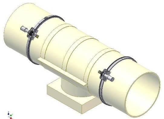
(A)            (B)                        (B)

   Figure 11. The Multi-Skip responses and the calculated average wall thickness as a result of minute local
   circumferential variations in wall thickness: dipping skips for a locally thicker (“strip”) part of the pipe at
position (A) and gradually bulging skips for locally thinner (“groove”) parts of the pipe at positions (B); the red
   & blue lines are the 0-degree wall thickness values from both sides of the support; graphs calculated with
                                 NTPLOT software from ESR Technology Ltd..

3.2 Flare Line at Shell UK’s Mossmorran Gas Plant

3.2.1 Description of the approach
From the experience gained with the inspection of the clamped saddle support locations of the
slug catcher at St Fergus Gas Plant, it was decided in 2011 to apply a similar approach to the
clamped saddle support locations of the Mossmorran 20”-48” flare line. The big difference
between the two structures is the wall thickness: the slug catcher is ~34 mm thick, while the
flare line has a nominal wall thickness of ~10 mm. This will cause the Multi-Skip signals to
come in shorter after each other. Since, overall, the Multi-Skip signal (wavelet) itself will
have the same length, this means that there is a chance that the skip signal will obscure any
local wall loss response coming in between two regular skip signals. Applying a broadband
(short) Multi-Skip wavelet is therefore crucially important.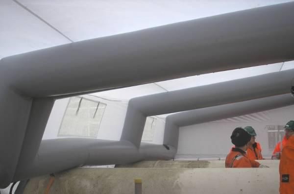
Despite the shorter probe-centre separation (PCS) in the case of the flare line (~600 mm
versus ~1600 mm for the slug catcher), the smaller wall thickness caused the ultrasound to
skip more times between the source and receiver transducers. Especially in case that the
reflecting surfaces are rough because of general wall loss, this will result in a lower amplitude
of the detected skip signals, which may even get lost in the noise. In order to assess general
wall loss despite of surface roughness, it was decided to combine Multi-Skip inspections with
CHIME inspections. CHIME signals [2] are better suitable to travel along rough surfaces and
in the case of an extended area of wall loss, they will still be able to indicate a degree of
degradation, while the Multi-Skip signals are lost. If a local area of wall loss is present, the
CHIME signals won't always be able to detect that, yet the Multi-Skip signals will be very
sensitive to that. Hence, CHIME was applied to identify (the degree of) general wall loss,
while Multi-Skip is applied to detect (and size) local wall loss.
Pipe diameters included in the scope covered 24”, 30”, 36”and 48”. All wall loss of 3.5mm or
more was considered intolerable according to the flare line specification. Wall loss of 3mm or
more was designated to be classified as “significant”. The ultrasonic screening inspection by
applying a combination of CHIME and Multi-Skip techniques was performed by Sonomatic
Ltd with the use of the same automated scanning set-up as used for the St Fergus slug catcher
(figure 8). The total number of clamped saddle supports inspected was 259. The same type of
sensitivity and scanning accuracy requirements were applied as in the slug catcher case.

3.2.2 Multi-Skip inspection results from the Mossmorran flare line
The semi-quantitative CHIME inspection results were classified in three degrees of wall loss:
30%. This classification in terms of general wall loss was governing in
ranking the supports on priority for follow-up inspection (radiography, lifting). The Multi-
Skip inspection results were analysed for the presence of local (diameter 30%, meaning more than 3 mm wall

                                                        CHIME                             Multi-Skip

 Figure 12. Picture of the pipe in the scan range around 450 mm after clamp removal and CHIME data with the
 area classified as >30% wall loss and corresponding Multi-Skip data (arrows indicate ~1 mm wall loss areas).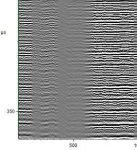
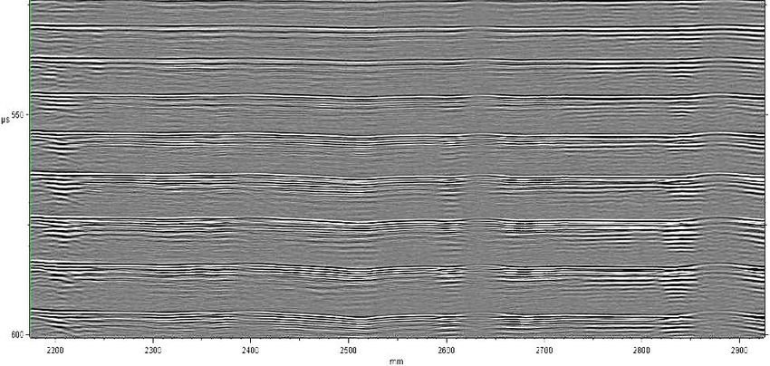
Figure 13. Full circumferential Multi-Skip scan data with local wall loss responses indicated by the arrows;
                             longitudinal welds are located at ~700 mm and ~2550 mm.

loss) is slightly overestimated. Analysis of the Multi-Skip responses at the same scan range
resulted in a measured maximum of 2 - 2.5 mm wall loss. This is in fair agreement with the
actual condition, because the Multi-Skip technique measures accumulative wall loss (1 mm at
both sides).
In some cases, good quality Multi-Skip data revealed local wall loss indications, which were
not detectable by CHIME . An example is shown in figure 13. These local wall loss responses
correspond to approximately 40-50% wall loss. Where the skip signal is not interrupted, this
indicates that the arc-type of responses originate from very local wall loss areas, which have
only been hit once by the regular Multi-Skip signal (so, no over-sizing expected).

4. Conclusions

The ultrasonic Multi-Skip inspection technique has made a modest entry in the world of
advanced ultrasonic inspection methods. As an intermediate-range inspection technique, it has
been shown that the technique is particularly useful for the inspection of pipes at clamped
saddle support locations. Multi-Skip inspections were done on 20”- 48” diameter pipe of 34
mm or 9.5 mm wall thickness. Although sensitivity and accuracy requirements are
challenging, it has been shown that scanning equipment can be applied to meet those
requirements in the field. It has been shown that very small general wall thickness variations
(0.1-0.4 mm), originating from the pipe fabrication process, can be detected by Multi-Skip. In
addition to that, accurate local wall loss values can be obtained from Multi-Skip responses. In
the presence of thicker (fresh) paint layers and over extended (corroded) areas with rough
surfaces the Multi-Skip technique is not so successful. The paint layer causes excessive
“ringing” of the Multi-Skip signal and makes the detection of local wall loss indications
impossible. Extended rough surface areas cause scattering of the Multi-Skip signal, indicating
the presence of corrosion, yet resulting in a loss of the Multi-Skip signal at the receiver end.
Despite certain limitations, the Multi-Skip inspection technique, with its high sensitivity to
local wall loss, appears to be a welcome addition to the currently available Guided-Wave and
CHIME inspection methods for inaccessible locations, like clamped saddle supports.

References

1.      S F Burch, N J Collett, S Terpstra & M V Hoekstra, 'M-skip: A quantitative technique
        for the measurement of wall loss in inaccessible components', Insight - Non-Destructive
        Testing and Condition Monitoring, Volume 49, No 4, pp 190-194(5), April 2007.
2.      F Ravenscroft, R Hill, C Duffill & D Buttle, „CHIME – A New Ultrasonic Method for
        Rapid Screening of Pipe, Plate and Inaccessible Geometries‟, Proceedings of the 8th
        ECNDT, European Conference on Nondestructive Testing Barcelona, 1998.
You can also read