Process-Control Computer System
←
→
Page content transcription
If your browser does not render page correctly, please read the page content below
I

Process-Control Computer System

                           LIST OC.39C JANUARY. lPdl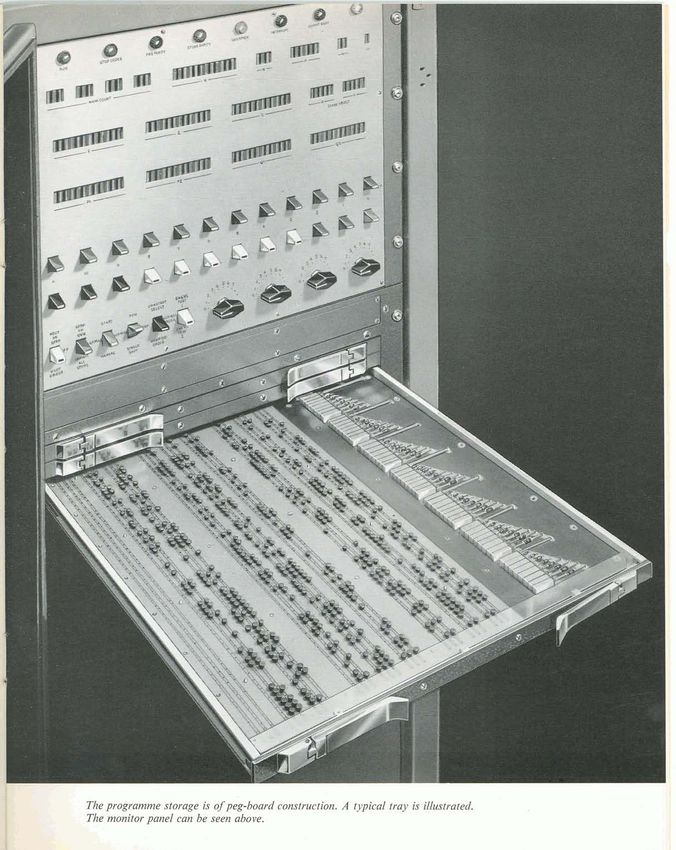
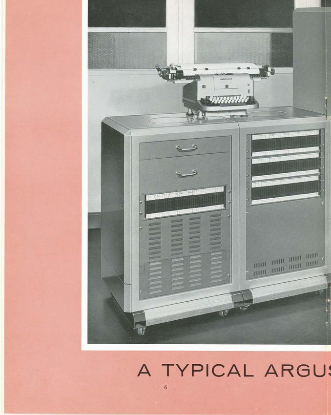
The Basic Argus Computer.

"Argus, the all-seeing, had a
hundred eyes which slept in turns, so that
he was at all times awake."
Ferranti ARGUS
Process-Control Computer System
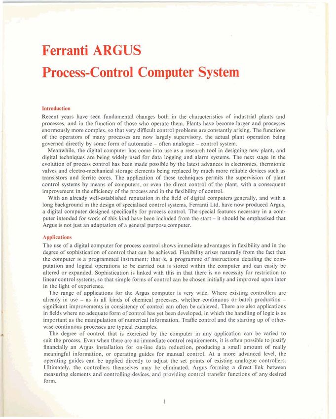
Introduction
Recent years have seen fundamental changes both in the characteristics of industrial plants and
processes, and in the function of those who operate them. Plants have become larger and processes
enormously more complex, so that very difficult control problems are constantly arising. The functions
of the operators of many processes are now largely supervisory, the actual plant operation being
governed directly by some form of automatic - often analogue - control system.
Meanwhile, the digital computer has come into use as a research tool in designing new plant, and
digital techniques are being widely used for data logging and alarm systems. The next stage in the
evolution of process control has been made possible by the latest advances in electronics, thermionic
valves and electro-mechanical storage elements being replaced by much more reliable devices such as
transistors and ferrite cores. The application of these techniques permits the supervision of plant
control systems by means of computers, or even the direct control of the plant, with a consequent
improvement in the efficiency of the process and in the flexibility of control.
With an already well-established reputation in the field of digital computers generally, and with a
long background in the design of specialised control systems, Ferranti Ltd. have now produced Argus,
a digital computer designed specifically for process control. The special features necessary in a com-
puter intended for work of this kind have been included from the start - it should be emphasised that
Argus is not just an adaptation of a general purpose computer.
Applications
The use of a digital computer for process control shows immediate advantages in flexibility and in the
degree of sophistication of control that can be achieved. Flexibility arises naturally from the fact that
the computer is a programmed instrument; that is, a programme of instructions detailing the com-
putation and logical operations to be carried out is stored within the computer and can easily be
altered or expanded. Sophistication is linked with this in that there is no necessity for restriction to
linear control systems, so that simple forms of control can be chosen initially and improved upon later
in the light of experience.
The range of applications for the Argus computer is very wide. Where existing controllers are
already in use - as in all kinds of chemical processes, whether continuous or batch production -
significant improvements in consistency of control can often be achieved. There are also applications
in fields where no adequate form of control has yet been developed, in which the handling of logic is as
important as the manipulation of numerical information. Traffic control and the starting up of other-
wise continuous processes are typical examples.
The degree of control that is exercised by the computer in any application can be varied to
suit the process. Even when there are no immediate control requirements, it is often possible to justify
financially an Argus installation for on-line data reduction, producing a small amount of really
, meaningful information, or operating guides for manual control. At a more advanced level, the
operating guides can be applied directly to adjust the set points of existing analogue controllers.
Ultimately, the controllers themselves may be eliminated, Argus forming a direct link between
measuring elements and controlling devices, and providing control transfer functions of any desired
form.
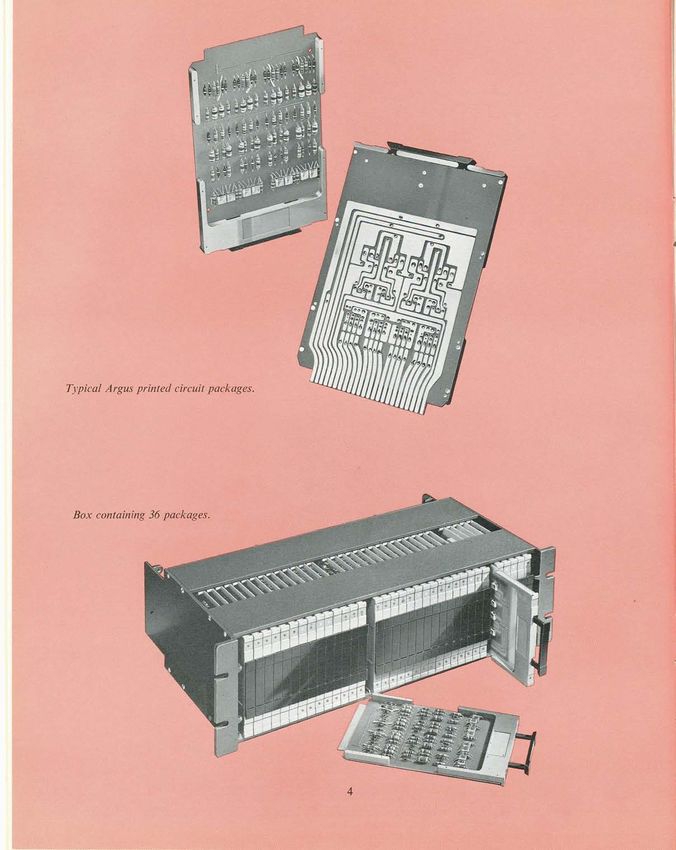
Argus can be used at any of these levels, or can progress from one to another without the expense
of replacing each successive installation. By suitable time-sharing techniques, a single computer can
often serve a number of independent processes.

r o r those who are unfamiliar with digital computers, a word of explanation may be helpful. Any
computation that has to be performed must be broken down into a programme, which is a sequence
of elementary instructions, each of which is usually an arithmetical operation such as addition or
multiplication. The programme is stored within the computer, which can therefore repeat (or altern-
atively ignore) some sections as required; the decision for such a repetition is made, for example, on
the result of a computation. Writing programmes for any computer is necessarily a specialised skill,
and Ferranti Ltd. employ a large staff of programmers to advise and help customers at any level.
   Numbers within the computer are held in binary form, so that successive digits represent powers of
2, as opposed to powers of 10 in decimal notation. Each binary digit or "bit" can only have two values,
0 or 1 (contrast 0 to 9), which is convenient for purposes of design. Temporary storage is provided for
intermediate results of computations, one number occupying one location in the store. The greater
the number of bits, the more accurate the computer: one decimal place corresponds to about three bits.
Each instruction is stored in the computer as a set of binary numbers which are decoded before the
instruction is obeyed.     ,,

The Argus Corn]               .   .
In designing a computer for process control, the following requirements have to be considered:
   (1) Reliability. It has already been remarked above that very high reliability is an essential feature
in process control.
   (2) Ease of programming. This is a desirable feature in any digital computer, and depends upon the
order code.
   (3) Timing. Some method of ensuring the exact timing of operations within the computer is vital,
since many external devices depend on this, and also because the theory of control requires regular
sampling of inputs.
   (4) Suitable accuracy and speed. These two conflict with one another to some extent and a com-
promise must be carefully chosen.
   (5) Input and output facilities. One of the principal differences between a general-purpose computer
and a process control computer is that the former uses comparatively few input and output devices,
whereas the latter must also expect to take readings from many instruments and send signals to many
control points.
   Argus has been designed to satisfy all these conditions. A complete specification is given at the end
of this pamphlet, and is discussed in greater detail under the separate headings below.

In order to achieve the reliability required, the standards of design and engineering are very high.
The circuitry employs only solid state devices and is based on a small number of elementary functions.
Unit construction, employing printed circuit cards of a few standard types, forms the basis of the
construction; these are plugged into connectors in boxes, whose own interconnections are made
by wrapped joints and wire loom held in special channel sections. The entire computer conforms with
AID standards, to satisfy the exacting demands of certain military applications.
   The standard of reliability is so high that preventive maintenance is not envisaged for most applica-
tions. When failure does occur, a diagnostic programme can be used to assist in locating the fault,
and the relevant package can be replaced from a small stock of spares. Measures can also be taken to
guard against breakdown during operation; this is arranged by performing a special test computation
at regular intervals and automatically taking alarm action if it is not completed satisfactorily.
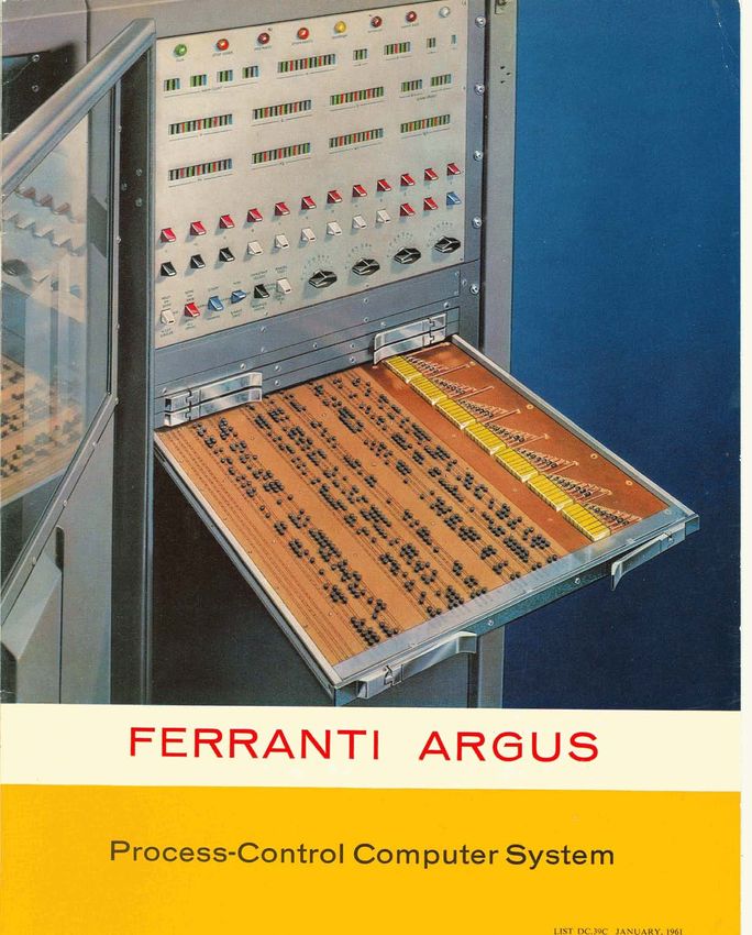
The programme storage is of peg-board construction. A typical tray is illustrated.
The monitor panel can be seen above.
A particular feature that distinguishes the design of Argus from that of other digital computers is
the provision of separate storage for programme and numerical information. The reliability of the core
store is adequate for information which changes in the course of the calculation so that errors which
might conceivably arise do not normally have any far reaching effects. A further safeguard is the
provision of an additional "parity" bit on each storage location which gives an indication when failure
occurs. For the programme, which is not changed during operation and requires an even higher
standard of reliability, a pegboard system is provided. Instructions are pegged up in their binary form
in trays with ferrite pegs, giving the necessary response by means of currents induced in wiring printed
on the trays. Orders can only be altered, therefore, by inserting or removing pegs from the trays;
accidental alteration is impossible, as the pegs are locked in position by putting the trays into their
rack in the computer. A parity check is provided on the pegboards also.

hogramming
The order code for Argus, given at the end of the pamphlet, has been based on that for Pegasus,
which has proved itself convenient in use over many years. The main differences are the simplifications
introduced by using entirely fast-access core storage for numbers, and the extra provisions for working
with double-length numbers where greater accuracy is needed (see below). The amount of core storage
provided makes the organisation of programmes particularly easy, but where very large amounts of
data have to be handled a magnetic drum can also be supplied. Constants of a permanent nature can
be stored interchangeably with programme on the pegboards.
The pegging of programmes on to trays can be made easier by use of an interpretative routine
prepared for Pegasus, which will assemble a complete programme from sections, and print a pegging
layout. Punched cards can also be used to cover the trays, pegs being inserted in exposed holes.

','he 1 4 ~that
            t   certain orders take a variable length of time (particularly multiplication and division),
and the uncertainty introduced by conditional jumps, make it imperative to include an independent
device for the exact control of timing, particularly of input and output. In preference to a clock,
treated as a special input, Argus is provided with a timer interrupt scheme as being more flexible and
convenient in use. A special register holds an integer which is reduced by 1 every two computer word
times (40 microseconds) independently of the other operations being carried out by the programme.
When it becomes zero, the programme sequence is broken and returned to the orders at the beginning,
which may be terminated by a return order, taking control back to the main programme at the point
of interruption.
    The integer can be reset by programme to any value between 1 and 212, giving interrupt periods of
up to 160 milliseconds. Several different interrupt periods operating simultaneously can be arranged
by suitable programming, using counters held in the core store; this technique also permits the exten-
 sion of interrupt periods to any desired length.

The basic word length of Argus gives an accuracy of 1 part in 2048. This is sufficient to allow for an
overall accuracy for simple computations which compares favourably with industrial instrumentation.
Where longer computations are involved, round-off errors may build up and cause deterioration in
overall accuracy; provision is therefore made for working with equal ease to an accuracy of about
1 part in 8 x lo6. Higher accuracies can be obtained by means of special programming techniques.
  The times taken for the various functions in the order code are detailed in the specification at the
end of the pamphlet (Table 3). They have been chosen to meet the most exacting requirements, found
mainly in military applications, and the overall speed is ample for control purposes in industrial
processes, where the shortest reaction times normally encountered are of the order of seconds.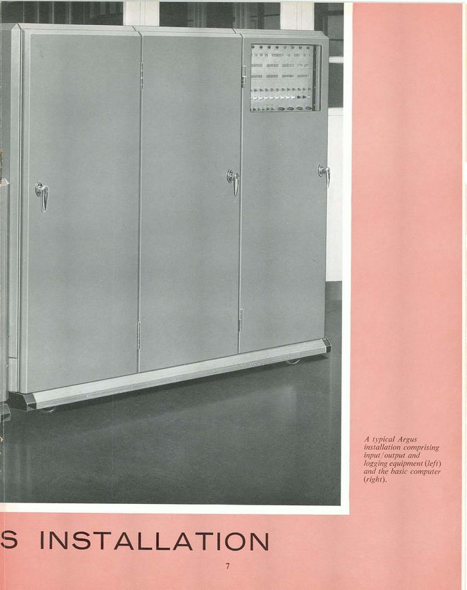
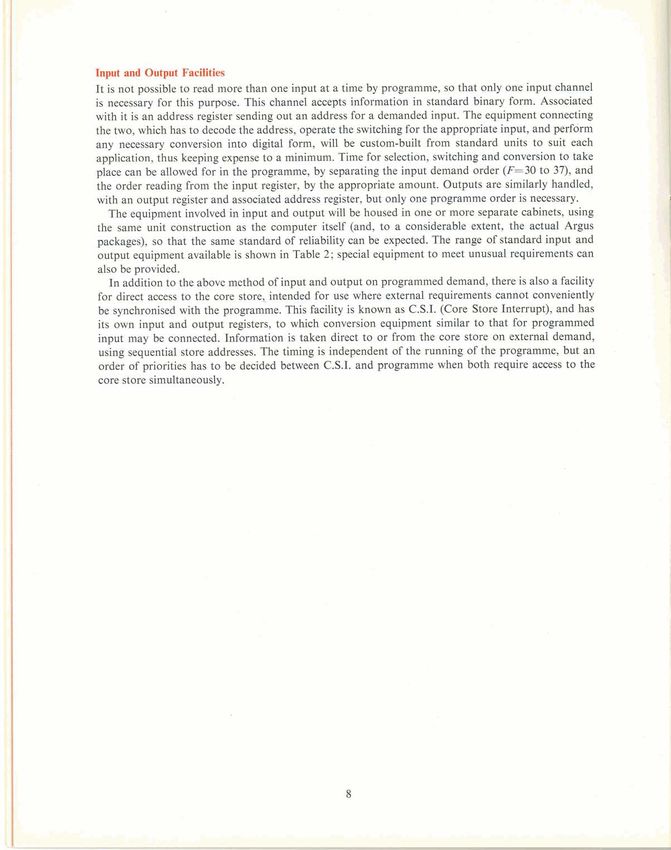
Input and Outgot Fadlfties
It is not possible to read more than one input at a time by programme, so that only one input channel
is necessary for this purpose. This channel accepts information in standard binary form. Associated
with it is an address register sending out an address for a demanded input. The equipment connecting
the two, which has to decode the address, operate the switching for the appropriate input, and perform
any necessary conversion into digital form, will be custom-built from standard units to suit each
application, thus keeping expense to a minimum. Time for selection, switchmg and conversion to take
place can be allowed for in the programme, by separating the input demand order (F=30 to 37), and
the order reading from the input register, by the appropriate amount. Outputs are similarly handled,
with an output register and associated address register, but only one programme order is necessary.
   The equipment involved in input and output will be housed in one or more separate cabinets, using
the same unit construction as the computer itself (and, to a considerable extent, the actual Argus
packages), so that the same standard of reliability can be expected. The range of standard input and
output equipment available is shown in Table 2; special equipment to meet unusual requirements can
also be provided.
   In addition to the above method of input and output on programmed demand, there is also a facility
for direct access to the core store, intended for use where external requirements cannot conveniently
                                                                                                         1
be synchronised with the programme. This facility is known as C.S.I. (Core Store Interrupt), and has
its own input and output registers, to which conversion equipment similar to that for programmed
input may be connected. Information is taken direct to or from the core store on external demand,
using sequential store addresses. The timing is independent of the running of the programme, but an
 order of priorities has to be decided between C.S.I. and programme when both require access to the
core store simultaneously.
C~mgJlteE
$gartJlrattos (Excluding Input-Output Cabinet)
Tm
Number system: Fixed-point binary.
Mode of operation : Serial-parallel.
Word length: Numbers, 12 or 24 bits including sign; instructions 24 bits; 1 parity checking bit on numbers and orders.
Addressing: Modified single address; multiple accumulators.
Storage
Numbers: Immediate access ferrite core matrix, capacity up to 3072 words (12 bits+parity) in units of 1024.
Optional extra MD5 magnetic drum, capacity 50,000 words.
Instructions: Immediate access induction-type pegboard, capacity up to 4096 words (24 bits+parity)
in units of 1024.
SpclcfrUBm
Timer interrupt, breaking control sequence at times determined by programme.
Input and output by programmed random selection or direct sequential access to store (C.S.I.).
~Colrstraebln
Cabinet: Dust-sealed, 72"x 60"x 24".
Components: Approximately 4000 transistors and 20,000 diodes depending on capacity; no thermionic valves.
Wiring: Printed circuit plates (15 types) mounted in boxes; interconnections by wrapped joint and wire loom.
Pawm (E-gdwr
Approximately 2 kVA. Normal supplies are 240 V, 50 c/s, 3-phase, but other supplies may be used.
A w - *
This is similar for both input and output, and uses standard Argus logical packages. Any number of input or output
addresses can be decoded, up to the capacity of the computer. In many cases, the h a 1 stage of the decoding is
combined with providing drive to the switches.
mw IalJats
Switching systems for binary information from digitisers and single bit inputs from on-off switches.
Decimal switches.,for manual alteration of constants.
Decimal-to-binary converter, for use where programmed conversion is inconvenient.
Paper tape reader.
Magnetic tape reader.
W a g n e Inputs
Solid-state switching, giving maximum speed and reliability.
Relay switching, for very low-level signals.
Analogue-to-digital converter, giving 10 bits (0.1 %) accuracy in 44 microseconds.
D.C. amplifier, for amplifying low-level signals prior to conversion, and smoothing where necessary.
mw*mb
Drive gates for relays and corn01 solenoids.
Decimal display, giving visual operating guides.
Binary-to-decimal converter, for use where programmed conversion is inconvenient.
Paper tape punch.
Magnetic tape output.
Electric typewribr or other printing device
-0-
Digital-to-analogue converter, producing analogue control signals or drive for chart recorders.TABLE 3
. .
an i
. ,
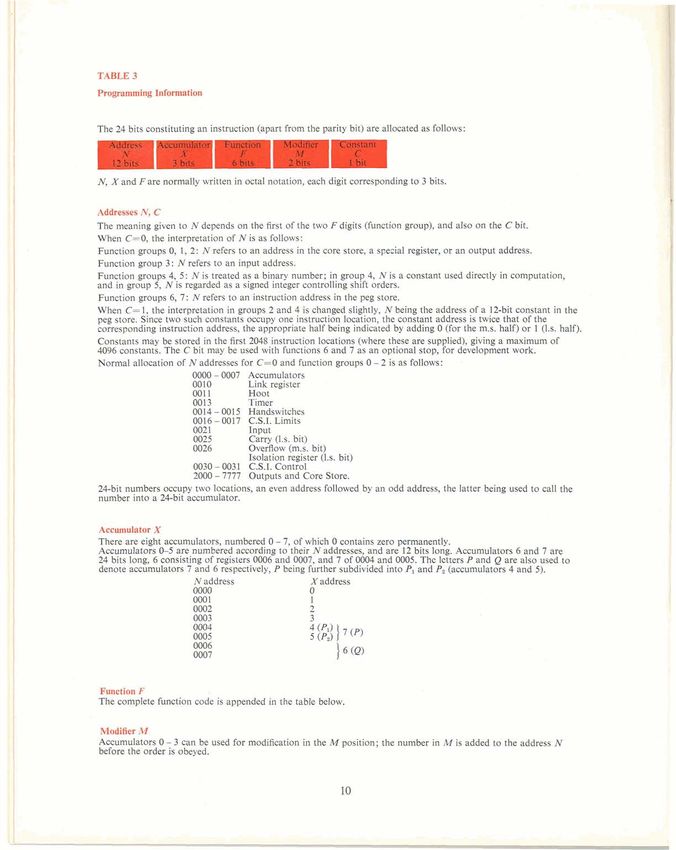
fron ' ity bit) are allocated as follows:
N, X and F a r e normally written in octal notation, each digit corresponding to 3 bits.
Addresses N,C
The meaning given to N depends on the first of the two F digits (function group), and also on the C bit.
When C=O, the interpretation of N is as follows:
Function groups 0, 1, 2: N refers to an address in the core store, a special register, or an output address.
Function group 3 : N refers to an input address.
Function groups 4, 5 : N is treated as a binary number; in group 4, N is a constant used directly in computation,
and in group 5, N is regarded as a signed integer controlling shift orders.
Function groups 6, 7: N refers to an instruction address in the peg store.
When C= 1, the interpretation in groups 2 and 4 is changed slightly, N being the address of a 12-bit constant in the
peg store. Since two such constants occupy one instruction location, the constant address is twice that of the
corresponding instruction address, the appropriate half being indicated by adding 0 (for the m.s. half) or 1 (1s. half).
Constants may be stored in the first 2048 instruction locations (where these are supplied), giving a maximum of
4096 constants. The C bit may be used with functions 6 and 7 as an optional stop, for development work.
Normal allocation of N addresses for C=O and function groups 0 - 2 is as follows:
0000 - 0007 Accumulators
0010 Link register
001 1 Hoot
0013 Timer
0014 - 0015 Handswitches
0016 - 0017 C.S.I.Limits
0021 Input
0025 Carrv (1s. bit)
0026 0veaow (mi. bit)
Isolation register (1.s. bit)
0030 - 0031 C.S.I. Control
2000 - 7777 Outputs and Core Store.
24-bit numbers occupy two locations, an even address followed by an odd address, the latter being used to call the
number into a 24-bit accumulator.
There are eight accumulators, numbered 0 - 7, of which 0 contains zero permanently.
Accumulators 0-5 are numbered according to their N addresses, and are 12 bits long. Accumulators 6 and 7 are
24 bits long, 6 consisting of registers 0006 and 0007, and 7 of 0004 and 0005. The letters P and Q are also used to
denote accumulators 7 and 6 respectively, P being further subdivided into PIand P, (accumulators 4 and 5).
N address X address
0000 0
0001 1
0002 2
0003 3
Function F
The complete function code is appended in the table below.
Modffler M
Accumulators 0 - 3 can be used for modification in the M position; the number in M is added to the address N
before the order is obeyed.Lower case letters indicate contents of the address or accumulator, denoted by corresponding capital letters before
the order is obeyed,Values after the order is obeyed are indicated by a prime (3. Nand n refer to contents of N address
locations after mod~fication.In orders of group 5, N is regarded as an integer.
00 x'= n 10 n'= x
01 x'= x n
02 x'= -n
+ 11 n 7 = n + x
12 n'= - x
03 x'= x - n 13 n'= x - n
04 x'= n - x 14 n'= n - x
05 x'= x & n 15 n)= n & x
06 x'= +n 16 nr= rt$x
07 17
12-bit numbers (X=O to 5) 24-bit numbers (X=6 or 7)
20 p'= n . x (pq)'= n ,x
21 p'= n.x+2-" &Y= n.x+2+&
22
23
24 pA,+2-11~L,
n
0,n
IA <
n
q1+2-aaZ= @I,O~$ 0, down if N < 0).
52 p'=p.2N, X=4, or (pq)'=(pq).2N, if X=7, unrounded.
53 Shiftp, if X=4, or (pq) if X=7, logically Nplaces.
54 p'= p.2fi, x'= x - p
55 (pq)'= (pq).2P, x'= x -
56 $sp'Ferrant i
range of
Computer
Enquiries to
FERRANTI LTD
LONDON COMPUTER CENTRE
68-71 NEWMAN STREET, LONDON W1
Telephone MUSeum 5040
or WYTHENSHAWE, MANCHESTER 22
Telephone MERcury 5291
or 21 PORTLAND PLACE, LONDON W1
Telephone LANgham 921 1
Works WEST GORTON, MANCHESTER 12
Telephone EASt 1301
----
LIST DC39C Q Ferranti Ltd. 1961
Printed in England
JANUARY, 1961You can also read