Installation / User Manual - APsystems ECU-C Energy communication unit with advanced functions - APsystems USA
←
→
Page content transcription
If your browser does not render page correctly, please read the page content below
Installation / User Manual
   APsystems ECU-C Energy communication unit
                     with advanced functions
                                               Rev 3.0

                              © All Rights Reserved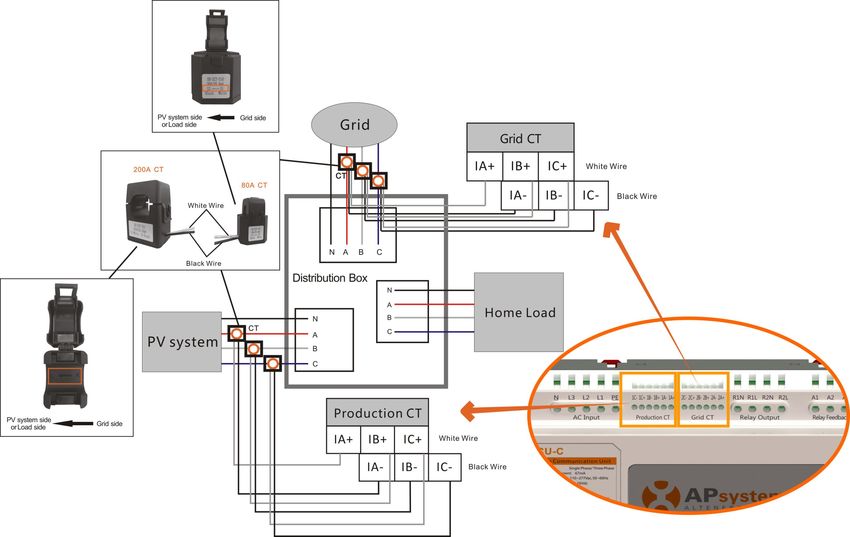
Table of Contents
Important Safety Instructions................................................................................... 2
1.Introduction............................................................................................................ 3
2.Interface Explanation............................................................................................. 4
       Interface Layout............................................................................................................... 4
       2.1 AC Input Port..............................................................................................................5
       2.2 DC Input Port..............................................................................................................5
       2.3 RJ45 Ethernet Network Port...................................................................................... 5
       2.4 RJ45 Signal(Only for Australia)............................................................................. 5
       2.5 AP............................................................................................................................... 6
       2.6 Power......................................................................................................................... 6
       2.7 USB Interface............................................................................................................. 6
       2.8 Reset.......................................................................................................................... 6
       2.9 LED............................................................................................................................. 6
3.Hardware Installation.............................................................................................7
       3.1 Preparation................................................................................................................ 7
       3.2 Selecting an Installation Location for the ECU-C........................................................7
       3.3 Cable Connections..................................................................................................... 9
       3.4 RJ45 Signal connection.............................................................................................. 9
       3.5 Internet Connection...................................................................................................9
       3.6 Current transformer interface................................................................................. 11
       3.7 Contactor connection.............................................................................................. 12
4.Basic Operation.................................................................................................... 13
       4.1 Restore the factory set operation............................................................................ 13
5. ECUAPP................................................................................................................ 14
       5.1 Connecting to the ECU-C via the Local Wireless......................................................14
       5.2 Add UID.................................................................................................................... 15
       5.3 Delete UID................................................................................................................15
       5.4 Homepage................................................................................................................15
       5.5 Data.......................................................................................................................... 16
       5.6 Settings.....................................................................................................................18
       5.7 EMA Registration function....................................................................................... 23
6.Local Network Interface....................................................................................... 25
       6.1 Connecting to the ECU-C via the Local Wireless......................................................25
       6.2 Home Screen............................................................................................................25
       6.3 Real-time Data Screen..............................................................................................27
       6.4 Administration Screen..............................................................................................27
       6.5 Advanced Screen......................................................................................................30
7.Remote ECU-C Management (EMA).................................................................... 32
       7.1 ECU-C Configuration/ECU-C Status Page................................................................. 33
       7.2 Setting the ECU-C Time Zone...................................................................................34
       7.3 Managing Inverter IDs and Updating the Inverter ID List........................................34
8.Technical Data...................................................................................................... 36

                                                                                  ECU-C Installation/User Manual                            1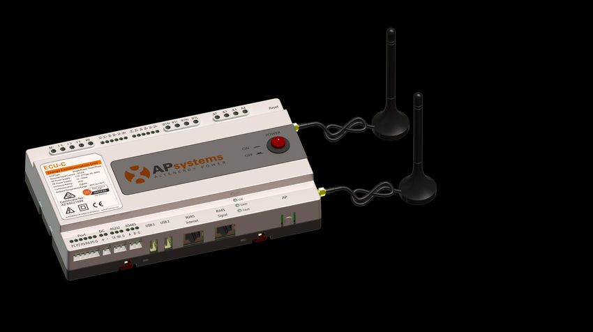
Important Safety Instructions

Symbols replace words on the equipment, on a display, or in
manuals

             Trademark.

             Caution, risk of electric shock.

             Equipment protected throughout by double insulation or
             reinforced insulation

             CE mark is attached to the solar inverter to verify that the unit
             follows the provisions of the European Low Voltage and EMC
             Directives.
             Person adequately advised or supervised by an electrically
             skilled person to enable him or her to perceive risks and to avoid
             hazards which electricity can create. For the purpose of the
             safety information of this manual, a "qualified person" is
Qualified    someone who is familiar with requirements for safety,
personnel    refrigeration system and EMC and is authorized to energize,
             ground, and tag equipment, systems, and circuits in accordance
             with established safety procedures. The inverter and endues
             system may only be commissioned and operated by qualified
             personnel.

                                            ECU-C Installation/User Manual    2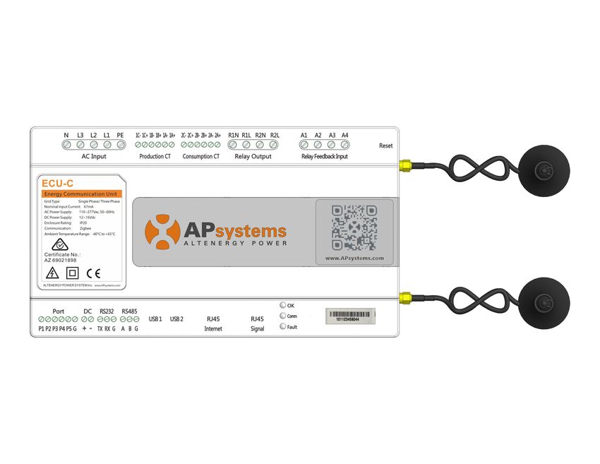
1.Introduction
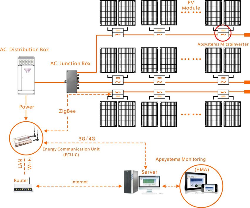
The APsystems Energy Communication Unit (ECU-C) is the information gateway
for our microinverters. The unit collects module performance data from each
individual microinverter and transfers this information to an Internet database in
real time. Through the APsystems Energy Monitoring and Analysis software, the
ECU-C gives you precise analysis of each microinverter and module in your solar
installation from any web-connected device. The ECU-C’s integrated http web
server offers the simplest and most flexible network integration of any data logger
on the market. The user-friendly browser-based interface lets you access your solar
array in seconds.
Features
Collects individual module and microinverter statistics
Remote communication
Requires no additional wiring
Applicable commercial system
The APsystems Microinverter is used in utility-interactive grid-tied applications,
and is made up of three key elements:
APsystems Microinverter
APsystems Energy Communication Unit (ECU-C)
APsystems Energy Monitoring and Analysis (EMA) web-based
monitoring and analysis system
Figure 1
ECU-C Installation/User Manual 3
2.Interface Explanation
Interface Layout
The ECU-C interface includes, (figure 2)from left to right, are AC Input、
Production CT、Grid CT、Relay Output、Relay Feedback Input、Reset.

(figure 3)from left to right, are Port、DC、RS232、RS485、USB1、USB2、RJ45、
Internet、RJ45 Signal、AP.

(figure 4)from left to right, are antenna(Zigbee)、antenna(Wifi).
  Reset     Relay Feedback Input   Relay Output   Grid CT   Production CT   AC Input

                                                                                       Figure 2
Port   DC    RS232 RS485    USB1 USB2     RJ45 Internet     RJ45 Signal       AP

                                                                                       Figure 3

Antenna(Zigbee)                         Antenna(Wifi)

                                                                                       Figure 4

                                                     ECU-C Installation/User Manual          4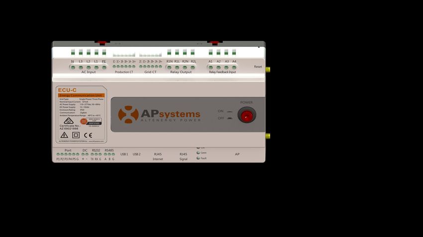
2.Interface Explanation

2.1 AC Input Port
The AC Input port connects power through the power line.If only single-phase
power is needed, the L1 must be connected.
                                L1         L2            L3          N            PE
       Three Phase               √           √            √          √             √
       Single Phase              √           ×            ×          √             √

     The AC input power should be assembled with disconnector(e.g. when the
     current is bigger than 1A, the disconnector should be operated).

2.2 DC Input Port
The DC Input port connects power through the 16V DC power line.
2.3 RJ45 Ethernet Network Port
The ECU-C allows the user to communicate with the EMA, or log in to the
ECU-C's local page in the absence of the wired LAN and WLAN, to set up the
system and view the system data via Ethernet network port.

  Ethernet cable connection is recommended for stable communication.

2.4 RJ45 Signal(Only for Australia)
The RJ45 Signal is designed for DRM0/5/6/7/8, it should be connected by RJ45
connector in the package otherwise the inverters will not work.

  Please do not plug out the RJ45.

                                                          Power

                                                          Led

                                                       RJ45 Signal

                                                                                  Figure 5

                                                 ECU-C Installation/User Manual         5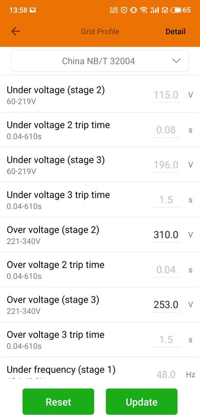
2.Interface Explanation

2.5 AP
Press the AP button to turn on AP. Then the ECU can be scanned by phone. You
can press the button again to turn off AP. If you don't turn off AP, ECU will turn
off it automatically in one hour.

2.6 Power
Press the button, ECU will be powered on. Press the button again, the button
would bounce back and ECU will be powered off.

2.7 USB Interface
The USB interface is reserved.
2.8 Reset
Press the Reset button for three seconds or longer, and the ECU-C will
automatically return to the default settings.

   The historical power generation won't be cleared.

2.9 LED
The OK light will blink when ECU-C starts up, and it will keep on after
registering.
The Comm light will be on when the ECU-C connects to EMA.
The Fault light will be on when the ECU-C breaks down.

                                                ECU-C Installation/User Manual   6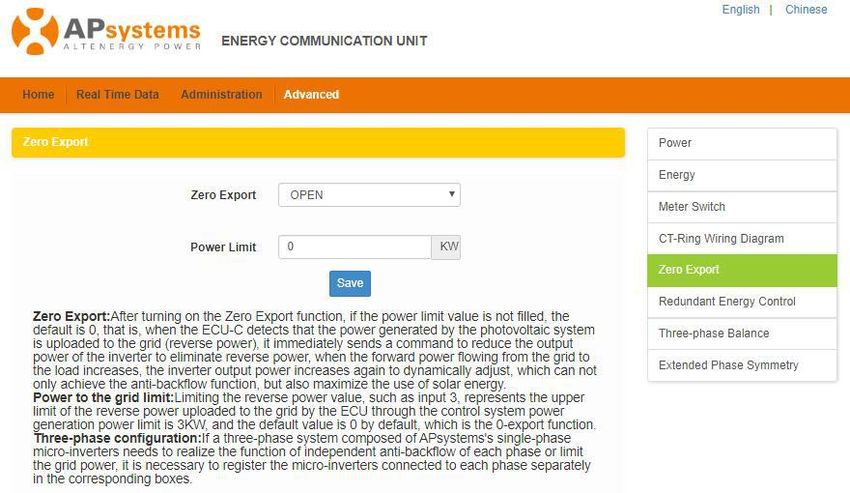
3.Hardware Installation
3.1 Preparation
Make sure you have the following components ready before beginning to install
the ECU-C:
A broadband Internet connection available for your use.
A broadband router with either a CAT5 Ethernet, or a wireless router .
A laptop with a web browser (to view the APsystems EMA online
monitoring application).
A pre-programmed ECU-C.
3.2 Selecting an Installation Location for the ECU-C
Choose a location that is electrically as close to the array as possible.
The ECU-C is NOT rated for outdoor use, so if installing outdoors near a
junction box or breaker panel, make sure you enclose it in an
appropriate weatherproof NEMA electrical box.
Avoid to install in the place children can not touch.
1) Power Distribution Cabinet Installation
If you use the energy communicator in power distribution cabinet:
Pull the four snap out with a screwdriver.
Figure 6
ECU-C Installation/User Manual 7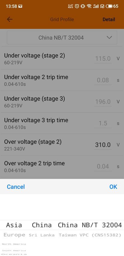
3.Hardware Instrallation
Attach two buckles below in the edge of the guide, press two buckles
above, then embed to the edge of the guide.
Figure 7
Do not put the antennas inside a metal box, that will block the signal.
If the roof is metal, please use this long cable antenna, and place it outside
or on roof.
2) Using a Wall Mount
When mounting the ECU-C to a wall, make sure to select a cool, dry indoor
location.
According to the size of an icon, The energy communicator is fixed on the
wall with two Wall screws or wall anchors.
Four M4 screws + spacers are fixed to the wall, and the punch sizes are
as follows:
110mm(4.3' ')
129.4mm(5' ')
Figure 8
ECU-C Installation/User Manual 8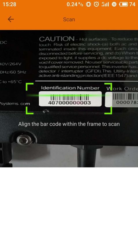
3.Hardware Installation
3.3 Cable Connections
Power Connection Port
Network port RJ45 Signal
Figure 9
Connect the power cable to the power connection port on the top of the
ECU-C.(Can also be DC power supply).
Connect the supplied LAN cable to the network port on the bottom of the
ECU-C.
3.4 RJ45 Signal connection
Plug the RJ45 connector in the package to RJ45 Signal port.
3.5 Internet Connection
There are three different approaches to connecting the ECU-C to the Internet:
Option 1: Direct LAN cable connection.
1) Make sure the LAN cable is connected to the network port on the bottom
of the ECU-C.
2) Connect the LAN cable to a spare port on the broadband router.
ECU-C Installation/User Manual 93.Hardware Installation
Figure 10
Option 2: Wireless Connection.
Use ECU-C internal WLAN (see Managing the WLAN Connection, pg. 23).
Option 3: Using a PLC bridge:
1) Make sure the LAN cable is connected to the network port on the bottom
of the ECU-C.
2) Connect the LAN cable to the “send” unit of the PLC bridge.
3) Connect a LAN cable from the “receive” unit of the PLC bridge to a spare
port on the broadband router (refer to the bridge users manual for
specific operating instructions).
Figure 11
The network cable in the package can be used to connect the ECU-C with
PC directly. One side is connected with the ECU-C and the other side is
connected with the PC. Then change the IP address and the network
mask to 192.168.131.1 and 255.255.255.0, respectively.
1. A PLC bridge uses the power line to communicate and requires both a
“send” and “receive” unit.
2. The quality and length of the LAN cable will affect the ECU-C
communication quality. You can use a Switch to enhance the
communication quality if necessary.
ECU-C Installation/User Manual 103.Hardware Installation
3.6 Current transformer interface
By installing Current Transformer(CT), the integrated meter in ECU-C can
measure the production&consumption power and energy. Please refer to the
picture.
It is mandatory to install the current transformer on production and
consumption side to get the anti-backflow function.
Anti-backflow function manages inverters one by one: it turns on/off each
inverter through zigbee communication,in order to get production inferior or
equal to consumption.
Figure 12
Please ensure that the ECU-C is in a power off state when installing the
transformer.APsystems can provide the current transformers, please
contact us or our distributors.
ECU-C Installation/User Manual 113.Hardware Installation
3.7 Contactor connection
ECU-C provides two contact driver signal interface, two-way contact signal
interface.
Interface Interface description
The first road contactor drives the output L, and is
R1L
connected with the power supply interface L1.
The first road contactor drives the output N, and is
R1N
connected with the power supply interface N.
Second road contactor driver output L, with the
R2L
power supply interface L1.
Second road contactor driver output N, with the
R2N
power supply interface N.
A1 A2 First contact feedback signal input, non polarity.
Second way contactor feedback signal input, non
A3 A4
polarity.
Figure 13
ECU-C automatic detection and judgment of the current power grid environment,
through the drive signal interface to control the opening or closing of the
contactor. The feedback signal interface and NO of contactor are often connected
to inform the ECU that the contactor is effectively closed.
ECU-C Installation/User Manual 124.Basic Operation
4.1 Restore the factory set operation
The following diagram shows the connetions on the bottom of APsystems the
ECU-C.
RESET
Figure 14
To restore the ECU-C’s factory settings, simply press the “Reset” button for three
seconds or longer. The unit will automatically return to its default settings.
ECU-C Installation/User Manual 135. ECUAPP
Please use mobile browser to scan the QR codes to download ECUAPP :
(iOS) (Android)
5.1 Connecting to the ECU-C via the Local Wireless
Open Wi-Fi setting in your smartphone, default no password.
Open the ECUAPP.
Check ECUAPP is connected to ECU-C in the Home page.
ECU-C Installation/User Manual 145.ECUAPP
5.2 Add UID
Click "Settings", select "ID Management", input the UID manually or
scan the UID by camera. If there is no need to modify, then click "SYNC"
to update the UIDs onto ECU.
5.3 Delete UID
Select the UIDs, click "DELETE" then click "SYNC". The UIDs selected
are deleted on the ECU-C.
5.4 Homepage
Click "Home" at the bottom of the page.
The information about systems info of ECU-C,
ECU-C ID, version , total number of
inverters, the number of connected
inverters, intraday power output, historical
power output and current system power shall
be displayed.
ECU-C Installation/User Manual 155.ECUAPP
Green light indicates the mobile phone is connected to the ECU-C.
Grey light indicates the mobile phone fails to connect to the ECU-C.
5.5 Data
5.5.1 Real Time Data
This page shall display the added inverter. According to different
models of inverter, each inverter would have the corresponding modules
displaying the real time power.
Click "Module", the detailed information of the inverter shall be
displayed, including inverter ID, PV module power, grid voltage,
frequency and temperature.
Green panel indicates the inverter is successfully connected.
Grey panel indicates the inverter is disconnected.
ECU-C Installation/User Manual 165.ECUAPP
5.5.2 Power
To This page displays the daily system power
curve. Click "Power" at the real time data page
to view the historical system power curve.
5.5.3 Power generation statistics
Press “Energy” at the real-time data page to
view the system power generation of the solar
system.
The statistics of power generation shall be displayed.
The energy histogram of current week:
ECU-C Installation/User Manual 175.ECUAPP
5.6 Settings
Click "Settings" and enter into the
"settings page".
5.6.1 Manage IDs
Please refer to 5.2 to add UID.
5.6.2 Grid Profile
User needs to select grid profile when
installing the system.
5.6.3 Inverter Signal Level
Show the direct communication quality
between each inverter and ECU.
If you select the wrong grid profile, the inverters will not work normally.
ECU-C Installation/User Manual 185.ECUAPP
Enter the Detail page, you can view the inverters’ parameters. Click
Read, ECU will get the parameters from inverters. You can swipe down
the ID list to view the result after about 5 minutes later.
5.6.4 Time management
Enter the page, the time of ECU-C shall be
displayed on the right side of the page.
Click "date" or "time" to modify.
Click "Sync time", APP will set the date and time
of the phone for ECU, user doesn't need to set
date and time manually.
ECU-C Installation/User Manual 195.ECUAPP
5.6.5 Manage the Network Connection
ECU-C's wired network setting has 2 options: automatically obtain an
IP address or use a fixed IP address.Obtaining an IP address
automatically means the router would distribute IP to ECU-C
automatically. When choose user fixed IP, users shall use the following
IPs.
5.6.6 Manage the WLAN connection
The page will show up ECU's wireless connection status. Click "Refresh"
button, the available SSID would show up.
Click the SSID and enter the password.
The ECU-C would restart after sending the password. Please reconnect
the ECU-C.
ECU-C Installation/User Manual 205.ECUAPP
After the password is sent, ECU-C will restart. Please reconnect to ECU-C.
5.6.7 WLAN PASSWORD
Used to modify the WiFi password of ecu-c. When setting, you need to
enter "old password" and "new password". If the user forgets the "old
password", you can reset the ecu-c hardware first to restore the WiFi
password to the initial password free state.
Enter "old password" and "new password", and click the "UPDATE"
button to complete the setting.
ECU-C Installation/User Manual 215.ECUAPP
5.6.8 Automatic System Check
This function detects the running status
of the system , click to see the
reason or reference solution for the
failure.
5.6.9 Inverter Connection Progress
User can see the connection progress of the
inverters, 100% means the connection is
finished.
5.6.10 Language
Select Language.
ECU-C Installation/User Manual 225.ECUAPP
5.6.11 Help
5.7 EMA Registration function
Register the inverters’ID into ECU on
ID Management screen. Make sure the
IDs have been synced to ECU.
ECU-C Installation/User Manual 235.ECUAPP
5.7.1 Scan ECU’s ID
Scan the ECU’s ID which is a 12 digits
number starting with a 2, then click
OK.
5.7.2 Create Customer
Connect your phone to internet instead
of to the ECU. Then enter the
information and click “Sync EMA”.
User name, password,city and
country/state are necessary.
ECU-C Installation/User Manual 246.Local Network Interface
6.1 Connecting to the ECU-C via the Local Wireless
1. Turn on the Wi-Fi function on PC or phone.
2. Scan the ECU ’s SSID which named “ECU-WIFI_XXXX” (the “xxxx”
refers to the last 4 numbers of the ECU-C ID), connect to the ECU-C’s
SSID. The first connection has no password.
3. Using a standard web browser on your computer, Enter the ECU ’s IP
172.30.1.1 into browser.
The ECU-C’s “splash” screen is displayed.
Figure 15
6.2 Home Screen
Select “Home” at the top of the page.
The Home Page is displayed.
Figure 16
ECU-C Installation/User Manual 256.Local Network Interface
ECU-C ID: This is a unique number that identifies this specific
ECU-C.
Lifetime Generation: Amount of power this system has generated during its
lifetime.
Last System Power: Amount of power the system was generating during its
last polling cycle.
Generation of
Current Day: Amount of power that has been generated during the
most current day.
Last connection to
Website: The last time the ECU-C checked into the central
APsystems EMA database.
Number of Inverters: Number of inverters that have programmed into the
ECU-C.
Last Number of
Inverters Online: Number of inverters that are checking in with the
ECU-C.
Current Software
Version: Current version of the firmware.
Current Timezone: Time zone that has been programmed into the ECU-C.
ECU-C Eth0 Mac
Address: Address of ECU-C’s LAN.
ECU-C Wlan0 Mac
Address: Address of the ECU-C’s internal WLAN.
Inverter Comm.
Signal Level: The communication strength between inverters and
ECU-C. The range is 1-5, the higher the better.
ECU-C Installation/User Manual 266.Local Network Interface
6.3 Real-time Data Screen
Figure 17
a) Real Time Data
To view the real-time system operation data statistics for your solar array, click
“Real Time Data” from the ECU-C home screen to navigate to the real-time data
screen.
b) Trend of system power
To view the system power of any period, click "Power" at the real-time data page.
c) Power generation statistics
Press “Energy” at the real-time data page to view the system power generation of
your solar array.
Performance data for the current week/month/year.
6.4 Administration Screen
Figure 18
ECU-C Installation/User Manual 276.Local Network Interface
a) Managing Inverter IDs
The inverter IDs must be programmed into the ECU-C for the ECU-C to
recognize the inverters. The ECU-C will NOT auto-sense the inverters.
Initial Programming of the ECU-C with the Inverter IDs.
The “Enter Inverter ID” window field will be blank if you have not yet
entered any of the inverter IDs.
Select “Administration” at the top of the page.The ID Management page is
displayed.
User can modify the ids in the text box to add, delete or replace ids.
Combine the above two steps when swapping out an inverter. Add the
new inverter, and Delete the old one. Remember to follow up with the
same process on the APsystems EMA because the ECU-C and EMA need
to be in sync with each other.
b) Grid Profile
User needs to select grid profile when installing the system.
If you select the wrong grid profile, the inverters will not work normally.
c) Changing the Date, Time Zone
It is critical for accurate power production reporting that the ECU-C is
programmed with the correct date, time, and time zone.
1) Select “Administration” at the top of the page.
2) Select “Date, Time, Timezone”.
3) Adjust the correct date in the “Date Time” field.
4) Select the correct time zone from the Time Zone pull down.
You can skip step 3 by selecting the correct time zone.
Selecting the correct time zone automatically updates both the date and
current time.
ECU-C Installation/User Manual 286.Local Network Interface
d) Changing the Language
Users can switch language between English and Chinese.
1) Select “Administration” at the top of the page.
2) Select “Language”.
3) Select the language from the Current Language pull down.
4) Press “Update”.
e) Managing the Network Connection
The default network connection setting for the ECU-C is “DHCP,” which allows
the ECU-C to automatically establish a connection assignment from the router.
The ECU-C can be assigned a static.
IP Address if the network design requires it.
1) Select “Administration” at the top of the page.
2) Select “Network Connectivity”.
3) Select “Obtain an IP address automatically”.
4) Press “Update”.
f) Managing the WLAN connection
The ECU-C can both work in two modes: WLAN and Local Wireless Access. In
WLAN mode, the ECU-C can connect to a router by Wi-Fi. In Local Wireless
Access mode, user’s phone or PC can connect to ECU-C to access local web.
Static IP mode and WLAN mode cannot be used at the same time.
WLAN mode
1) Select “Administration” at the top of the page.
2) Select “WLAN”, and click “WLAN” tab.
3) The ECU-C will display the available networks.
Select the button next to the available network that you wish to access
SSID, and a password entry field will be displayed below the network
name. Enter the password into the password entry field, then click
“Connect”.
4) If ECU-C has connected to the router, it will display the SSID and
IP address. Now you can connect by PC or phone to the router.
Enter the ECU-C’s IP (e.g., 192.168.4.119) into the browser to access
the local web.
Local Wireless Access mode
1) Scan the ECU-C’s SSID on PC and phone, and connect to ECU-C.
Enter the ECU-C’s IP 172.30.1.1(The IP is fixed) into browser to
access the local web.
ECU-C Installation/User Manual 296.Local Network Interface
2) On the page, you can modify SSID, Channel, Safe Type and
Password. If you don’t select the Safe Type, the Password is
hidden.
g) Firmware Update
Select the ECU-C upgrade package, and click OK to upgrade ECU-C firmware.
The upgrade package can be downloaded at www.APsystems.com.
6.5 Advanced Screen
Figure 19
a) Trend of power
To view the production power 、 consumption power and exported power of any
period, click "Power" at the "Advanced" page.
b) Energy statistics
Press "Energy" at the "Advanced" page to view the production energy ,
consumption energy and exported energy.
The energy statistics screen is displayed.
Performance data for the week/month/year.
c) Meter Switch
Once the meter display is turned on, ECU will refresh the meter data every 5
minutes.
d) CT-Ring Wiring Diagram
Please refer the pictures on the ECU's page to install CTs.
User needs to install six CTs in three-phase system, or install two CTs(1A,2A) in
single-phase system.
ECU-C Installation/User Manual 306.Local Network Interface
e) zero export
Figure 20
The zero export function could limit the power export to the grid. Users could
set the maximum export power when the zero export function is turned on.
After turning on the Zero Export function, if the power limit value is not filled,
the default is 0, that is, when the ECU-C detects that the power generated by
the photovoltaic system is uploaded to the grid (reverse power), it immediately
sends a command to reduce the output power of the inverter to eliminate
reverse power, when the forward power flowing from the grid to the load
increases, the inverter output power increases again to dynamically adjust,
which can not only achieve the anti-backflow function, but also maximize the
use of solar energy.
f) Redundant energy control
The redundant energy control function could make the electric equipment to use
redundant energy. If the redundant power is more than power limit, ECU-C will
close the relay.
g) Three-phase balance
Three Phase Balance function could limit the current between each phase less
than 16A. User needs to click the "three phase configure" button to bind the
inverters into corresponding phase.
h) Extended Phase Symmetry
When using APsystems single-phase micro-inverse to form a three-phase system,
if one phase's AC breaker is tripped or swtiched off, the inverters on this phase
will shutdown, and then the inverters on the other 2 phases also will be turned
off, until the AC breaker is turned on, all the inverters will start again.
ECU-C Installation/User Manual 317.Remote ECU-C Management (EMA)
The ECU-C has been designed with remote connect functionality. You can access
this remote functionality through the APsystems Energy Monitoring & Analysis
(EMA) website, using your installer login credentials. Changes made remotely
through the EMA do not take effect until the ECU-C’s next reporting cycle.
The ECU-C must first be installed with Internet connectivity.
The ECU-C remote functionality allows you to do the following:
Set Time Zones
Manage Inverter IDs
There are additional ECU-C functions available but the instructions are not
outlined in this document. If you need to access one of the following features,
please contact APsystems Technical Support:
Change system parameters
Turn the inverters ON and OFF
Reset GFDI
Reset Power Settings
This section of the documentation assumes you have a working
knowledge of the APsystems EMA.
1) Log onto your APsystems EMA account.
Your Customer List within the Installer Portal is displayed.
2) Select the customer’s ECU-C you want to manage and click on the username
in the "Customer Account" column.
Figure 21
ECU-C Installation/User Manual 327.Remote ECU-C Management (EMA)
7.1 ECU-C Configuration/ECU-C Status Page
ECU-C SETTING page under the Remote control page.
Figure 22
The ECU-C SETTING tab allows you to:
Set Time Zones
The ECU-C time zone can be set or adjusted remotely through the
ECU-C setting tab. If the time zone is not properly set, the solar
production data will not post properly on the EMA site.
Load Inverter IDs
Once the ECU-C has been installed you can access the ECU-C remotely
to add the inverter IDs. Until the inverter IDs are loaded, the ECU-C
will not be able to collect data from the inverters.
Update Inverter ID list
If an inverter(s) is added or swapped for a new unit, then the ECU-C’s
programmed list of inverters will need to be updated.
ECU-C Installation/User Manual 337.Remote ECU-C Management (EMA)
7.2 Setting the ECU-C Time Zone
1) Click the remote control menu to enter the remote settings page
2) Select the “ECU-C SETTING” tab.
The ECU-C Configuration page is displayed.
Time Zone Pull Down Field
Figure 23
3) Using the “Time Zone” pull down field, select the appropriate time zone.
4) Press “Send”.
7.3 Managing Inverter IDs and Updating the Inverter ID List
1) Select the “ECU-C SETTING” tab.
The Inverter Links Configuration page is displayed
Inverter Links
Figure 24
ECU-C Installation/User Manual 347.Remote ECU-C Management (EMA)
Operation Selection (Add or Delete)
Inverter ID Field
Figure 25
Adding Complete List of Inverter IDs for a Newly Installed System
There are two different approaches to add the inverter IDs:
Option 1: Webpage -
1. Select Add inverter based on registration list
1) Select “Add” in Operation Selection.
2) Select the Inverters“select from below list”.
3) Select the inverter to be added
4) Press “Send”.
2. The specified inverter ID
1) Select “Add” in Operation Selection.
2) Select the Inverters“input the special ones”.
3) Enter all of the inverter IDs into the Inverter ID Field(one per line).
4) Press “Send”.
Option 2: Mobile phone-
1) Log onto ArrayAPP.
2) Select user account.
3) Select Link ECU.
4) Press “Send”.
Delete IDs from Inverter List
1. Select Delete inverter based on registration list
1) Select “Delete” in Operation Selection.
2) Select the Inverters“select from below list”.
3) Select the inverter to be deleted.
4) Press “Send”.
2. The specified inverter ID
1) Select “Delete” in Operation Selection
2) Select the Inverters“input the special ones”.
3) Enter all of the inverter IDs into the Inverter ID Field(one per line).
4) Press “Send”.
3. Delete all
1) Select “Clear” in Operation Selection.
2) Press “Send”.
ECU-C Installation/User Manual 358.Technical Data
Model ECU-C
Communication Interface
Communication Method ZigBee
Integrated Wi-Fi 802.11g/n
Ethernet 10/100M Auto-sensing, Auto-negotiation
USB Interface 5Vdc-0.5A Output X2
RS232 Standard
RS485 Standard
RJ45 Standard
Power Supply
AC Power Supply 110~277VAC, 50~60Hz Single Phase –( 3-Phase Optional)
DC Power Supply 12~16V
Power Consumption 3W
Mechanical Data
Dimensions (W×H×D) 210 x 120 x 41mm (8.3’’ x 4.7’’ x 1.6’’)
Weight 500g (1.1Ibs)
Ambient Temperature Range -40°C to +65°C (-40°F to 149°F)
Cooling Nature Convection; No Fans
Enclosure Environmental Rating Indoor - IP20 (NEMA 1)
Other Features
Grid Type Single Phase/ Three Phase
Relay Driver Control external AC contact or relay
Get relay signal, could do anti-backflow control, and energy
Relay Feedback
management
Digital Input For external control device connection
CT Sensor Production and consumption metering
Integrated PV production metering (+/- 0.5% via CT) and
Meter Accuracy
optional consumption monitoring (+/- 2.5% via CT)
Compliance
IEC/EN61010-1,EN61000-6-2,
Compliance EN61000-6-4,2014/53/EU,EN301489-1/-17,EN62311,
EN 300328
Specifications subject to change without notice.
Please ensure you are using the most recent update found at www.APsystems.com.
2020/07/01 Rev3.0
ECU-C Installation/User Manual 368.Technical Data
Disposal of your old appliance
1. When this crossed-out wheeled bin symbol is attached to a product, it
means the product is covered by the European Directive 2002/96/EC.
2. All electrical and electronic products should be disposed of separately
from the municipal waste stream via designated collection facilities
appointed by the government or the local authorities.
3. The correct disposal of your old appliance will help prevent potential
negative consequences for the environment and human health.
4. For more detailed information about disposal of your old appliance,
please contact your city office, waste disposal service or the shop where
you purchased the product.
ECU-C Installation/User Manual 37Contact Information
ALTENERGY POWER SYSTEM Inc.
www.APsystems.com
APsystems Jiaxing China
No. 1, Yatai Road, Nanhu District, Jiaxing, Zhejiang
Tel: +86 573 8398 6967
Mail: info@altenergy-power.com
APsystems Shanghai China
Rm.B305 No.188, Zhangyang Road, Pudong, Shanghai 200120,P.R.C
Tel: 021-3392-8205
Mail: info.global@APsystems.com
APsystems Guadalajara:
AV. Lazaro Cardenas 2850-5º Piso, Colonia Jardines del Bosque C.P. 44520,
Guadalajara, Jalisco
Tel:52 (33) -3188-4604
Mail: info.latam@APsystems.com
APsystems America
600 Ericksen Ave NE, Suite 200 Seattle, WA 98110
Tel: 844-666-7035
Mail: info.usa@APsystems.com
APsystems Australia
Suite 502, 8 Help Street, Chatswood NSW 2067 Australia
Tel: 61 (0)2-8034-6587
Mail: info.apac@APsystems.com
APsystems Europe
Cypresbaan 7, 2908 LT,Capelle aan den Ijssel The Netherlands
Tel: +31-10-2582670
Mail: info.emea@APsystems.com
APsystems EMEA
Rue des Monts dor ZAC de Folliouses Sud-Les Echets 01700 Miribel, France
Tel: +33-481-65-60-40
Mail: info.emea@APsystems.com
ECU-C Installation/User Manual 38You can also read