INSTALLATION GUIDE - HercuTech Inc. All rights reserved. Revised 10/2020 - Hercuwall
←
→
Page content transcription
If your browser does not render page correctly, please read the page content below
INSTALLATION GUIDE
                    V.10.2020

 ©HercuTech Inc. All rights reserved. Revised 10/2020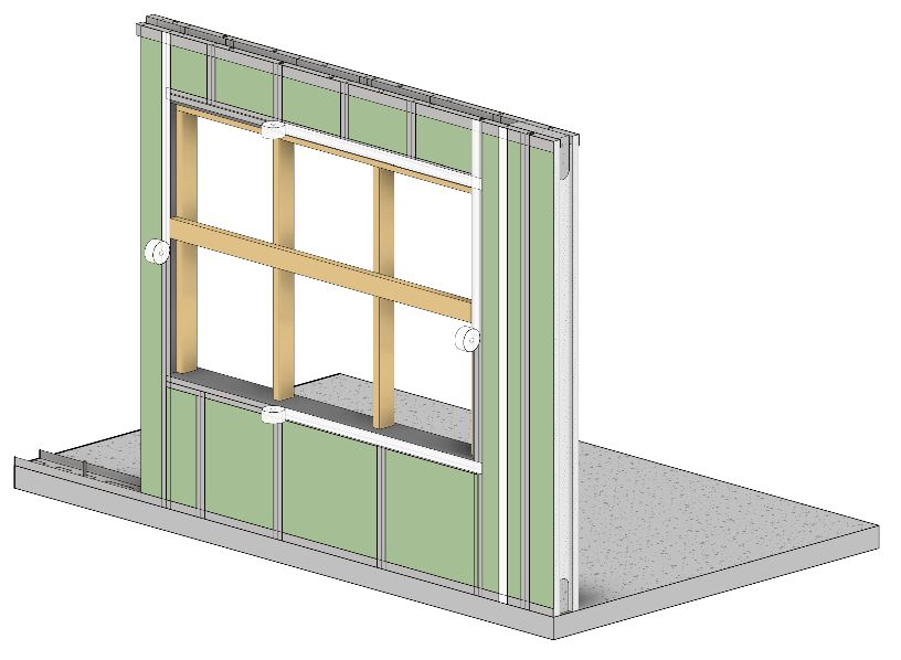
Table of Contents ...............................................................................................................Error! Bookmark not defined.
Overview ..................................................................................................................................................................... 3
   Parts Included........................................................................................................................................................................................ 3
   Tools and Supplies Required ................................................................................................................................................................. 3
Pre-Project Planning and Preparation........................................................................................................................... 4
   Foundation/ Footing Preparation: ........................................................................................................................................................ 4
   Bottom of Wall Dowel Installation: ....................................................................................................................................................... 4
   Hold Down Installation: ......................................................................................................................................................................... 4
Section 1: General Installation...................................................................................................................................... 5
   Step 1: Foundation Inspection & Preparation ....................................................................................................................................... 5
   Step 2: Mark Bottom Track Location ..................................................................................................................................................... 5
   Step 3: Install Bottom Track .................................................................................................................................................................. 5
   Step 4: Placing the First Panel ............................................................................................................................................................... 6
   Step 5: Level and Brace the First Panel ................................................................................................................................................. 6
   Step 6: Install Adjacent Panels .............................................................................................................................................................. 7
   Step 7: Install Top Cap ........................................................................................................................................................................... 7
   Step 8: Level and Brace the Wall ........................................................................................................................................................... 8
   Step 9: Keystone Panel (Final Panel) ..................................................................................................................................................... 9
   Step 10: Placing Rebar in Bond Beam ................................................................................................................................................. 10
Section 2: Openings and Specialty Panels ................................................................................................................... 11
   Window Panels.................................................................................................................................................................................... 11
   Door Panels ......................................................................................................................................................................................... 13
   Wide Openings .................................................................................................................................................................................... 13
   Standard Bracing for Wide Openings .................................................................................................................................................. 14
   Solid Shear Wall Panels ....................................................................................................................................................................... 15
   Final Inspection Checklist .................................................................................................................................................................... 15
Section 3: Concrete .................................................................................................................................................... 16
   Concrete Requirements ...................................................................................................................................................................... 16
   Tools and Supplies ............................................................................................................................................................................... 16
   Pre-Pour Checklist ............................................................................................................................................................................... 16
   Test the Concrete ................................................................................................................................................................................ 16
   Concrete Placement ............................................................................................................................................................................ 16
   Post-Placement ................................................................................................................................................................................... 18
   Repairs................................................................................................................................................................................................. 18
Section 4: Water Management System ....................................................................................................................... 18
   HercuWall’s Integral WRB ................................................................................................................................................................... 18
   Completing the Integral WRB .............................................................................................................................................................. 18
   Panel Joints ......................................................................................................................................................................................... 19
   Bottom Track ....................................................................................................................................................................................... 19
   Top Track ............................................................................................................................................................................................. 20
   Field Assembled Panels & Wide Openings .......................................................................................................................................... 20
   Penetrations in the WRB ..................................................................................................................................................................... 21
   Repairs to HercuWall WRB .................................................................................................................................................................. 21
   Beam Pockets/Beam Hangers ............................................................................................................................................................. 22
   Window Flashing ................................................................................................................................................................................. 22

                                                                                                                                                                                                            2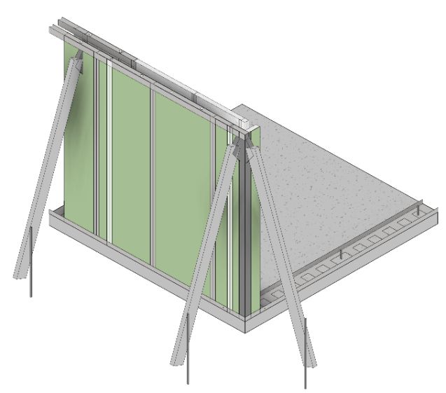
Overview
Congratulations on choosing HercuWall®! Please read and follow this installation guide in full. Contact HercuTech
support PRIOR to beginning the installation process should there be any questions. Contact us at 855-284-4037 and ask
for technical support or call your direct contact with any questions. Thank you for choosing HercuWall®.

           !      CAUTION
   ShearStrip® - warning - do not cut any ShearStrip® without written approval from the project Engineer of Record.
   ShearStrip® are critical to the structural integrity of the HercuWall® system. HercuTech Inc. is not liable for any
   structural issues arising from ShearStrip® being cut or altered on the job site. All warranties will be voided if
   ShearStrip® is determined to have been cut, manipulated, or otherwise altered in any way.

   Use caution when handling ShearStrip® and oversized panels to avoid cuts and injuries.

Parts Included                                                      •   Scaffold/Bracing
   •   Your Project Specific HercuWall® Kit                         •   Ladder(s)
          o HercuWall® Panels                                       •   Pneumatic Concrete Nail Gun or powder-
          o HercuWall® Top Track                                        actuated fastener (Optional)
          o HercuWall® Bottom Track                                 •   Ramset concrete nails
          o Sheathing Tape                                          •   Screw gun w/ #2 Phillips head driver bits
          o Installation Packet                                     •   Modified Truss Phillips Head Screws - #8x3/4”,
                                                                        self-drilling, Zinc plated
                                                                    •   Rebar, as specified
Tools and Supplies Required                                         •   Ready-Mix Concrete per HercuWall Mix
                                                                        Specification
   •   Safety glasses
                                                                    •   Concrete pump
   •   Gloves
                                                                    •   Concrete pencil vibrator
   •   Tape Measure
                                                                    •   Steel trowel for concrete finishing
   •   4-foot Level
                                                                    •   Rebar Tie Wire
   •   Caulk gun
                                                                    •   Tie Wire Twister
   •   Utility Knife
                                                                    •   Chalk Line
   •   Elastomeric Sealant (meets or exceeds ASTM C
                                                                    •   Straight-Cut Aviation Snips
       920: Type S, Grade NS, Class 25)
                                                                    •   Rafter Square or Speed Square

                                                                                                                         3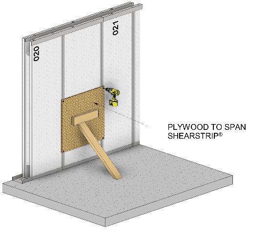
Pre-Project Planning and Preparation
Foundation/ Footing Preparation:
   Review the HercuWall® Installation Packet prior to placement of concrete in the footings and/or slab. The drawings
   in the Installation Packet will identify all rebar requirements as well as locations and sizing needed for installation
   from the footings/slab to the wall panels.

   Validate all dimensions listed in the HercuWall® Installation Packet with the formwork and rebar locations prior to
   placement of concrete in the footings/slab.

Bottom of Wall Dowel Installation:
   Refer to the HercuWall® Installation Packet for bottom of wall dowel requirements.

       •   J-Bolts and/or rebar dowels may be used for this step. Please verify the spacing, sizing and projection
           requirements for the dowels in your HercuWall® Installation Packet.
       •   Bottom of wall dowels are to be installed prior to, or during, the placement of the concrete slab. If locations
           are missed, please contact your Engineer of Record and your HercuTech Inc. Project Manager for an epoxy
           embedded dowel detail.

Hold Down Installation:
   Continuous rebar projecting from the footing/slab into shear wall panels must be installed per the approved
   construction documents. This information is also available in the HercuWall® Installation Packet for the designed
   HercuWall® Kit.

                                                                                                                         4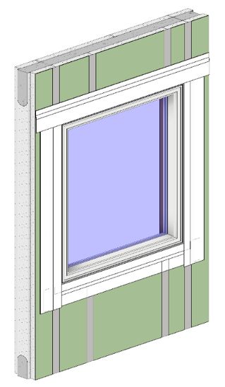
Section 1: General Installation                                   To mark the track locations:
                                                                      1.    Snap chalk lines around the perimeter of the
Step 1: Foundation Inspection &
                                                                            foundation. These chalk lines will represent the
Preparation                                                                 interior edge of the HercuWall® bottom track.
The foundation will have vertical dowels or rebar studs,              2.    The chalk lines must match the panel layout in the
projecting three inches above the slab surface, along the                   Installation Packet to ensure proper fit of all wall
perimeter of the house where HercuWall® panels will be                      panels.
installed.                                                            3.    Verify all door opening locations and mark where the
                                                                            opening will be to show that no bottom track will be
                                                                            needed in that section of the wall.

                                                                  Step 3: Install Bottom Track
                                                                  Bottom track is used to locate HercuWall® panels during
                                                                  installation and to prevent movement of the panels during
                                                                  concrete placement. The track is continuous wherever
                                                                  HercuWall® panels contact the slab, with the only exception
                                                                  being door openings.

To inspect and prepare the foundation:                            To install the bottom track:
    1.   Measure the slab for accuracy.
    2.   Clean dirt and obscurities from the perimeter of the          1.    It is recommended to start at a corner.
         slab where HercuWall® will be installed.                      2.    When positioning the first length of track, place the
    3.   Be sure dowels or rebar studs are not protruding                    track with the interior edge against the chalk line.
         into door way openings.                                             Place the track so that the punched holes in the
    4.   Rebar must be +/- 1 inch from the centerline of                     bottom of the track align with majority of dowels.
         HercuWall®.                                                         Trim the bottom of the track with snips to avoid the
    5.   Measure to ensure that dowel spacing is not greater                 remaining dowels.
         than specified by the engineer.                               3.    Mark and miter cut the end of the track to 45
    6.   Repair any deviations in the slab, greater than ¼ inch              degrees, at the slab corner, with the long side being
         in 10 feet, per industry standards.                                 the exterior side. The exterior side of the track is
    7.   If dowels or rebar studs are missing contact your                   easily identified by the weep holes located along
         Engineer of Record (EOR) for an engineered solution.                the exterior bottom edge. Corners are miter cut to
                                                                             prevent overlapping of the track.
Step 2: Mark Bottom Track Location                                     4.    Apply a continuous ¼” bead of elastomeric sealant
Chalk lines are used to mark the locations where bottom                      approximately 1” to the outside of chalk line on the
track will be installed. The placement of these lines is                     slab where the track will be installed. This will form
documented in the Installation Packet provided with your                     an air and moisture barrier between the foundation
HercuWall® Kit.                                                              and the track. NOTE: It is recommended to install
                                                                             sealant continuously to edge of slab and at all
                                                                             seams where adjoining track has a butt joint both
                                                                             on the horizontal joint as well as the vertical.

                                                                      Continued

                                                                                                                                 5
Step 3: Install Bottom Track (Continued) Step 4: Placing the First Panel
HercuWall® panels are sequentially numbered, starting with
001. The first panel is typically a corner panel. The panel
number will be located on the top left interior side of the
HercuWall® panel.
5. Place the track on the slab with the inside edge on
the chalk line and the mitered cut aligned with the
corner of the slab.
6. Attach, or pin, the track to the foundation using a
powder- actuated or pneumatic fastener. Fasteners
are recommended to be placed at the midline of
the track and are spaced approximately 24 inches
apart. For short sections of track, at least two
fastening points are required. Pinning the track to
the slab is only necessary to prevent the bottom
track from moving during installation of panels and
concrete.
To install the first panel:
1. Place the corner panel into the bottom track making
sure it is fully inserted in the track.
2. Use a level to hold the panel roughly plumb in both
directions.
3. Install a #8 x 3/4” Modified Truss Head Self-Drilling
Screw through the bottom track into each side of the
outside metal corner nailer.
7. Install additional lengths of track in the same
manner making sure all corners are miter cut.
8. When a door opening is reached, cut the track so
that it does not obstruct the opening.
**NOTES**
• HercuWall® bottom track is non-structural, so it may
Step 5: Level and Brace the First Panel
be altered to allow clearance for dowels or pipes
Once the corner is fastened, it is necessary to level and brace
protruding out of the slab.
this panel. This step is crucial for maintaining straight and
level walls.
6To brace the first panel:
1. Attach braces to the corner nailer on the exterior of
the building, one facing each direction.
2. Once the panel is plumb, secure the braces.
**NOTE**
Bracing may be installed on either the interior or
exterior side of the wall system. When bracing is
installed on interior side of the wall, plumb and level
panels 1 and 2 as an assembly
To install adjacent panels:
1. Set the panel into the track adjacent to the
previous panel.
2. Slide the panel over to engage with the previously
installed panel.
3. Ensure that the tongue and groove is fully engaged.
4. Insert a screw through the bottom track into each
ShearStrip® to hold the panel in place.
5. Periodically check that the panels are sitting level in
the track by placing a level, vertically, on the
Step 6: Install Adjacent Panels narrow end of the panel.
The second panel, numbered 002, is placed adjacent to the 6. Repeat this step until you have 12 linear feet of
corner panel (001). The panels interlock by means of a tongue wall.
and groove for ease of installation.
**NOTE**
The second and third panel, numbered 002 and 003, are
placed adjacent to the corner panel (001). The panels • For non-standard panels such as windows, doors or
interlock with the left and right sides of the corner panel by shear walls, see Section 2 Openings and Specialty
means of a tongue and groove for ease of installation Panels for specific installation instructions.
Step 7: Install Top Cap
Once 12 linear feet of HercuWall® has been installed, it is
recommended that you “fall back” and start the installation
of the top cap. There are two parallel top caps to install at the
top of the HercuWall® Panels. Top caps tie the panels
together and provide additional rigidity to the wall assembly.
7To Install the top cap:
1. Begin installation of the top cap at the corner,
starting on the side of the wall that bracing is being
installed.
2. Corners may be miter cut, or the obstructing legs
notched for proper fit. Do not overlap/stack the top
cap.
3. The top cap has punched holes on the top surface
that are offset from center. It is important to
properly place the top caps with the holes offset
toward the center of the wall. These holes provide
locations for wires and pipes to exit through the top
of the wall panel.
4. Ensure that the tongue and groove joint between
panels are tight
5. Install a #8 x 3/4” Modified Truss Head Self-Drilling
Screw through the Top Track into each ShearStrip®. Step 8: Level and Brace the Wall
6. It is recommended that the interior and exterior Once the first section of top cap has been installed, the wall
joints of the top caps are staggered as much as must be leveled and braced. It is recommended that bracing
possible to keep the wall straight and rigid until the be installed at 6 to 8 foot increments, or when additional
concrete is poured. bracing is specifically called out in the Installation Packet.
To level and brace the wall:
1. Place a level on the ShearStrip® that you are attaching
the brace to.
2. Move the panel until it is level, then attach the brace to
the interior or exterior of the slab.
3. Continue alternately placing panels and top caps,
stopping to level and brace the walls periodically.
**NOTES**
• It is best to install all the braces on the same side of
the HercuWall® system whenever possible. Because
the panels are solid you do not need to brace both
sides.
• Some panels may have special bracing/over forming
requirements. Check Installation Packet for specific
7. Once the first top cap is installed, cut a second top instructions on any specialty panels.
cap to a length and fasten it to the opposite top • When using wood bracing, install a few additional
edge of the panel. Move down to the second braces on the opposite side of the panel for
shearstrip® from the corner and attach to the additional support.
proceeding flange of the shearstrip®. • When utilizing an integral scaffold/bracing system,
**NOTES** ensure that it is installed in accordance with the
manufacturer’s recommendations.
• It is best to install top cap with an aide like a • Depending on site, soil, and weather conditions
stringline or laser to ensure a consistent top of wall additional braces may be needed to ensure the walls
elevation stays straight while pouring concrete.
86. Press the panel down into place until it is level with
the plate height of the adjacent panels.
7. Lift the interior corner trim above the corner and make sure
the trim is engaged with the cut outs in panels 002 and 099,
then slide down to meet bottom track.
Step 9: Keystone Panel (Final Panel)
The keystone panel is the last panel to be installed and is
typically narrower than a standard panel. Installation of the
keystone panel is a slightly different from installing previous
panels.
To install the keystone panel:
1. The keystone (final) panel cannot be slid into place.
2. Measure the width of the keystone panel and the
opening where it will be installed to verify a proper
fit.
3. If the opening for the panel is too narrow, make
sure all adjacent panels are properly engaged and
tightly pushed together to gain the necessary
width.
4. Lift the keystone panel above the top plate height. 8. Fasten, brace and apply top cap to the keystone
5. Make sure the tongue and groove are properly panel in the same manner as all the other panels.
engaged and then slide it down into place.
94. Most windows and doors will require additional
rebar in the header above the opening. This
additional rebar will be installed at the factory and
will arrive at the jobsite with no additional
installation needed.
*NOTE*
• Some panels, such as Solid Shear Panels, may
require the addition of vertical rebar. Vertical
rebar should be installed prior to the horizontal
bond beam rebar. See Installation Packet for
details.
Step 10: Placing Rebar in Bond Beam
HercuWall® utilizes integral ShearStrip® technology to
vertically reinforce the concrete columns. No additional
vertical rebar is required for standard panel installation. A
single horizontal rebar, however, must be installed around
the perimeter of the wall within the bond beam at the top of
the wall.
To install the bond beam rebar:
1. Place the rebar into the factory pre-installed rebar
hooks located in the bond beam. Typically, a single
#4 rebar is used for standard wall panels (spacing,
quantity and size may vary per plan).
2. Overlap rebar per industry standard practices.
3. It is not necessary to tie the rebar to the hooks, but
is recommended to tie spliced rebar together to
avoid displacement during concrete placement.
10Section 2: Openings and Specialty
Panels
Window Panels
Each HercuWall® kit includes window panels with factory
installed casements dimensioned to the determined rough
openings to reduce installation time and minimize jobsite
waste. The rough openings are cased with a galvanized 20
gauge metal casement. It is important to temporarily brace
3. Ensure that the tongue and groove is fully engaged.
the rough openings during the concrete placement to ensure
4. Insert a screw through the bottom track into each
that the opening remains true.
ShearStrip® to hold the panel in place.
There are two types of window panels: 5. Install top cap as outlined in Section 1, Step 7
6. Brace the panel as outlined in Section1, Step 8
Factory Assembled 7. Install temporary bracing to keep the rough
opening true during concrete placement
• Factory assembled window panels are one-piece
panels, fully assembled at HercuTech and are
installed in the same manner as a standard panel.
Factory assembled window panels are limited to four
feet in width.
Field Assembled
• Field assembled window panels are typically shipped
in four pieces; a header, a sill and two jamb sections.
Field assembled window panels are utilized for larger
openings where the rough opening width is over
3’0”.
To install field assembled window panels:
To install factory assembled window panels:
1. Set the first jamb section into the track adjacent to
1. Set the panel into the track adjacent to the
the previous panel.
previous panel.
2. Slide the panel over to engage with the previously 2. Slide the jamb over to engage with the previously
installed panel.
installed panel.
113. Ensure that the tongue and groove is fully engaged.
4. Set the sill section into the track, adjacent to the first
jamb section.
5. There is no tongue and groove between the jamb
and sill. Slide the sill over so that the sill casement 11. Ensure that all window casing joints fit properly and
tab is against the jamb casement. the opening is square.
6. Lift the jamb section slightly to allow the sill 12. Insert a screw at every interior and exterior
casement tab to move behind the jamb casement. intersection of horizontal and vertical ShearStrip®.
Slide the jamb back down to fully engage bottom 13. Insert 2 – screws; spaced 2” from centerline of the
track. casement and ¾” from the intersecting sill or header
7. Insert a screw through the bottom track into each casement, into each jamb casement intersection per
ShearStrip® to hold the jamb and sill in place. the below diagram.
8. Set the second jamb directly into the bottom track
so that sill casement tab is behind the jamb
casement.
9. Insert a screw through the bottom track into each
ShearStrip® to hold the jamb in place. 14. Install top cap as outlined in Section 1, Step 7
10. Set the header section between the top of the two 15. Brace the panel as outlined in Section 1, Step 8.
jamb sections lowering the header until the header 16. Install temporary bracing to keep the rough opening
casement tabs are fully engaged behind the left and true during concrete placement
right jamb casements.
126. Bottom track should end no more than two inches
from the opening.
7. Measure the opening at the top and adjust the
bottom to match.
8. Check the opening with a square.
9. Insert a screw through the bottom track into each
ShearStrip® to hold the panel in place.
10. Install top cap as outlined in Section 1, Step 7.
11. Brace the panel as outlined in Section 1, Step 8.
12. Install temporary bracing to keep the rough
opening true during concrete placement
17. Brace the panel as outlined in Section 1, Step 8
**NOTES**
• HercuTech may include window blanks for some
openings. Window blanks are EPS inserts that are
used in lieu of bracing an opening
Door Panels
Each HercuWall® kit includes door panels with factory
installed casements dimensioned to the determined rough
openings to reduce installation time and minimize jobsite
waste. The rough openings are cased with a galvanized 20
gauge metal casement. It is important to temporarily brace
the rough openings during the concrete placement to ensure
that the opening remains true **NOTES**
To install door panels: • Some door panels may have special bracing/over
1. Remove the temporary spacer at the base of the forming requirements. Check Installation Packet for
door. specific instructions on any door panels.
2. Set the door panel into the track adjacent to the
Wide Openings
previous panel.
3. Slide the panel over to engage with the previously (Overhead Doors, Arcadia Doors, Etc.)
installed panel. Panels with wide openings may be included in the
HercuWall® kit. These panels are most commonly used when
the installation of a large door such as an overhead garage
door or arcadia door is required. Due to their size, these
panels are typically delivered in multiple pieces and are
assembled at the jobsite.
Wide openings typically require more reinforcement and
have more concrete in the adjacent cells for added strength.
Wide opening panels may be delivered with either multiple
EPS blanks that fit together to keep the opening square
during concrete placement, or instructions for properly
bracing the opening. Refer to HercuWall® kit Installation
4. Ensure that the tongue and groove is fully engaged. Packet for EPS blank configuration or bracing requirements.
5. If necessary, trim any bottom track that extends
into the door opening.
13To install wide opening panels: 12. Brace the panel as outlined in Section 1, Step 8.
1. Set the first jamb section into the track adjacent to 13. Install additional rebar as required and outlined in
the previous panel. the Installation Packet.
2. Insert the jamb into the track while engaging the 14. Re-install the EPS Inserts into the door opening or
tongue and groove of the previously installed panel. brace per instructions in the Installation Packet.
**NOTES**
• Some door panels may have special bracing/over
forming requirements. Check Installation Packet for
specific instructions on wide opening panels.
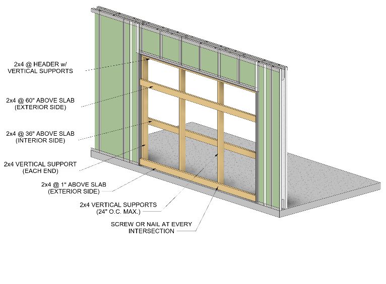
Standard Bracing for Wide Openings
For wide openings that were delivered without accompanying
3. Ensure that the tongue and groove is fully engaged.
foam blanks or precise instruction in the Installation Packet,
4. Insert a screw through the bottom track into each
use the following standard method for bracing.
ShearStrip® to hold the jamb in place.
5. Set the second jamb section into the track at the To install wide opening bracing:
proper distance from the first jamb. This distance is 1. Refer to the diagram at the end of this section for
the rough opening. details.
2. Install horizontal 2 x 4’s against the header. These
must span the entire length of the opening.
3. Install vertical 2 x 4’s against the two jambs. These
will support the header 2 x 4(s).
4. Install additional vertical 2 x4’s to support the
header. These should be spaced at a maximum of
24” on center and at joints in the header 2 x 4
bracing.
6. Set the header section between the top of the two
5. Install additional horizontal 2 x 4 supports between
jamb sections, lowering the header until the header
the two jambs. Screw or nail these supports to all
casement tabs are fully engaged behind the left and
vertical supports. Placement of these supports
right jamb casements.
should alternate between interior and exterior sides
of the vertical supports.
6. Install top cap as outlined in Section 1, Step 7.
7. Brace the panel as outlined in Section 1, Step 8.
7. Ensure that all casing joints fit properly.
8. Measure the opening at the top and move the
bottom to match.
9. Check the opening corners with a square and the
sides of the opening with a level
10. Insert a screw through the bottom track into each
ShearStrip® to hold the second jamb in place.
11. Install top cap as outlined in Section 1, Step 7.
14• See Installation Packet for details on bracing/over
forming requirements.
Solid Shear Wall Panels • Shear wall panels should be filled with concrete in 2
HercuWall® utilizes a solid core shear panel when required. to 3 passes to ensure proper filling and to minimize
These panels are factory assembled and require no additional concrete form pressure.
jobsite assembly. Shear wall panels include pre-installed
horizontal supports to accommodate the increased concrete
pressure in these areas.
Installation Inspection
To Install a shear wall panel:
1. Review and confirm that rebar projecting out of the Final Inspection Checklist
slab is in the correct position and aligns with the Once all panels have been installed, it is imperative to
shear wall panel. perform a final inspection of the entire HercuWall® panel
2. Lift the panel over rebar dowels and place it into the installation. Making changes to the walls during or after
track. Shear wall panels cannot be slid into position concrete placement is very difficult. Inspecting and verifying
the items in the following checklist prior to receiving concrete
will help to ensure trouble-free concrete placement.
1. Inspect all bracing.
2. Check that all walls are straight and level.
3. Check that all panels are properly attached to the
bottom track and top cap with screws.
4. Verify rebar is in place and meets lap requirements.
5. Check that all recommended additional bracing is in
place and secure per HercuWall® Installation Packet.
6. Verify that scaffolding is installed per manufacturers
recommendations.
7. Inspect all panels for any damage that may have
occurred during installation that might affect
3. Verify that both the exterior and interior side of the concrete placement.
panel are fully engaged in the bottom track. 8. Mark the installation locations of all embeds, truss
4. Ensure that the tongue and groove is fully engaged. ties, and j-bolts.
9. Verify that all EPS window and door blanks are
installed to ensure openings stay square during
pouring.
10. Verify Jurisdiction Inspection has been completed
and approved.
5. Insert a screw through the bottom track into each
ShearStrip® to hold the panel in place.
6. Install top cap as outlined in Section 1, Step 7.
7. Brace the panel as outlined in Section 1, Step 8.
**NOTES**
1516. Verify that the concrete pump has the proper size
Section 3: Concrete and length of hose to easily reach all areas of the
installation
17. Schedule the concrete pump to arrive 30 minutes
prior to concrete delivery time
! Important 18. Discuss pump speed and review hand signals with
the pump operator
Concrete Requirements
A specified concrete mix design is required for all
HercuWall® installations. If concrete is out of tolerance from
Test the Concrete
specifications and/or acceptance conditions, do not When concrete arrives at the job site, it is important to check
continue with the pour. Please refer to the Approved the slump, or flowability, of the concrete. The concrete mix
Construction Documents and the HercuWall® Installation design for HercuWall® is extremely flowable, therefore, a
Packet for concrete specifications and acceptance standard slump test cannot be used to test the mix. The
conditions. proper method to test HercuWall® concrete is by means of a
slump flow test per ASTM C1611 typically used for self-
consolidating concrete instead of the traditional slump test
used for stiffer concrete. This test uses an inverted slump test
Tools and Supplies
cone and a large base plate to measure the concrete spread
Having proper tools and supplies on the job site when
which is typically between 20 and 24 inches in diameter.
concrete is delivered is important to the overall success of
the project. The following items must be available and ready **NOTE**
for use when concrete arrives. • Most ready-mix companies will hold back a small
amount of water from the mix they deliver. Ask the
• Concrete Pumping/Delivery System
delivery driver how much water was held back. This
o Grout Pump
amount of water may be used to adjust the slump
§ 2” Hose
flow of the concrete if necessary.
o Overhead Boom Pump
• Do not add more water than what was held back by
§ 4” Flexible Hose
the ready-mix company.
• Concrete mix specification
• If the slump flow slightly exceeds 24 inches in
• Certified ACI Concrete Testing Service to verify
diameter, allow the mix to spin in the truck for an
acceptance conditions
additional 10 minutes and re-test. This will help
• External form vibrator and/or pencil vibrator
reduce the slump flow of the concrete.
• Concrete finishing tools
• Proper PPE for Safety
Concrete Placement
Pre-Pour Checklist Once the concrete mix has been tested and determined to be
On the day of concrete placement, a little planning goes a within specification, it is time to place the concrete in the
long way. The following items can be completed prior to HercuWall® panels.
concrete delivery to help ensure a successful pour.
HercuWall® panels are filled with concrete in two lifts, or
11. Adequate PPE usage
passes. The first pass will fill the base beam, vertical columns
12. Scaffolding/ladders meet manufacturers
and the lower half of solid shear wall panels. The second pass
requirements
will fill the bond beam and the remaining unfilled shear wall
13. Approved pump priming, testing and washdown
sections.
area are setup
14. Ensure all embeds are accessible
15. Select areas for positioning the concrete truck and
pump that have ample access, stable ground, no
overhead/underground utilities and are within
planned pumping distance
16Placing the concrete can be divided into four steps: When filling window jambs use an external form vibrator
sparingly on one of the sill ShearStrip® to improve
• Pump Priming/Preparation concrete flow under the window opening.
• First Pass Concrete Placement
**NOTE**
• Second Pass Concrete Placement
• As you place concrete ensure that the vertical
• Finishing & Embedment Placement
columns are filled without bridging.
Step 1: Pump Priming/Preparation
Step 3: Second Pass Concrete Placement
It is the responsibility of the pump operator to prime the
Start at the same corner as the first pass
concrete pump and hoses with concrete prior to
placement. It is extremely important that all the slurry in Use a low pump speed to fill the bond beam
the hose and pump hopper is completely purged prior to
placing concrete in the wall. Point the hose output down at an angle rather than
straight down. This will promote better flow
Step 2: First Pass Concrete Placement characteristics while integrating concrete with the
Concrete placement typically starts in the corner and HercuWall® system.
continues around the structure.
Fill the bond beam while moving steadily around the
Start at a low pump speed and slowly increase to match perimeter
placement capability. Do not try to pump faster than the
natural flow of the concrete.
Point the hose output down at an angle rather than
straight down into the columns. This will promote better
flow characteristics while integrating concrete with the
HercuWall® system.
Fill 4 or 5 columns at a time, alternating between them
until concrete is almost to the bond beam, then move to
the next 4 or 5.
Fill shear wall sections completely
Only when necessary, vibrate to ensure complete concrete
consolidation
It is recommended to have a second person follow behind
with a trowel to level the concrete with the top of the wall
and to redirect excess concrete to low spots.
Step 4: Finishing & Embedment Placement
Finish the top surface of the bond beam concrete using a flat
Fill shear wall sections approximately half way in the first trowel. The upper surface of the top cap is used as a screed
pass. edge to maintain the proper level Continued
17ShearStrip® bridging the damaged section of EPS
Install all embeds, J-bolts and truss ties per the Approved inserting screws through the gusset into the
Construction Documents, Manufacturer’s Recommendations ShearStrip®
and/or standard practices. 3. Brace the gusset per the below diagram
**NOTE**
19. This step can be started while Step 3 is in process.
Post-Placement
Best Practice is to remove scaffolding and bracing per system
manufacturers instructions. Remove over forming/bracing
from the forms. Remove window blanks, if provided, and
large opening bracing.
**NOTE**
Contact your HercuTech Inc Project Manager for recycling
coordination of any EPS opening blanks, if provided.
Repairs Section 4: Water Management
HercuWall Panels are repairable in the field as long as there is System
no damage to the ShearStrip®. If there is a damaged
ShearStrip® please stop immediately and call your HercuTech HercuWall’s Integral WRB
representative for replacement instructions.
HercuWall® Series 8, Type S panels comes with an
integral Film Laminate that serves as a WRB (water
The EPS functions as both concrete formwork (before resistive barrier) when the below steps are completed.
concrete placement) and rigid insulation (after concrete The HercuWall WRB meets or exceeds IRC and IBC code
placement). If the EPS is damaged, you may provide a simple requirements for a WRB.
repair using over forming methodology.
It is important to maintain the continuity of the integral
HercuWall® Film Laminate to maintain a true functioning
WRB from top to bottom of HercuWall. This section will
provide guidance for completing the WRB system at
panel joints and in instances of flanged and un-flanged
penetrations, damaged laminate and where beams are
needed to penetrate the surface of the WRB film
laminate.
Completing the Integral WRB
Once the HercuWall® System is installed it is required to
complete the WRB System by applying the two-inch-wide
sheathing tape included in the HercuWall® kit to the
To repair damaged EPS prior or during the concrete HercuWall® panel joints, top track (when no other code
placement: approved flashing methods are utilized), bottom track
1. Remove the damaged EPS and clear out any debris (when no other code approved flashing methods are
that may interfere with concrete placement utilized), large opening assemblies and to repair damages
2. Install a plywood gusset from ShearStrip® to to the laminate. This must be completed prior to
concrete placement. Do not substitute HercuWall®
18sheathing tape with any other product. Sheathing tape Bottom Track
should only be applied in dry conditions at temperatures To complete the continuity of the WRB, it is required to
between 0°F and 122°F. install the sheathing tape at the bottom track of
HercuWall unless an alternative, code approved flashing
Panel Joints methodology is used:
To install sheathing tape on panel joints:
1. Ensure that the surface of the HercuWall WRB is 1. Ensure that the surface of the HercuWall WRB
clean, dry and free of debris and Bottom Track are clean, dry and free of
2. Apply the sheathing tape on the WRB with the debris
tape centered on the panel joint starting at the 2. Apply the sheathing tape on both surfaces with
top of the wall the tape centered on the joint of the Bottom
3. Apply tape so that it lays flat continuously on Track and WRB
the surface of the HercuWall WRB from top of 3. Apply tape so that it lays flat on both the surface
wall to bottom of wall of the HercuWall WRB and the Top Track
4. Press tape to the surface of the HercuWall WRB 4. Press tape to the surface of the HercuWall WRB
using a J-roller or stiff bristle scrub brush to and Bottom Track using a J-roller or stiff bristle
ensure a proper bond scrub brush to ensure a proper bond
5. Repeat until all panel joints have sheathing tape 5. Repeat until the sheathing tape is applied
applied continuously around the bottom perimeter of the
wall
**NOTE**
**NOTE**
When lap splicing the sheathing tape, overlap the tape
ends a minimum of 2 inches When lap splicing the sheathing tape, overlap the tape
ends a minimum of 2 inches
19Top Track Field Assembled Panels & Wide Openings
To complete the continuity of the WRB, it is required to In Section 2 of the HercuWall Installation Guide we
install the sheathing tape at the top track of HercuWall discussed how to assemble the Field Assembled Window
unless an alternative, code approved flashing Panels and Wide Openings. It is important to install the
methodology is used: sheathing tape to the Header and Sill prior to installing
the sheathing tape on the Jambs. To complete the
1. Ensure that the surface of the HercuWall WRB continuity of the HercuWall WRB at these conditions:
and Top Track are clean, dry and free of debris
1. Starting at the Header condition ensure that the
surface of the HercuWall WRB, integral Window
2. Apply the sheathing tape on both surfaces with Casement and ShearStrip are clean, dry and free
the tape centered on the joint of the Top Track of debris
and WRB
3. Apply tape so that it lays flat on both the surface 2. Apply the sheathing tape on all surfaces with
of the HercuWall WRB and the Top Track the tape centered on the application area
4. Press tape to the surface of the HercuWall WRB 3. Apply tape so that it lays flat on all surface of
and Top Track using a J-roller or stiff bristle the HercuWall WRB, integral Window Casement
scrub brush to ensure a proper bond and ShearStrip
5. Repeat until the sheathing tape is applied 4. Press tape to the surface of the HercuWall WRB,
continuously around the top perimeter of the integral Window Casements and ShearStrip
wall using a J-roller or stiff bristle scrub brush to
ensure a proper bond
**NOTE** 5. Repeat the previous steps for the Sill (on Field
Assembled Window Panels only) and both
When lap splicing the sheathing tape, overlap the tape
Jambs
ends a minimum of 2 inches
**NOTE**
When lap splicing the sheathing tape, overlap the tape
ends a minimum of 2 inches
20Penetrations in the WRB
Penetrations in the HercuWall WRB can occur for a
variety of reasons from intersecting structural members
to utility piping and raceways. It is important to
integrate additional flashing systems to complete the
continuity of the WRB when penetrating the HercuWall
WRB. Select a code approved flashing method that is
appropriate for the penetration type.
Please review the below section to understand some of
the many different conditions where penetrating the
HercuWall WRB may occur.
Non-Flanged Penetrations
When treating a non-flanged penetration to provide
continuity to the HercuWall WRB, apply the desired
flashing system per the manufacturer’s specifications and
required building code to ensure proper integration of
this system with the HercuWall WRB.
Repairs to HercuWall WRB
If there are any tears, punctures or damage to the
HercuWall® WRB, a repair can be accomplished with the
sheathing tape supplied with your HercuWall System
Flanged Penetrations
When treating a flanged penetration or when joining a
rigid flashing system to the HercuWall WRB it is
important to provide continuity to the HercuWall WRB.
Apply the desired flashing system per the manufacturer’s
specifications and required building code to ensure Install the sheathing tape over the area in need of repair
proper integration of this system with the HercuWall using a shingling methodology, installing the sheathing
WRB. tape from the bottom up. Ensure that there is a
minimum of 1” of sheathing tape bonded to the
HercuWall WRB around the entire perimeter of the
damaged WRB.
21Beam Pockets/Beam Hangers
The HercuWall® system can be modified in cases where Placement of HUC Hanger (Example Only)
intersecting beams are required to pass through, bear on
or hang off the concrete structure. Apply the desired 3. Wrap structural member with approved flashing
flashing system per the manufacturer’s specifications and tape/system.
required building code to ensure proper integration of
this system with the HercuWall WRB.
1. Remove portion of EPS from the panel where
indicated.
a. Start by cutting away the flange of the top
track to allow access to the top portion of
EPS.
b. Cut the required area of EPS out of the Window Flashing
panel. Lines designated are for general
The HercuWall® System and its opening casements can
guides and not meant to supersede
be utilized for any window system. Shown in the
structural elements’
following figure is a casement window with fins. Apply
specifications/dimensions.
the desired flashing system per the manufacturer’s
specifications consistent with standard construction
methods and required building code to ensure proper
integration of this system with the HercuWall WRB.
2. Install the required structural anchor/hanger.
a. After removal of EPS section, install the
anchor/hanger element per the
manufacture’s specifications.
b. Install the structural member (wood beam
shown for example only).
22You can also read