UltraFLEX HD Test System Power-One 40KVA Power Vault Service Manual - Product Number: 1-155462 Rev.: AC
←
→
Page content transcription
If your browser does not render page correctly, please read the page content below
UltraFLEX HD Test System
     Power-One 40KVA
Power Vault Service Manual

   Product Number: 1-155462 Rev.: AC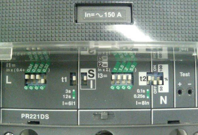
Limited Production Rights
This document may be reproduced by a Teradyne customer solely
for internal use by the customer's employees whose responsibilities
include Teradyne equipment. Any copy of this document, or portions
thereof, must contain the copyright and proprietary rights notice as
stated on the original document.
The material in this document is subject to change without notice.
Teradyne's liability for any errors in this document is limited to the
correction of errors. Teradyne WILL NOT BE RESPONSIBLE IN
ANY EVENT FOR ERRORS IN THIS DOCUMENT OR FOR ANY
DAMAGES, INCIDENTAL OR CONSEQUENTIAL (INCLUDING
MONETARY LOSSES), that might arise from the use of this
document or the information in it.
Restricted Rights Legend
Use, duplication or disclosure by the Government is subject to
restrictions set forth in subdivision (b) (3) (ii) of the Rights in
Technical Data and Computer Software clause of DFARS
52.227-7013.
Credits and Trademarks
TERADYNE logo is a registered trademark of Teradyne, Inc.
Other product names mentioned in this document may be
trademarks of their respective companies and they are mentioned
here for identification purposes only.
Copyright ©Teradyne, Inc. 2008
Printed in the U.S.A.
Print History

Manual Name:UltraFLEX HD Test System Power-One 40KVA Power Vault Service
Manual

Part Number: 1-155462

Revision Level: AC

Reason for Change

                             Table 1: Revision History

     Rev                                 Change

    AB     Initial Release
    AC     Changed 36 KVA to 40KVA, added Teradyne part numbers to spares list
           table, added Teradyne part number for power vault to Chapter 1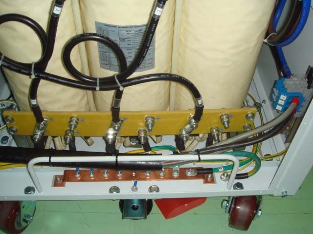
Contents

           1 About This Manual . . . . . . . . . . . . . . . . . . . . . . . . . . . . . . . . . . . . . . . . . . . . . . . . . 2-1
               1.1 Viewing This Manual Online . . . . . . . . . . . . . . . . . . . . . . . . . . . . . . . . . . . . . 2-1
           2 . . . . . . . . . . . . . . . . . . . . . . . . . . . . . . . . . . . . . . . . . . . . . . . . . . . . . . .Introduction2-2
           3 . . . . . . . . . . . . . . . . . . . . . . . . . . . . . . . . . . . . . . . . . . . . . . Power Vault Overview2-3
           4 Unpacking . . . . . . . . . . . . . . . . . . . . . . . . . . . . . . . . . . . . . . . . . . . . . . . . . . . . . . . 2-5
           5 . . . . . . . . . . . . . . . . . . . . . . . . . . . . . . . . . . . . . . . . . . . Preparing the Power Vault2-6
           6 . . . . . . . . . . . . . . . . . . . . . . . . . . . . . . . . . . .Adding Input Cable and Tester Cable2-8
               6.1 Connect the input cable into power vault . . . . . . . . . . . . . . . . . . . . . . . . . . . 2-8
               6.2 Connect the tester cable into power vault . . . . . . . . . . . . . . . . . . . . . . . . . . . 2-9
           7 . . . . . . . . . . . . . . . . . . . . . . . . . . . . . . . . . . . . . . . . . . Input Voltage Changeover2-11
               7.1 . . . . . . . . . . . . . . . . . . . . . . . . . . . . . . . . . . . . . . Rewiring the Transformer2-11
               7.2 Reconfiguring the Main Circuit Breaker-CB1 . . . . . . . . . . . . . . . . . . . . . . . 2-15
           8 . . . . . . . . . . . . . . . . . . . . . . . . . . . . . . . . . . . . . . . . . . . . . . . . . . Testing the Vault2-17
           9 . . . . . . . . . . . . . . . . . . . . . . . . . . . . . . . . . . . . . . . . . . . . . . . . . .Closing the Vault2-18
           10 . . . . . . . . . . . . . . . . . . . . . . . . . . . . . . . . . . . . . . . . . . . . . . .Schematic Drawing2-19
           11 Product specifications . . . . . . . . . . . . . . . . . . . . . . . . . . . . . . . . . . . . . . . . . . . . 2-21
               11.1 . . . . . . . . . . . . . . . . . . . . . . . . . . . . . . . . . . . . . . . .Electrical characteristic2-21
               11.2 . . . . . . . . . . . . . . . . . . . . . . . . . . . . . . . . . . . . . . Mechanical Specification2-25
               11.3 . . . . . . . . . . . . . . . . . . . . . . . . . . . . . . . . . . . . . . . . . Agency Certifications2-31
               11.4 Environmental Conditions . . . . . . . . . . . . . . . . . . . . . . . . . . . . . . . . . . . . . 2-31
           12 . . . . . . . . . . . . . . . . . . . . . . . . . . . . . . . . . . . . . . Maintenance and Spare Parts2-31
               12.1 Replacing Accessory Outlet/Filter J2 and J3. . . . . . . . . . . . . . . . . . . . . . . 2-33
               12.2 Replacing the Circuit Breaker CB3, CB4, CB5 . . . . . . . . . . . . . . . . . . . . . 2-34
               12.3 Replacing 24V LED Lamp . . . . . . . . . . . . . . . . . . . . . . . . . . . . . . . . . . . . . 2-38
               12.4 Replacing ABB EMO pushbutton switch S1 . . . . . . . . . . . . . . . . . . . . . . . 2-39
               12.5 Replacing 2A Circuit Breaker CB6 . . . . . . . . . . . . . . . . . . . . . . . . . . . . . . 2-40
               12.6 Replacing the Contactor K1 A95 w/CAL18-11 aux contact . . . . . . . . . . . . 2-41
               12.7 Replacing the Power-off Pushbutton (red) S2 and Power-on Pushbutton
               (green) S3 . . . . . . . . . . . . . . . . . . . . . . . . . . . . . . . . . . . . . . . . . . . . . . . . . . . . . 2-43
               12.8 Replacing the Main Circuit Breaker CB1. . . . . . . . . . . . . . . . . . . . . . . . . . 2-44
               12.9 Replacing the Thermostat . . . . . . . . . . . . . . . . . . . . . . . . . . . . . . . . . . . . . 2-45

Contents                                                                                                                               iii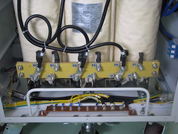
iv
Power Vault Service Manual

1       About This Manual
                        This manual provides the procedures and information required to maintain and
                        repair the Power-One 40KVA Power Vault, Teradyne part number 601-872-02.
                        It is intended for trained maintenance personnel.

                        The local Teradyne Service office can assist with any additional questions you
                        may have about Power-One Power Vault.

                        We welcome any comments or feedback you have about this manual and
                        Power-One Power Vault. Please send feedback to Teradyne Knowledge
                        Technical Support at: customercare@teradyne.com.

                        For your convenience, we have also included a Manual Comment Form at the
                        end of this manual.

                        1.1      Viewing This Manual Online
                        When viewing this manual online, you may click any hyperlink, cross-reference
                        or page number to jump to that topic.

Power Vault Service Manual                                                                           1

Part Number: 1-155462 Rev.: AB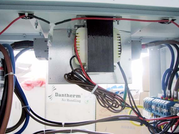
Introduction
2 Introduction
The UltraFLEX HD Test System Power-One 40KVA Power Vaults are
engineered to provide a conditioned 3-phase output of 208 volts AC to the
tester using input voltages of either 190 - 240 volts AC or 380 - 480 volts AC.
Table 1 lists the part numbers of the power vaults and applications.
Table 1 Power vault part number matrix
Tester Type Power Vault Type Power Vault P/N Teradyne P/N
UltraFLEX HD Tester 40KVA - 1Module 1-154860G 601-872-02
The 40KVA vault can be used for the UltraFLEX HD test system. The standard
power vault is designed to power a single UltraFLEX HD Tester and the
associated computer equipment.
This manual provides the procedures and information required to maintain and
repair the vaults and contains the following information:
Power Vault Overview
Unpacking
Preparing the Power Vault
Adding Input Cable and Tester Cable
Input Voltage Changeover
Testing the Vault
Closing the Vault
Schematic Drawing
Product specifications
Maintenance and Spare Parts
Ensure that you have all the necessary items required to maintain or repair the
vault prior to starting any of the procedures outlined in this manual.
NOTE Prior to performing any repairs on the Power Vault, familiarize
yourself with the information outlined in the Safety Information section of
the UltraFLEX Test System Service Manual, as appropriate. Pay
particular attention to this information as it is related to equipment
lockout-tagout.
2 UltraFLEX HD Test System Power-One 40KVA Power Vault Service Manual
Part Number: 1-155462 Rev.: AB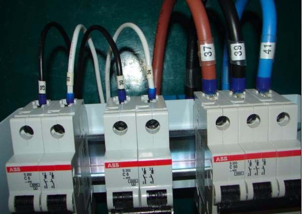
Power Vault Overview

3       Power Vault Overview
                        The Power Vault is an optional external transformer providing 3-phase 208 V
                        AC WYE configured power to the UltraFLEX HD Test System. The vault
                        contains a multiple tap, 3-phase, 36 KVA, isolation transformer T1 that
                        converts the customer's factory power, Delta or WYE, to 208 V AC, 3 phase
                        WYE that is required by the tester.

                        The Delta input of the vault can be connected to either a four wires Delta input,
                        which uses three phases and ground or a five wire WYE input, which uses
                        three phases, neutral and ground.

                        If the vault is being connected to a five wire WYE source, the main input
                        neutral wire should terminated at the facility power circuit breaker distribution
                        box and not be connected to the vault.

                        The AC input power is connected to the input power circuit breaker CB1 inside
                        the vault. The rating of the input power circuit breaker will vary depending on
                        the input voltage that is connected to the vault.

                        The vault is designed to operate using two different input voltage ranges. Main
                        Circuit Breaker CB1 is programmable; its current rating can be changed by
                        adjusting the dip switches. The first range is designed to operate using input
                        voltages of 190 to 240 volts AC. The Main Circuit Breaker CB1 can be
                        adjusted to 100 Amp for 36 KVA vaults operating on these input voltages. The
                        second range is designed for input voltages of 380 to 480 volts AC. The Main
                        Circuit Breaker CB1 is adjusted to 60 Amp for 36 K VA vaults operating on
                        these input voltages. The breaker must be manually turned on to apply power
                        to the input of the vault transformer T1.

                        The transformer output is three phase WYE, 120 V per phase, with a neutral
                        and ground. The neutral is tied to the vault chassis ground at the transformer.
                        This provides the tester with a much lower level of noise than if the neutral line
                        was used directly out of the vault transformer.

                        This 3-phase output is distributed as follows:

                        One phase is used to supply 120 V for accessory outlets. Two phases are
                        tapped to supply 208 volts to the low voltage transformer T2 in the vault, which
                        produces 24 volts AC that is used for system control. These 24 volts controls
                        the power on contactor K1, which then supplies AC power to the test system
                        through a COR-COM brand Electro-magnetic Interference (EMI) power filter.

                        The EMI filter provides the tester with Radio Frequency Interference (RFI)
                        protection from noise and also prevents from the vault from emitting any noise
                        into the facility power lines. The contactor is self latching, which means, that
                        when 24 volts AC is applied, it uses its own contacts to stay closed and only
                        drops out when the Power Off S2 or Emergency Off (EMO) S1 switches are
                        pressed. The contactor is energized by the Power On switch S3 located at the
                        front of the vault. With the contactor energized, power is distributed to the

Power Vault Service Manual                                                                                  3

Part Number: 1-155462 Rev.: AB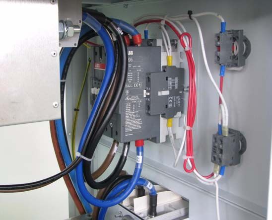
Power Vault Overview

                   output power module circuit to provide 208 volts AC that controls AC power to
                   the UltraFLEX HD Test System.

                   The vault can be powered on and tested for correct output voltage without a
                   tester or the computer equipment being connected.

                   The necessary circuit breakers and AC outlets to power the test system are
                   contained in the vault. The tester must be connected to and powered from the
                   vault.

                                   Figure 1   UltraFLEX HD 36 KVA Power Vault

                                Front View                              Back View

                           OFF Switch

                           ON Switch                             J2
                                         EMO Switch S1
                                                                J3
                                                                        CB3CB4 CB5
                                        CB1

                          CB1 DIP Switch Access Panel

                                                                                      Output

                                                                      CB6        J1    Input

4                      UltraFLEX HD Test System Power-One 40KVA Power Vault Service Manual

                                                                       Part Number: 1-155462 Rev.: AB
Unpacking
4 Unpacking
1. Unscrew the the six screws in the front door and remove them; Unscrew
the four (six) screws, four (six) nuts and eight (twelve) washers which fix
the locks and remove them. See Figure 2.
Figure 2 Unopened Crate
Lock
2. Release and open the door downward to the floor refer to Figure 3 on
page 5.
Figure 3 Opened Crate
Brake feet
Input cable
Power Vault Service Manual 5
Part Number: 1-155462 Rev.: ABPreparing the Power Vault
3. Remove the input cable by removing the two cable ties, and then
remove the output cable at the left side in the crate.
4. Loosen brake feet at the two sides of the power vault which are fixed
below the bottom panel by your feet’s stepping.
5. Pull the power vault out of the crate.
6. Remove whole the foam, packing bag and packing strip.
5 Preparing the Power Vault
This section of the manual outlines the procedures required to properly
prepare the vault for maintenance or repair.
CAUTION Implement lockout-tagout procedures prior to starting any
work on the Power Vault. Refer to the Safety Information chapter of the
UltraFLEX Test System Service Reference Manual, as appropriate for
lockout-tag out procedures.
CAUTION If lockout-tag out procedures is not enforced, place a lock on
the factory power switch once power is turned off. Retain possession of
the key until all work on the vault has been completed.
NOTE Be sure to order the appropriate replacement part(s) prior to
starting any of the procedures outlined in this manual. Part numbers for
replacement parts can be found in the UltraFLEX Test System Service
Reference Manual or in the on-line FRU Navigator.
The following tools are required to prepare the vault:
PH2 cross head screwdriver.
Adjustable torque driver capable of 13.3 in*lbs (1.5 N*m), which is used
with screwdriver bit.
11/32" socket.
Torque wrench capable of 13.3 in*lbs (1.5 N*m), which is used with 11/
32" socket.
NOTE Save all hardware removed during disassembly, it will be
required for reassembly.
6 UltraFLEX HD Test System Power-One 40KVA Power Vault Service Manual
Part Number: 1-155462 Rev.: ABPreparing the Power Vault
1. Ensure that the UltraFLEX HD Tester and Computer System have been
properly prepared, shut down and disconnected as outlined in the
Safety chapter of the UltraFLEX Test System Service Reference
Manual, as appropriate.
2. Turn off the Control Power Circuit Breaker CB6 at the rear of the vault.
3. Turn off the Main Circuit Breaker CB1 at the front of the vault.
4. Turn off the factory power circuit breaker that the Power Vault is
connected to then lock the breaker.
NOTE If at all possible, disconnect the vault from the factory power
source.
5. If the vault is installed close to the tester it may be necessary to swing
the vault away from the tester to access vault service panel.
6. While facing the front of the vault (Emergency OFF Switch - S1) identify
the left side (service panel side) of the vault. See Figure 1 on page 4.
7. Unfasten the left side panel from the vault by removing the 14 (6-32 x3/
8) screws, 14 lock washers and 14 flat washers from the panel using the
PH2 cross head screw bit and adjustable driver.
8. Remove the ground cable by removing one (8-32) nut and two tooth
washers using the 11/32" socket and torque wrench from the side panel.
See Figure 4.
Figure 4
Stud
Power Vault Service Manual 7
Part Number: 1-155462 Rev.: ABAdding Input Cable and Tester Cable
9. Lift and remove left (service) side panel from power vault.
6 Adding Input Cable and Tester Cable
6.1 Connect the input cable into power vault
The following tools are required to mount input power cable and tester cable
into power vault:
7/32" head screwdriver bit
Adjustable torque driver capable of 31 in*lbs (3.5 N*m), which is used
with screwdriver bit.
1/2" socket.
Torque wrench capable of 70.8 in*lbs (8 N*m), which is used with 1/2"
socket.
Perform the following steps to connect the input power cable to the vault:
1. Ensure that the vault, tester and computer equipment are properly
prepared as outlined in Preparing the Power Vault on page 6.
2. Loosen cable retaining nut on inlet cable entrance
3. Route one end of input power cable through retaining nut and inlet
power cable entrance as shown in Figure 5.
Figure 5 Inlet and Outlet Layout
Outlet of
tester cable
Inlet of
input power cable
8 UltraFLEX HD Test System Power-One 40KVA Power Vault Service Manual
Part Number: 1-155462 Rev.: ABAdding Input Cable and Tester Cable
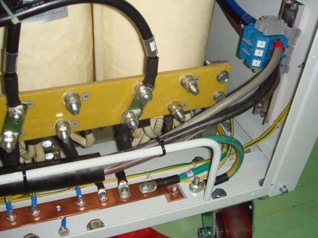
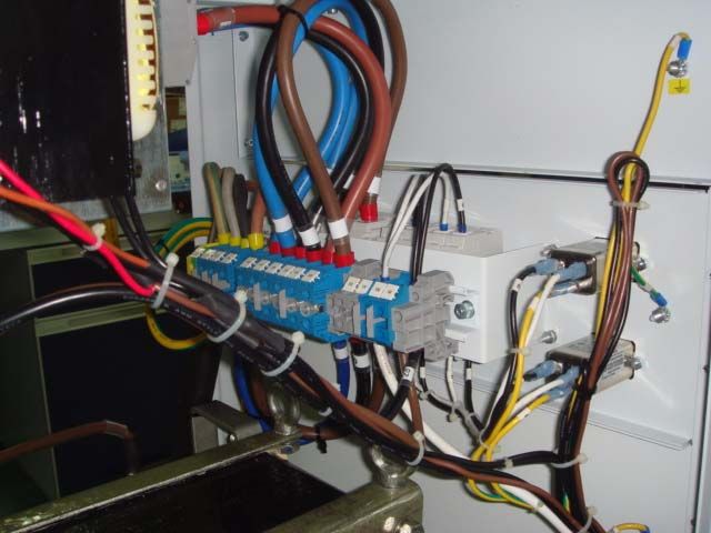
4. Connect the input power cable into terminal connections,Then tighten
the screws by using the 7/32" slotted head bit and adjustable torque
driver by torquing to 31 in*lbs (3.5 N*m) as shown in Figure 6 on page 9
.(The cable lines L1, L2 and L3 are indicated in brown, black, and grey
separately).
5. Connect the ground cable to bottom stud. Fasten the ground cable to
the stud by using the 5/16-18 nut and tighten using the 1/2" socket and
the torque wrench by torquing to 70.8 in*lbs (8 N*m) as shown in
Figure 6 on page 9.
6. Fasten the cables on the support rail with cable ties as shown in
Figure 6 on page 9.
Figure 6 Input Power Cable Connections
Gray-X1
Black-X2
Brown-X3
Ground Cable
7. Tighten cable retaining nut on inlet cable entrance.
6.2 Connect the tester cable into power vault
Perform the following steps to add tester cable to the vault:
1. Ensure that the vault, tester and computer equipment are properly
prepared as outlined in Preparing the Power Vault on page 6.
2. Loosen cable retaining nut on outlet cable exit.
3. Route one end of output power cable through retaining nut and outlet
power cable exit as shown in Figure 5 on page 8.
Power Vault Service Manual 9
Part Number: 1-155462 Rev.: ABAdding Input Cable and Tester Cable
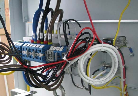
4. Connect the output power cable into terminal connections (X22 for
ground and X19, X20 and X21 for output phases). Then tighten the
screws by using the 7/32" slotted head bit and adjustable torque driver
by torquing to 31in*lbs (3.5 N*m) as shown in Figure 7 on page 10.
5. Fasten the cables to the transformer bracket with cable ties as shown in
Figure 7 on page 10.
6. Tighten cable retaining nut on outlet cable exit.
Figure 7 Tester cable connections
10 UltraFLEX HD Test System Power-One 40KVA Power Vault Service Manual
Part Number: 1-155462 Rev.: ABInput Voltage Changeover
7 Input Voltage Changeover
Changing the input voltage of the vault consists of, as a minimum, rewiring the
step down isolation transformer to accommodate the new input voltage. It may
also consist of reconfiguring the Dip switches of the Main Circuit Breaker CB1
to meet the new input voltage.
The vault is designed to operate using two input voltage ranges. The first
range is designed for the vault to operate using input voltages of 190 to 240
volts AC. The second range is designed for input voltages of 380 to 480 volts
AC.
The circuit breaker must be reconfigured when the input voltage to the vault is
changed from one range to the other.
This section of the manual outlines the following procedures:
Rewiring the Transformer.
Reconfiguring the Main Circuit Breaker-CB1.
7.1 Rewiring the Transformer
This section of the manual outlines the procedures required to rewire the
transformer in the Power Vault.
The following tools are required to rewire the transformer:
9/16" open-end wrench
9/16" socket
Torque wrench capable of 88.5 in*lbs (10 N*m) which is used with 9/16"
socket
Perform the following steps to rewire the transformer:
NOTE Save all hardware removed during disassembly, it will be
required for reassembly.
1. Ensure that the vault, tester and computer equipment are properly
prepared as outlined in Preparing the Power Vault on page 6.
2. Refer to Table 2 and determine the correct wire connections that need
to be made on the transformer to accommodate the new input voltage.
3. Remove the mounting hardware, nuts, flat washers and lock washers
from the transformer terminals that will be used when rewiring the
transformer.
4. Remove the cables from where they are already installed if necessary.
Power Vault Service Manual 11
Part Number: 1-155462 Rev.: ABInput Voltage Changeover
5. According to Table 2, Prepare the Extra jumper cables if necessary. The
extra three jumper cables are required when rewiring the transformer for
operation with 380-480 VAC input power. Extra three jumper cables as a
kit are put under the main transformer primary side, refer to Figure 8.
Figure 8 Position of extra three jumper cables
Extra three cables
6. Place the cable terminals on the transformer terminals for the new
connection needed for the transformer rewiring.
7. Secure the wires to the transformer terminals using the nut, lock washer
and flat washers which were previously removed. Place the flat washer
1st, then the lock washer and finally the nut.
8. The cables be aligned and placed so that cable terminals do not touch
each other.
9. Hold the nut that is closest to the insulator block with a 9/16" wrench.
10. Using the 9/16" socket and torque wrench fasten the cable/jumper to
the terminal by torquing the 2nd nut, the one furthest from the insulator
block, to 88.5 in*lbs (10 N*m).
11. Secure the nut, lock washer and flat washers to where they are already
removed to remove the cables and terminal is not going to be used for
the rewiring, repeat step 9 and 10.
12 UltraFLEX HD Test System Power-One 40KVA Power Vault Service Manual
Part Number: 1-155462 Rev.: ABInput Voltage Changeover
Table 2 Power vault transformer connections
Input Voltage Transformer Wire Connections Main Lines From CB1
190 B1 to G1 to A2 to F2 A2, A3, A1
B2 to G2 to A3 to F3
B3 to G3 to A1 to F1
200 C1 to H1 to A2 to F2 A2, A3, A1
C2 to H2 to A3 to F3
C3 to H3 to A1 to F1
208 D1 to I1 to A2 to F2 A2, A3, A1
D2 to I2 to A3 to F3
D3 to I3 to A1 to F1
240 E1 to J1 to A2 to F2 A2, A3, A1
E2 to J2 to A3 to F3
E3 to J3 to A1 to F1
380 F1 to B1, F2 to B2, F3 to B3 A2, A3, A1
G1 to A2, G2 to A3, G3 to A1
400 F1 to C1, F2 to C2, F3 to C3 A2, A3, A1
H1 to A2, H2 to A3, H3 to A1
416 F1 to D1, F2 to D2, F3 to D3 A2, A3, A1
I1 to A2, I2 to A3, I3 to A1
480 E1 to F1, E2 to F2, E3 to F3 A2, A3, A1
J1 to A2, J2 to A3, J3 to A1
Power Vault Service Manual 13
Part Number: 1-155462 Rev.: ABInput Voltage Changeover
Figure 9 and Figure 10 show examples of different transformer wiring
diagrams.
Figure 9 208V input voltage transformer - T1 wiring diagram
Figure 10 480V input voltage transformer - T1 wiring diagram
12. Dress the wires, then apply cable ties to secure the wires as
appropriate.
13. Once the transformer has been rewired, proceed to the section 9
Testing the Vault of this manual unless additional maintenance or repair
is required.
14 UltraFLEX HD Test System Power-One 40KVA Power Vault Service Manual
Part Number: 1-155462 Rev.: ABInput Voltage Changeover
7.2 Reconfiguring the Main Circuit Breaker-CB1
This section of the manual outlines the procedures required to reconfigure the
Main Circuit Breaker CB1 in the Power Vault.
Table 3 CB1 Information
Manufacturer Manufacturer
Components Description Name P/N Power-One P/N Teradyne P/N
Main Circuit Breaker CB1 ABB 1SDA055412R1 82100001625-G
(T4N 250 UL/CSA
PR221DA-LS/I150 3)
The following tools are required to reconfigure the Main Circuit Breaker CB1:
PH2 cross head screwdriver bit.
Adjustable torque driver capable of 13.3 in*lbs (1.5 N*m) , which is used
with screwdriver bit.
The DIP switch on the breaker CB1 can be configured so that the power vault
can be used over different input voltage ranges.
Figure 11 The Dip switch on the breaker CB1
The general Formula to adjust the current rating l1 is as below:
I1=150 x (0.4+I2+I3+I4+I5)
I2=0.04; 0
I3=0.08; 0
I4=0.16; 0
Power Vault Service Manual 15
Part Number: 1-155462 Rev.: ABInput Voltage Changeover
I5=0.32; 0
Figure 12 Input voltage range 190-240Vac (102A)
Figure 13 Input voltage range 380-480Vac (60A)
Perform the following steps to reconfigure the DIP switches, refer to Figure 14.
1. Remove the metal cover by removing the mounting screw with PH2
cross head screw bit and torque driver. Also remove the lock and flat
washers. Set hardware aside to be used when reinstalling cover .
2. Release and raise the plastic cover to the up position.
3. Refer to Figure 12 or Figure 13 for different input voltage ranges and the
correct DIP switch settings for those voltages.
4. Drop the plastic cover down and press slightly to clamp it in position.
5. Place the metal cover onto the front panel and fasten it with the screw,
lock washer and flat washer which were removed in step 1 by using
PH2 cross head screwdriver bit and adjustable torque driver. Torque the
hardware to 13.3 in*lbs (1.5 N*m).
16 UltraFLEX HD Test System Power-One 40KVA Power Vault Service Manual
Part Number: 1-155462 Rev.: ABTesting the Vault
Figure 14 Front Panel
Metal Cover Plastic Cover
8 Testing the Vault
This section of the manual outlines the procedures for testing the vault after
maintenance or repair has been performed.
The following tool is required to test the vault:
The AC Volt meter capable of bigger than 300V RMS.
Perform the following steps to test the vault, refer to Figure 1 on page 4 and
Figure 7 on page 10:
1. Ensure that all circuit breakers on the vault are in the OFF position.
2. If previously disconnected, reconnect the Power Vault to the factory
power source.
3. Turn on the factory power circuit breaker that the Power Vault is
connected to.
4. Remove any lockout-tagout devices attached to the vault.
5. Turn on the Main Circuit Breaker CB1 at the front of the vault.
6. Turn on the Control Power Circuit Breaker CB6 at the rear of the vault.
7. Insert the key into the Emergency OFF Switch S1 at the front of the
vault and turn the key to unlock the switch (the switch should release.)
8. Push the green Power ON Switch at S3 at the front of the vault, the
switch will illuminate.
9. Turn on the three (3) Auxiliary Circuit Breakers CB3 (120 V AC), CB4
(120 V AC), CB5 (208VAC 3 phase) at the rear of the vault.
Power Vault Service Manual 17
Part Number: 1-155462 Rev.: ABClosing the Vault
10. Using an AC volt meter, confirm that 24 volts AC is present at the Outlet
Receptacle J1 at the rear of the vault:
11. Using an AC volt meter, confirm that 197.6-218.4 volts AC is present
between each two of three terminals X19, X20, X21 which control by
CB5 at the rear of the vault.
12. Using an AC volt meter, confirm that 114-126 volts AC is present
between each terminal X19, X20, X21 and X22 which control by CB5 at
the rear of the vault.
NOTE Be sure to check the tester power for the appropriate voltage/
phase reference to the neutral pin. Refer to step 12.
13. Once the vault has been tested, proceed to the Closing the Vault section
of this manual.
9 Closing the Vault
This section of the manual outlines the procedures required to close the vault
after maintenance and repair has been performed.
The following tools are required to close the vault:
PH2 cross head screwdriver bit.
Adjustable torque driver capable of 13.3 in*lbs (1.5 N*m), which is used
with screwdriver bit.
11/32" socket.
Torque wrench capable of 13.3 in*lbs (1.5 N*m), which is used used with
11/32" socket.
Perform the following steps to close the vault:
1. Reconnect the green and yellow ground wire to the left side panel.
Secure the wire to the panel using the tooth washer and nut (8-32) that
were previously removed. Torque the hardware to 13.3 in*lbs (1.5 N*m)
using the 11/32î socket and the torque wrench.
2. Reassemble the side panel to the vault using the crossed head screw14
(6-32 x3/8), lock washers and flat washers that were previously
removed from the panel. Fasten the screws by torquing them to 13.3
in*lbs (1.5 N*m) using the PH2 cross head screwdriver bit and the
adjustable torque driver.
3. If the right side panel was removed, repeat steps 1 and 2 for right side
panel.
18 UltraFLEX HD Test System Power-One 40KVA Power Vault Service Manual
Part Number: 1-155462 Rev.: ABSchematic Drawing
4. Once that vault is closed, it is ready to return to service.
10 Schematic Drawing
The schematic drawing provides more details of this system.
Power Vault Service Manual 19
Part Number: 1-155462 Rev.: ABSchematic Drawing
Figure 15 40KVA Power-One Ultraflex HD Outer Vault
20 UltraFLEX HD Test System Power-One 40KVA Power Vault Service Manual
Part Number: 1-155462 Rev.: ABProduct specifications
11 Product specifications
11.1 Electrical characteristic
Mains input:
Input voltage and current limit: 190-280VAC/100A, 390-480VAC/60A,
three phase
Frequency: 50/60Hz
Power factor:> 0.9 typical
Output:
Single phase output voltage: 120 V AC
Single phase output current limit: 6A
Three phase output voltage: 208VAC
Three phase output current limit: 100A
Power: 40KVA
Efficiency:> 95%
Figure 16 Output panel
EMO (Emergency Off) thermostat description:
Inside the power vault, there is a thermostat (MFG: TI. P/N: 17AM 022) which
is fixed on the roof, and is connected on between the EMO connector and the
power-off switch (S2). When the temperature inside the power vault reach or is
higher than 75°C (167°F), the thermostat will be changed from normal close to
open status, and then the power vault will be shut down to protect the electrical
equipment. When the temperature inside the power vault is lower than 75°C
(167°F), the thermostat will return to close status, and the PDU will be
restarted again after pushing the green power-on switch (S3).
Power Vault Service Manual 21
Part Number: 1-155462 Rev.: ABProduct specifications
The information of the thermostat:
Table 4 Thermostat Information
Manufacturer Manufacturer
Components Description Name P/N Power-One P/N Teradyne P/N
External cabinet thermostat TI 17AM022 1-155709-G 605-524-02
Figure 17 Front panel with EMO connector
The information of the EMO connector is shown in the below table:
Table 5 EMO Connector Information
Manufacturer Manufacturer
Components Description Name P/N Power-One P/N Teradyne P/N
3 pos bulkhead panel IC-DFR Phoenix 1852037 82000006409-G 605-524-00
3
3 Terminal block 3p. MSTB 2.5/ Phoenix 1777992 82000006410-G 605-525-00
3-STF-5.08
3 pos bulkhead connector IC Phoenix 1825514 82000006411-G 605-527-00
2,5/3-STGF-5,08
22 UltraFLEX HD Test System Power-One 40KVA Power Vault Service Manual
Part Number: 1-155462 Rev.: ABProduct specifications
Figure 18 Drawing of the output cable
Power Vault Service Manual 23
Part Number: 1-155462 Rev.: ABProduct specifications
EMI filter:
The AYC series filters are designed for 3-phase, four-wire, WYE wiring
applications. This filter helps better to protect electronic equipment in industrial
applications. The series offers filtering up to 150 amps maximum and complies
with International Standards including EN133200 and UL1283.
Grounding:
There are two copper bars, one on each side of the main transformer, that are
fastened to the vault bottom panel by four screws. These two ground bars are
connected together by a jumper cable. The input power ground cable is
connected to the bottom panel through a stud. The two side panels are
connected to the bottom panel through two cables and screws while all the
other panels are connected to the two copper bars. For details, please refer to
Figure 19.
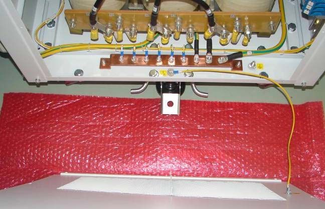
Figure 19 Ground cable connection
Mains input
ground cable
Jumper cable
Ground
for connection of
bus bar both ground bus bar
24 UltraFLEX HD Test System Power-One 40KVA Power Vault Service Manual
Part Number: 1-155462 Rev.: ABProduct specifications
Maximum inrush current:
40KVA transformer maximum inrush current:1650 A
Chart of input voltages and currents:
Figure 20 Chart of input voltage and currents
11.2 Mechanical Specification
Input/Output Cable Clamps:
Table 6 Cable clamp Information
Manufacturer
Components Description Name Manufacturer P/N Power-One P/N Teradyne P/N
Grommet CEMBRE CEMBRE 1900.M50 81500001155-G
1900.M50
Gasket for GROMMET CEMBRE 1143M50 1-154290-G
CEMBRE 1900.M50
Cable range: diameter 27 mm - 35 mm
Power Vault Service Manual 25
Part Number: 1-155462 Rev.: ABProduct specifications
Location of Center of Gravity:
The unit of dimension is millimeter in the Figure 21.
Figure 21 Location of Center of Gravity
Weight:
Vault only: 436Kg
Vault in shipping crate: 497Kg
Earthquake Protection:
The power vault has passed the SEMI S2-0703 test, an additional interlock
gives the vault the capability to be fastened to the floor, refer to Figure 22 on
page 27.
26 UltraFLEX HD Test System Power-One 40KVA Power Vault Service Manual
Part Number: 1-155462 Rev.: ABProduct specifications
Figure 22 Earthquake Protection
1 2 3 4 5 6 7 8 9 10 11 12 13 14 15 16 17 18 19 20
2
A A
B B
C C
D D
E E
F F
G G
H H
1
I I
L L
FLOOR
M M
N N
O O
3 81620000197 HEX HEAD MACH. UNC 7-16X1*1/4 2
2 3G37-241 BASE ASSEMBLY 1
1 3G37_PAV 1
POSITION COMPONENT CODE DENOMINATION QUANTITY
P P
. . . . .
DATE CHANGE DESIGNER APPROVED APPLICANT
MATERIAL TREATMENT WEIGTH kg. ROUGHNESS Q.TY
. 260654.543 1
DIMENSIONS WITHOUT INDICATION OF TOLERANCE DESIGNER APPROVED DATE
DEGREE OF GROUPS OF DIMENSIONS IN-TEC 14/09/07
PRECISION 0.5 >3 >6 >30 >120 >400 TITLE SCALE
3 6 30 120 400 1000
3 3 FINE 0.05 0.05 0.05 0.15 0.2 0.3 ENERGY STATION 3G37 1:1
X MEDIUM 0.1 0.1 0.2 0.3 0.5 0.8
Q GROSS 0.2 0.3 0.5 0.8 1.2 2 STIRRUP ASSEMBLYNG FIRST ANGLE PROJECTION Q
A0 Pro/ENGINEER
UNIT. PART. NO. ISSUE SHEET
X mm inc 3G37-271 0 1 of 1
This is an unpublished work the copyright in which rest in Power-One S.p.A. All rights reserved
this document and its information is supplied without liability for error or omissions and no
WWW.POWER-ONE.COM
party may be reproduced used or disclosed except as authorized by contract or other written
The finished product must comply with RoHS directive 2002/95/EC of the European Union. permission.
1 2 3 4 5 6 7 8 9 10 11 12 13 14 15 16 17 18 19 20
Dimension of Shipping Crate:
Height: 1435mm
Length: 970mm
Width: 805mm
Power Vault Service Manual 27
Part Number: 1-155462 Rev.: ABProduct specifications
Figure 23 Dimension of Shipping Crate
28 UltraFLEX HD Test System Power-One 40KVA Power Vault Service Manual
Part Number: 1-155462 Rev.: ABProduct specifications
Paint:
type of external paint used on vault:
FINISH: ("ORANGE PEEL EFFECT")
THICKNESS: 70-80micron
ADHESION: ISO 2409 (PETTINE 2mm) Gt0
type of finish used inside vault:
VARNISH TYPE:P/N: AC-1822
GLOSS: (60o) ISO 2813 15-25GLOSS
Describe areas that are masked, for ground bonding to cabinet chassis:
SECC areas are diameter 10mm for ground cable connection of side
panels and every front panel and rear panel.
SECC areas are square, their length and width are 35mm for two
copper ground bar.
Assembly Drawings:
Dimension of the power vault:
Height: 1084mm
Length: 704mm
Width: 524mm
Power Vault Service Manual 29
Part Number: 1-155462 Rev.: ABProduct specifications
Figure 24 Assembly Drawings
30 UltraFLEX HD Test System Power-One 40KVA Power Vault Service Manual
Part Number: 1-155462 Rev.: ABMaintenance and Spare Parts
11.3 Agency Certifications
KEMA.
11.4 Environmental Conditions
The Power vault have been designed for the following conditions:
Indoor use
Altitude up to 2000 m
Pollution degree 2
Installation category 2
Temperature:
Operating Temperature: 20°C to 30°C(68°F to 86°F)
Storage Temperature: -20°C to 80°C(-4°F to 176°F)
Humidity:
Operating Humidity: 30-85% RH non-condensing
Storage Humidity: 5-95% RH non-condensing
Acoustic Noise: < 40 dB
Vibration and Mechanical shock: Certification compliance SEMI S2
12 Maintenance and Spare Parts
Below is the list of spare parts that can be replaced during the life of the Power
Vault.
WARNING BEFORE ANY ACTION IS TAKEN ON THE POWER
VAULT THE MAIN AC MUST BE DECONNECTED FROM THE POWER
VAULT
Power Vault Service Manual 31
Part Number: 1-155462 Rev.: ABMaintenance and Spare Parts
Table 7 Spare Parts Information
Manufacturer Manufacturer
Components Description Name P/N Power-One P/N Teradyne P/N
Accessory Outlet/Filter J2 TYCO 6EBFI 82100001484-G 521-186-01
and J3
3 Pole 100A Circuit Breaker ABB SACE S293-C100 1-154804-G 605-526-00
CB5
2 Pole 6A Circuit Breaker ABB SACE S202-C6 82100001362-G 605-524-09
CB3 and CB4
24V LED replacement Lamp ABB SACE MA5-1020 82100001515-G 605-524-05
for S3
ABB EMO pushbutton switch ABB SACE CE4K1-10R-02 82100001582-G 605-528-00
S1 and keys
2 Pole 2A Circuit Breaker ABB SACE S202-K2 82100001472-G 605-524-12
CB6 ABB SACE
Main Circuit Breaker CB1 ABB-SACE 1SDA055412R1 82100001625-G 605-524-13
(T4N 250 UL/CSA
PR221DA-LS/I150 3)
Power-Off Pushbutton(red) ABB-SACE MP1-20R 82100001459-G 605-524-06
S2
Power-On Pushbutton ABB-SACE MP1-21G 82100001455-G 605-524-14
(green) S3
Contactor K1 A95 w/CAL ABB-SACE A95-30-11 82100001475-G 605-529-00
18-11 aux contact
External cabinet thermostat T1 17AM022 1-155709-G 605-524-02
75 Deg.
Power Output Cable Power One 1-154805-G 1-154805-G 605-524-01
3 pos bulkhead panel Phoenix 1852037 82000006409-G 605-524-00
IC-DFR 3
3 Terminal block 3p. MSTB Phoenix 1777992 82000006410-G 605-525-00
2.5/3-STF-5.08
3 pos bulkhead connector IC Phoenix 1825514 82000006411-G 605-527-00
2,5/3-STGF-5,08
The following tools are required to replace the parts in the vault:
PH2 cross head screwdriver bit.
32 UltraFLEX HD Test System Power-One 40KVA Power Vault Service Manual
Part Number: 1-155462 Rev.: ABMaintenance and Spare Parts
11/32" socket.
7/32" Hex head bit.
5/32" Hex head bit.
1/8" slotted head screw bit.
Adjustable torque driver capable of 13.3 in*lbs (1.5 N*m), 8.9 in*lbs (1.0
N*m), 24.8 in*lbs (2.8 N*m), 17.7 in*lbs (2.0 N*m), 62.0 in*lbs (7.0
N*m), 159.3 in*lbs (18.0 N*m), 26.6 in*lbs (3.0 N*m), 6.2 in*lbs (0.7
N*m) , which are used with screwdriver and Hex head bits.
Torque wrench capable of 13.3 in*lbs (1.5 N*m), which is used with 11/
32" socket.
NOTE The numbers showed in the picture below during replacing the
spare parts indicate wires.
12.1 Replacing Accessory Outlet/Filter J2 and J3
Filter J2 and J3 are a screw-mount type and located on the output panel of
power vault, see details in Figure 25.
Figure 25 Output panel connection
J2
43 44 Din bar support
45
EMI filter
J3
46 47
48
Perform the following steps to replace the Accessory Outlet/Filter J2 and J3:
Power Vault Service Manual 33
Part Number: 1-155462 Rev.: ABMaintenance and Spare Parts
Removal
1. Remove the right side panel as outlined in Preparing the Power Vault on
page 6.
2. Unplug the 3 wires on the EMI filter. Unplug wires 43, 44 and 45 if
removing Filter J2 and unplug wires 46, 47 and 48 if removing Filter J3.
3. Unscrew 2 (5-40 x 1/2) screws with PH2 cross head screwdriver bit and
adjustable torque driver, then adjustable torque driver, then remove 2
(5-40) nuts, 2 lock washers, 2 flat washers and 2 screws on both side of
the filter.
4. Remove the filter from Output panel.
Installation
1. Put the new filter into output panel.
2. Fasten the filter with the 2(5-40) nuts, 2 lock washers, 2 flat washers
and 2 (5-40 x1/2) screws, and torque the 2 screws to 8.9 in*lbs (1.0
N*m) using the PH2 cross head screwdriver bit and adjustable torque
driver.
3. Plug 3 wires on the filter as indicated cable number in Figure 25 on
page 33. Plug wires 43, 44 and 45 if installing Filter J2 and plug wires
46, 47 and 48 if installing Filter J3.
4. install the right side panel as outlined in Closing the Vault on page 18.
12.2 Replacing the Circuit Breaker CB3, CB4, CB5
The breaker is a din-mount type and located on the output panel of power
vault, see details in Figure 27, Figure 28 on page 38.
34 UltraFLEX HD Test System Power-One 40KVA Power Vault Service Manual
Part Number: 1-155462 Rev.: ABMaintenance and Spare Parts
Figure 26 Output Panel
52
27 26 25
Ground wire
Power Vault Service Manual 35
Part Number: 1-155462 Rev.: ABMaintenance and Spare Parts
Figure 27 Breaker Mounting
100A Circuit Breaker CB5
29 33 30 34 37 39 41
6A Circuit Breaker
CB3 and CB4
51 50 49 47 46 44 43
Perform the following steps to replace the Circuit Breaker CB3, CB4, CB5:
Removal:
1. Remove the right side panel as outlined in Preparing the Power Vault on
page 6.
2. Remove separately the wires 25, 26, 27 and 52 from the terminal X14,
X16, X18 and X22 by unscrewing the screw on the terminal using the
PH2 cross head screwdriver bit and adjustable torque driver. Refer to
the Figure 27 on page 36.
3. Unplug the ground wires 45 and 48 on the EMI filter.
4. Remove the green and yellow ground wire by removing one (8-32) nut
and two tooth washers using the 11/32" socket and torque wrench from
the output panel assembly. Refer to Figure 27 on page 36.
5. Unfasten the output panel assembly from the vault by removing 4 (10-24
x 3/8) screws, 4 lock washers and 4 flat washers from the panel using
the PH2 cross head screwdriver bit and adjustable driver. Cut the cable
ties which stop the output panel to be taken out, then lift and remove the
output panel assembly.
36 UltraFLEX HD Test System Power-One 40KVA Power Vault Service Manual
Part Number: 1-155462 Rev.: ABMaintenance and Spare Parts
6. Remove the Din bar support by removing totally 4(8-32) nuts, 4 lock
washers and 4 flat washers from panel with 11/32" socket and torque
wrench. Refer to Figure 27 on page 36.
7. Remove the wires that are connected to the breaker by unscrewing the
screws of breaker with PH2 cross head screwdriver bit and adjustable
torque driver. Remove the wires 29, 33, 43 and 44 if removing CB3;
remove the wires 30, 34, 46 and 47 if removing CB4; remove wires 37,
39, 41, 49, 50 and 51 if removing CB5. Remove the breaker from the
Din bar by pulling the handle of breaker.
Installation:
1. Put the new breaker on the Din bar and press it to fix, reconnect the
wires into breaker connection points as indicated wire number in
Figure 27 on page 36 and Removal step 7, then tighten the screw of
breaker by using PH2 cross head screwdriver bit and adjustable torque
driver by torquing to 24.8 in*lbs (2.8 N*m),
2. Install the Din bar support on the panel by installing 4 (8-32) nuts, 4 lock
washers and 4 flat washers on panel with 11/32" socket and torque
wrench by torquing to 13.3 in*lbs (1.5 N*m).
3. Reassemble the output panel assembly to the vault using 4 (10-24 x 3/
8) screws, 4 lock washers and 4 flat washers that were previously
removed from the panel. Fasten the screws by torquing them to 26.6
in*lbs (3 N*m) using the PH2 cross head screwdriver bit and the
adjustable torque driver.
4. Reconnect the green and yellow ground wire to the output panel.
Secure the wire to the panel using the tooth washer and nut that were
previously removed. Torque the hardware to 13.3 in*lbs (1.5 N*m) using
the 11/32î socket and the torque wrench.
5. Plug the ground wires 45 and 48 on the EMI filter according to the
Figure 25 on page 33.
6. Reconnect the wires 25, 26, 27 and 52 into terminal connections as
instruction in Removal step 2. Then tighten the screws by using the 7/
32" slotted head bit and adjustable torque driver by torquing to 31 in*lbs
(3.5 N*m).
7. Fasten the wires by using cable ties on proper position.
8. Install the right side panel as outlined in Closing the Vault on page 18.
Power Vault Service Manual 37
Part Number: 1-155462 Rev.: ABMaintenance and Spare Parts
12.3 Replacing 24V LED Lamp
The LAMP is a plug-mount type and is located on the front high panel, see
details in Figure 28.
Figure 28 Lamp mounting
Catch
Lamp block
24V LED
replacement lamp
Perform the following steps to replace the 24V LED lamp:
Removal:
1. Remove the left side panel as outlined in Preparing the Power Vault on
page 6.
2. Take apart lamp block from the support by prizing the catch up one side
of lamp block, and then unplug the lamp.
Installation:
1. Plug the new lamp, and then press the lamp block to fix it on the
support.
2. Install the left side panel as outlined in Closing the Vault on page 18.
38 UltraFLEX HD Test System Power-One 40KVA Power Vault Service Manual
Part Number: 1-155462 Rev.: ABMaintenance and Spare Parts
12.4 Replacing ABB EMO pushbutton switch S1
The switch S1 is a panel-mount type and located at the front high panel, see
details in Figure 29:
Figure 29 Switch mounting
Switch S1
74
75
Perform the following steps to replace the SWITCH CE4K1-10R-02 ABB:
Removal:
1. Remove the right side panel as outlined in Preparing the Power Vault on
page 6.
2. Unscrew 2 screws by using the PH2 cross head screwdriver bit and
adjustable torque driver and remove the wires74, 75.
3. Hold the switch S1 outside the panel and turn the gasket
counterclockwise to release it, and then remove the switch S1 from the
panel.
Installation:
1. Mount the new switch to the panel.
2. Reconnect the wires 74, 75 to the switch connection point and fasten 2
screws by torquing them to 17.7 in*lbs (2 N*m) using the PH2 cross
head screwdriver bit and the adjustable torque driver.
3. Install the right side panel as outlined in Closing the Vault on page 18.
Power Vault Service Manual 39
Part Number: 1-155462 Rev.: ABMaintenance and Spare Parts
12.5 Replacing 2A Circuit Breaker CB6
The Breaker is a din-mount type and located on the rear low paned of power
vault, refer to Figure 30.
Figure 30 Breaker mounting
Black Wires
Breaker CB6
18 19
Perform the following steps to replace the 2A Circuit Breaker CB6:
Removal:
1. Remove the right side panel as outlined in Preparing the Power Vault on
page 6.
2. Remove the Din bar support by removing totally 4(8-32) nuts, 4 lock
washers and 4 flat washers from panel with 11/32" socket and torque
wrench.
3. Remove the two black wires and wires 18, 19 that are connected to the
breaker by unscrewing the screws of breaker with PH2 cross head
screwdriver bit and adjustable torque driver, then remove the breaker
from the Din bar by pulling the handle of breaker.
Installation:
1. Mount the new breaker on the Din bar and press it to fix, then reconnect
the cable as indicated cable number in Figure 30 by tightening the
screw of breaker.
2. Torquing to 24.8 in*lbs (2.8 N*m)with PH2 cross head screwdriver bit
and adjustable torque driver.
3. Install the Din bar support on the panel by installing 4 (8-32) nuts, 4 lock
washers and 4 flat washers on panel with 11/32" socket and torque
wrench by torquing to 13.3 in*lbs (1.5 N*m).
4. Install the right side panel as outlined in Closing the Vault on page 18.
40 UltraFLEX HD Test System Power-One 40KVA Power Vault Service Manual
Part Number: 1-155462 Rev.: ABMaintenance and Spare Parts
12.6 Replacing the Contactor K1 A95 w/CAL18-11 aux
contact
The contactor is a screw-mount type and located on the front high panel of
power vault, refer to Figure 31.
Figure 31 Contactor Replacement
67 69
65
66
14 15 17
20 21 22
Nut (8-32)
Power Vault Service Manual 41
Part Number: 1-155462 Rev.: ABMaintenance and Spare Parts
Perform the following steps to replace the contactor K1 A95 w/CAL18-11 aux
contact.
Removal:
1. Remove the left side panel as outlined in Preparing the Power Vault on
page 6.
2. Unfasten the high front panel assembly from the vault by removing 8
(10-24 x 3/8) screws, 8 lock washers and 8 flat washers from the panel
using the PH2 cross head screwdriver bit and adjustable driver. release
the panel and show up the contactor.
3. Remove wires 14,15,17,20, 21, 22 in turn by unscrewing the screws of
contactor with 5/32" Hex head bit and adjustable driver, and remove the
67, 69, 65, 66 in turn by unscrewing the screws of contactor with PH2
cross head screwdriver bit and adjustable driver from contactor.
4. Unfasten the ABB contactor from the contactor support by removing 2
(8-32) nuts, 2 lock washers and 2 flat washers with 11/32" socket and
torque wrench, then lift and remove the contactor.
Installation:
1. Install new ABB contactor onto contactor support by installing 2 screws,
2 flat washers, 2 lock washers which were removed in removal step 1
with 11/32" socket by torquing to 13.3 in*lbs (1.5 N*m).
2. Connect control cables NO.67,69,65,66 to contactor by tightening
screws with PH2 cross head screwdriver bit and adjustable driver by
torquing to 17.7 in*lbs (2 N*m); Connect cables NO. 20, 21, 22,14,15,17
to contactor by tightening screws with 5/32" Hex head bit and adjustable
driver by torquing to 62.0 in*lbs (7 N*m).
3. Reassemble the high front panel assembly to the vault using 8 (10-24 x
3/8) screws, 8 lock washers and 8 flat washers that were previously
removed from the panel. Fasten the screws by torquing them to 26.6
in*lbs (3 N*m) using the PH2 cross head screwdriver bit and the
adjustable torque driver.
4. Install the left side panel as outlined in Closing the Vault on page 18.
42 UltraFLEX HD Test System Power-One 40KVA Power Vault Service Manual
Part Number: 1-155462 Rev.: ABMaintenance and Spare Parts
12.7 Replacing the Power-off Pushbutton (red) S2 and
Power-on Pushbutton (green) S3
The Pushbutton S2 and S3 are a panel-mount type and located on the front
high panel of power vault, refer to Figure 32.
Figure 32 Pushbutton Replacement
Support
Gasket
Handle
Perform the following steps to replace the Power-off Pushbutton (red) S2 and
Power-on Pushbutton (green) S3:
Removal:
1. Remove the left side panel as outlined in Preparing the Power Vault on
page 6.
2. Push the handle of support upward and remove the support from
pushbutton.
3. Turn the gasket anticlockwise and take the pushbutton from panel.
Installation:
1. Put the new pushbutton into the hole of panel and turn the gasket
clockwise to fix the pushbutton.
2. Push the support onto the pushbutton.
3. Install the left side panel as outlined in Closing the Vault on page 18.
Power Vault Service Manual 43
Part Number: 1-155462 Rev.: ABMaintenance and Spare Parts
12.8 Replacing the Main Circuit Breaker CB1
The contactor is a screw-mount type and located on the front panel of power
vault, refer to Figure 33.
Figure 33 Mai Circuit Breaker CB1 Replacement
Nut (M4) Nut (8-32) 3
6
5 2
1
4
Upper
Below
3 2 1
6 5 4
Perform the following steps to replace the Main Circuit Breaker CB1:
Removal:
1. Unfasten the front panel assembly from the vault by removing 4 (10-24 x
3/8) screws, 4 lock washers and 4 flat washers from the panel using the
PH2 cross head screwdriver bit and adjustable driver. release the panel
and show up the CB1.
2. Remove the front panel by removing 4 (8-32) nuts, 4 lock washers and 4
flat washers from breaker support with 11/32" socket and torque
wrench.
3. Remove wires 1-6 from breaker by unscrewing the screw with 7/32" Hex
head screw bit and adjustable driver.
4. Remove the breaker from breaker support by removing 4 screws (M4),
4 lock washers, 4 flat washers and 4 nuts, hold the nut with 11/32"
socket and torque wrench, and then unscrew the screws with the PH2
cross head screwdriver bit and adjustable driver.
44 UltraFLEX HD Test System Power-One 40KVA Power Vault Service Manual
Part Number: 1-155462 Rev.: ABMaintenance and Spare Parts
Installation:
1. Install the new breaker to breaker support by installing 4 screws (M4), 4
lock washers, 4 flat washers and 4 nuts which were removed in removal
step 1, hold the nut with 11/32" socket and torque wrench, and then
tighten the screw with the PH2 cross head screwdriver bit and
adjustable driver.
2. Connect wire 1-6 to breaker, tighten the screw with7/32" Hex head
screw bit and adjustable driver by torquing to 159.3 in*lbs (18 N*m).
3. Install the front panel to breaker support by installing 4 (8-32) nuts, 4
lock washers and 4 flat washers with 11/32" socket and torque wrench
by torquing 13.3 in*lbs (1.5 N*m).
4. Reassemble the front panel assembly to the vault using 4 (10-24 x 3/8)
screws, 4 lock washers and 4 flat washers that were previously
removed from the panel. Fasten the screws by torquing them to 26.6
in*lbs (3 N*m) using the PH2 cross head screwdriver bit and the
adjustable torque driver.
12.9 Replacing the Thermostat
The thermostat is a cable-mount type and located on the roof of power vault,
refer to Figure 34.
Figure 34 Thermostat Replacement
60 mm 245 mm
A B
B
A
Perform the following steps to replace the thermostat:
Power Vault Service Manual 45
Part Number: 1-155462 Rev.: ABMaintenance and Spare Parts
Removal:
1. Remove the two side panels as outlined in Preparing the Power Vault on
page 6.
2. Disconnect one end of thermostat cable which the length is 1150mm
from power-off push button (S2) by unscrewing the screw with PH2
cross head screwdriver bit and adjustable torque driver.
3. Disconnect another end of thermostat cable which the length is 1750
mm from EMO connector by unscrewing the screw with 1/8" slotted
head screw bit and adjustable torque driver.
4. Remove cable ties which tie the cables of thermostat and remove the
thermostat with cables.
Installation:
1. Reconnect one of the new thermostat cable which the length is 1150
mm to power-off pushbutton (S2) by screwing the screw with PH2 cross
head screwdriver bit and adjustable torque driver by torquing to 17.7
in*lbs (2 N*m).
2. Reconnect one of the new thermostat cable which the length is 1750
mm to EMO connector by screwing the screw with 1/8" slotted head
screw bit and adjustable torque driver by torquing to 6.2 in*lbs (0.7
N*m).
3. Tie the cable ties.
4. Install the two side panels as outlined in Closing the Vault on page 18.
46 UltraFLEX HD Test System Power-One 40KVA Power Vault Service Manual
Part Number: 1-155462 Rev.: ABMaintenance and Spare Parts
Personal Notes
Manual Comment Form
We appreciate your feedback. Your comments are a valuable
source of information for continuous improvement in our
documentation effort. Please return this form together with a copy
of the pages of concern from the manual marked with your
comments to the address at the end of this form.
Manual Name
Document number
Revision number and date
Sender Name
Company
Job title
Address
1. Briefly, in the space below, how would you describe this manual?
2. How do you use this manual?
I read it from beginning to end.
I only read the sections that pertain to my immediate needs.
I only read the sections that pertain to my job.
I use this manual for training purposes.
I use this manual for reference purposes.
3. When you need to find information in this manual, where is the first
place that you look:
Table of Contents
Thumb through the pages until I find what I am looking for
4. How easily can you find information in this manual?
Not easily
Very easy
Power Vault Service Manual 47
Part Number: 1-155462 Rev.: ABMaintenance and Spare Parts
5. How clear is the information in this manual?
Not clear
Very clear
6. When you actually try instructions in this manual, how easily can you
follow them?
Not easily
Very easy
7. How well did you understand the product before reading this manual:
Not at all
Very well
8. After
Not at all
Very well
9. Was all of the information you needed included in this manual?
Yes
No
If not, what was missing?
10. The best aspect of this manual is:
11. If you could change one aspect of this manual, what would it be:
48 UltraFLEX HD Test System Power-One 40KVA Power Vault Service Manual
Part Number: 1-155462 Rev.: ABMaintenance and Spare Parts
Other comments:
Return to:
Teradyne, Inc.
500 Riverpark Drive, North Reading, MA 01864, USA
Attn.: Product Support Department
FAX: (978) 370-8292
Email: customercare@teradyne.com
Power Vault Service Manual 49
Part Number: 1-155462 Rev.: ABMaintenance and Spare Parts
50 UltraFLEX HD Test System Power-One 40KVA Power Vault Service Manual
Part Number: 1-155462 Rev.: ABYou can also read