EMC of Ready-Made Connecting Devices (RMCDs) - bda connectivity GmbH
←
→
Page content transcription
If your browser does not render page correctly, please read the page content below

EMC of Ready-Made Connecting Devices (RMCDs)

   Kurt Hemmerlein*, Ralf Damm, Bernhard Mund**, Miroslav Kotzev, Thomas Schmid***

                            * Federal Network Agency, Seidelstraße 49, 13405 Berlin, Germany,
                                               Kurt.hemmerlein@bnetza.de
           ** EMC Test Engineering, bda connectivity GmbH, Herborner Straße 61a, 35614 Asslar, Germany,
                                     ralf.damm@bda-c.com, bmund@bda-c.com
              *** EMC test laboratory, Rosenberger HF-Technik, Hauptstraße 1, 83413 Fridolfing, Germany,
                       Miroslav.Kotzev@rosenberger.com , Thomas.Schmid@rosenberger.com

Abstract                                                              Cable assemblies can be of coaxial, balanced or hybrid construction.
Connecting elements such as so-called “Ready-Made Connecting          Currently, cables and assemblies are not in the scope of the EMC
Devices” (RMCDs) are integral components of electronic systems in     Directive of the EU, because according to their understanding cables
their function as data and power transmitting hardware.               are “passive”. Therefore, no regional EMC requirements exist.
                                                                      However, reality is quite different.
Currently, regional regulations e.g. European Union (EU) directives
consider RMCDs as passive components and therefore as not EMC         This paper gives an overview over common EMC problems of
relevant. Nevertheless, an unwanted function of RMCDs is the          “Ready-made connecting devices”, shows the relation between cable
transport of electromagnetic interference from and towards the        qualities and emission characteristics of HDMI cable assemblies,
connected electronic systems. Additionally, RF disturbances may       provides some measurement data and describes standardized
occur by electromagnetic radiation between RMCD and the               measurement methods of common EMC measurements of balanced
environment and vice versa depending on their electromagnetic         cable assemblies
characteristics. Thus they become EMC relevant from a practical
point of view.                                                        2. EMC environment
                                                                      Compliance with the applicable regional regulations is mandatory
Using the example of HDMI cable assemblies with different
                                                                      for the use of the terrestrial frequency spectrum. This is not the case
shielding qualities, emission measurements on finished HDMI video
                                                                      with cable connections / cable networks. It is assumed that there is
systems show that the current CISPR emission limits cannot be met
                                                                      no harmful interference if the same frequencies are used for both
if the screening quality of the applied cable assembly is not
                                                                      terrestrial and wired signal transmission in the same location at the
sufficient. The screening effectiveness of the applied cable
                                                                      same time.
assemblies are tested with a standardized test procedure and the
results are correlated to the emission measurement.                   Unfortunately, cables have some properties that are responsible for
                                                                      unwanted radiation emissions, as well as for limited immunity to
Thus, a clear evidence is that RMCDs are EMC relevant for
                                                                      electromagnetic fields of wanted emissions by radio services when
completed systems and since standardized test procedures for the
                                                                      the cable is used for signal transmission.
EMC of cable assemblies are available EMC regulations should be
adapted accordingly to ensure the EMC of working systems in the       Important EMC characteristics are transfer impedance, screening
field.                                                                attenuation for coaxial cables and coupling attenuation (including
                                                                      the symmetry) for twisted pair cables, [1], [2], [3]. Depending on the
Keywords: RMCD; EMC, HDMI, cable assembly, radiated                   signal level on the cable, a certain limit for screening and / or
emission, coupling attenuation, screening attenuation, transfer       coupling attenuation is required for trouble-free system operation.
impedance                                                             A well-known interference situation in Germany is CATV versus
                                                                      aeronautical radio services. Cable networks use the same frequency
1. Introduction                                                       for television signals and aeronautical radio service. Due to poorly
In view of the coexistence of traditional cable-based communication   shielded cables and / or poorly manufactured connectors, emissions
applications and an increasing number of wired network ports of       were observed, that were more than 50 dB above the limit, [4].
multimedia equipment and new wireless communication services,         Although analogue signal transmission is no longer used, limits are
EMC characteristics are becoming more and more important. EMC         exceeded considerably also by digital CATV signal transmission.
of devices and components shall be designed to avoid harmful          The majority of EMC issues in CATV applications is caused by
interferences or disturbances between different applications.         poorly shielded TV receiver leads.
This applies especially to cable assemblies respectively RMCDs for    In the meantime, some new types of high data link connections have
the connection of all kind of electronic components.                  been developed, e.g. USB and HDMI.

           International Cable & Connectivity Symposium - Proceedings of the IWCS 2020 Virtual Conference, October 2020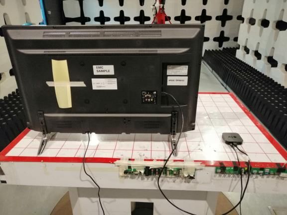
For these cable connector configurations, the EMC characteristics        It is recommended by different service providers to use at least
are also important. Unwanted emissions can disturb radio services        screening class A for interference free TV reception.
as well as multimedia applications, at least if existing CISPR limits
are exceeded.                                                            3.3 Balanced cable assemblies
Due to the capability of the new digital radio systems like channel      Balanced cable assemblies such as patch cords with RJ 45
coding and error correction, in most cases EMC issues don’t mean         connectors are widely used, e.g. for the connection of personal
that signal reception is completely impossible but the presence of       computers (PCs) to a local area network (LAN). Basic patch cords
EMI will decrease the transmission rate. The EMC characteristic of       exhibit a coupling attenuation of about 35 dB or less, mainly due to
the cable is also important for EMC tests of products. Depending on      the poorly shielded connector. Cords with better screened
the cable quality, the same product can fail or pass the test            connectors are available, e.g. for industrial applications.
procedure.                                                               Balanced cable assemblies are standardized as IEC 61935-2-n series
That is the case for both, emission as well as immunity requirements     and EN 50288-2-n series. IEC 61935-2-n series and EN 50288-2-n
and it especially happens to products in the scope of CISPR 32 and       series include construction details as well as requirements for
CISPR 35. EMC requirements are available for some types of cable         transmission characteristics and EMC limits, see table 2.
assemblies, e.g. coaxial cable assemblies of IEC 60966-2-n series         Table 2 - Coupling attenuation of balanced data cables
and for balanced patch cords of IEC 61935-2-n and EN 50288-2-n                  and assemblies acc. to IEC 61156-n series
series, but not for hybrid assemblies like HDMI cables.
                                                                            Coupling att.          Freq.                  Frequency
                                                                               type          range/requirement        range/requirement
3. Types of Ready-Made Connecting Devices                                                     30 to 100 MHz        100 to 1 000 MHz, [dB]
3.1 General
Ready-made connecting devices usually consist of a cable of a                  Type I             ≥ 85 dB          ≥ 85 – 20 × lg10 (f /100)
certain length with a connector on one or on both ends. Cables can             Type Ib            ≥ 70 dB          ≥ 70 – 20 × lg10 (f /100)
be of coaxial, balanced or hybrid construction, they may be                    Type II            ≥ 55 dB          ≥ 55 – 20 × lg10 (f /100)
unshielded or contain one or even more than one screens. For good
EMC behavior an overall screen is required.                                    Type III           ≥ 40 dB          ≥ 40 – 20 × lg10 (f /100)

The conductive shell shall be able to contact the cable overall screen   3.4 Hybrid cable assemblies
over the complete circumference with low contact resistance              Hybrid cable assemblies like USB, HDMI etc. contain different
respectively with low impedance.                                         kinds of cables, e. g. coaxial and/or balanced cables for RF signal
                                                                         transmission and insulated wires for power supply and low
3.2 Coaxial cable assemblies                                             frequency signal transmission. Preferably, they should contain an
Coaxial assemblies are the most common type of cables for RF             overall screen of braid or foil/braid construction.
signal transmission. With respect to EMC requirements, a lot of
different qualities are available on the market, see table 1. That
applies to the type of shielding (double, triple) as well as to the
junction to the connector. Unfortunately, this is not visible and also
the price is not an indicator for the quality. Only a clear
classification system with EMC requirements could be helpful for
the user. Here, the most important parameter is the screening
attenuation. The value for a good cable can be greater than 100 dB
whereas for a bad one it might be less than 30 dB. This has an
important impact on the EMC behavior of the whole system.
Table 1 – Screening classes for coaxial cable assemblies
            according to EN 60966-2-n series
     Screening- 5 - 30 MHz       30 -1000 1 GHz – 2 GHz –
     class                       MHz      2 GHz   3 GHz
                                                                          Figure 1. Assignment of the contacts of an HDMI device
     A++         0.9 mOhm/m      105 dB       95 dB     85 dB
                                                                                           socket (wikipedia)
     A+          2,5 mOhm/m       95 dB       85 dB     75 dB
                                                                         Requirements for the interfaces of hybrid cable assemblies are well
     A           5 mOhm/m        85 dB        75 dB     65 dB            described by different industrial standards or by different consortia,
     B           15 mOhm/m       75 dB        65 dB     55 dB            see e.g. https://www.hdmi.org/. Standards for RMCDs from official
                                                                         standardization organizations like IEC or CENELEC do not exist
     C           50 mOhm/m       75 dB        65 dB     55 dB
                                                                         yet. Neither exist requirements for EMC test procedures or EMC
IEC SC 46A and CLC 46XA have established screening classes for           limits
coaxial cables and cable assemblies which are standardized as IEC        Examples of different manufacturing qualities regarding the
60966-2-n series, see table 1. IEC 60966-2-n series includes             connection of the cable screen to the shell of the applied connectors
construction details as well as requirements for transmission            are shown in the figures 2a and 2b.
characteristics and EMC limits.

            International Cable & Connectivity Symposium - Proceedings of the IWCS 2020 Virtual Conference, October 2020
Thus, the equipment manufacturers and the equipment distributors
                                                                            are very interested that a good cable assembly quality is reliably
                                                                            available on the market.
                                                                            Class B requirements of CISPR 32 are intended to offer adequate
                                                                            protection to broadcast services within the residential environment.
                                                                            Class A requirements are intended for products used in industrial
                                                                            environment. Note that all equipment contain broadcast receiver(s)
                                                                            is considered to be Class B equipment.
                                                                            Table 3 shows only the requirements given in CISPR 32 (in Europe
  Figure 2a. X-ray images of HDMI connectors with poor                      EN 55032, resp.) for radiated emissions up to 1 GHz for Class B
       screen connection (Vestel EMC laboratory)                            equipment. These requirements are used in the emissions
                                                                            measurements result shown in Chapter 5. Limits up to 6 GHz can be
                                                                            found in CISPR 32.
                                                                            4.2 Screening effectiveness of cables and cable
                                                                            assemblies
                                                                            The quantities describing the screening effectiveness of coaxial and
                                                                            balanced cables and assemblies is the transfer impedance ZT in the
                                                                            lower frequency range up to about 100 MHz and the screening
                                                                            attenuation aS in the upper frequency range from 30 MHz upwards,
                                                                            depending on the length of the device under test (DUT).
 Figure 2b. X-ray images of HDMI connectors with good                       The transfer impedance ZT [mΩ/m] is defined as quotient of the
       screen connection (Vestel EMC laboratory)                            longitudinal voltage U1 induced to the inner circuit by the current I2
                                                                            fed into the outer circuit or vice versa, (see IEC 62153-4-1
To get sufficient EMC behavior, the connection of an overall screen
                                                                            respectively IEC 62153-4-3).
of an assembly shall be applied over the complete circumference of
the connector shell with low contact impedance.                             The screening attenuation aS is defined as the logarithmic ratio of
                                                                            the input power P1 to the maximum radiated power Pr,max.
4. Test procedures                                                          Screening attenuation: aS = 10 lg (P1/Pr,max)
4.1 Radiated emissions                                                      The screening effectiveness of balanced cables, connectors and
Radiated emission measurements are usually carried out according            assemblies is described among other parameters by the coupling
to CISPR 16-2-3 (2016 or 2019). CISPR 16-2-3 describes                      attenuation aC which takes into account both, the unbalance
measurement methods from 9 kHz up to 18 GHz. The measurement                attenuation aU of the pair (differential mode) and the screening
test site can be a SAC or an OATS up to 1 GHz and a FAR, a SAC,             attenuation aS of the screen (common mode).
an OATS or aFSOATS above 1 GHz.
                                                                            Coupling attenuation: aC = 10∙lg (Pdiff/Pcom) + 10∙lg (Pcom/Pr,max)
The precondition is a typical set up and an operation mode like the
intended use for the equipment as well as for the cables, especially        The unbalance attenuation aU of a balanced pair describes in
for the signal shape and level on the cables. The whole system has to       logarithmic scale how much power couples from the differential
meet the required limits.                                                   mode to the common mode and vice versa. It is the logarithmic
                                                                            ratio of the input power in the differential mode Pdiff to the power
Probably the EMC test result of the most equipment in the scope of          which couples to the common mode Pcom:
CISPR 32 (EN 55032) and CISPR 35 (EN 55035) is impacted by
the cable quality as well as by the cable arrangement. One                  Unbalance attenuation: aU = 10∙lg (Pdiff/Pcom)
requirement in CISPR 32 is: “In addition, during prescan                    Measuring of coupling attenuation of balanced cables with triaxial
measurements, the arrangement of the DUT, the arrangement of the            test set-up is described in IEC 62153-4-7 and IEC 62153-4-9.
local AE and the placement of cables shall be varied within the
range of typical and normal placement to attempt to determine the           Hybrid cable assemblies like HDMI cables consist of different
cable arrangement giving the maximum emission level.                        signal cable cores as well as of different balanced respectively
                                                                            symmetrical pairs for data transmission and clock signals. It is
   Table 3 - Requirements of CISPR 32 for radiated
                                                                            assumed that EMC emissions of HDMI assemblies at higher
emissions up to 1 GHz for Class B equipment (table A.4)
                                                                            frequencies are mainly caused by the balanced pairs, where a high
                                   Measurement            Class B limits    coupling attenuation value aC of the pair is an indication of good
Table        Frequency
                                                           [dB(µV/m)]       EMC performance.
clause      range [MHz]
                              Distance      Detector       OATS/SAC
                                [m]          type/        (see table A.1)   4.3 Triaxial test procedure
                                           bandwidth
                                                                            The triaxial test method according to IEC 62153-4-3 and IEC
              30 - 230                                          30          62153-4-4 for measuring transfer impedance and screening
 A.4.1                           10       Quasi Peak/
             230 - 1000                    120 kHz              37          attenuation was originally designed for communication cables and
              30 - 230                                          40          connectors. Meanwhile, also the measurement of coupling
 A.4.2                           3
             230 - 1000                                         47          attenuation of balanced cables and assemblies with triaxial test
 Apply only table clause A4.1 or A4.2 across the entire frequency range     set-up is described in IEC 62153-4-7 and IEC 62153-4-9, [5], [6].

            International Cable & Connectivity Symposium - Proceedings of the IWCS 2020 Virtual Conference, October 2020
In the next step, for observation of the S-parameters of the head
                                                                        and the termination adapters, one 8-port coaxial adapter and a
                                                                        short piece of HDMI cable have been used.

                                                                        One side of this short HDMI cable is clumped inside of the 8-port
                                                                        adapter and on the other side a HDMI jack is used for plugging it
                                                                        to the HDMI adapters.
    Figure 3. Coupling attenuation measurement of a
balanced cable assembly acc. to IEC 62153-4-7 - principle
IEC 62153-4-7 is currently under revision to allow balunless
measurements up to 3 GHz.
To measure coupling attenuation (as well as unbalance
attenuation) a differential signal is required.
The differential mode signal may be obtained with a 4-port vector
network analyzer (VNA) having two generators with a phase shift
of 180° using mixed mode S-parameters. The S-parameter Ssd21
(differential feeding, single ended measurement) represents the
coupling attenuation.
To connect the unbalanced ports of the VNA with the balanced
device under test (DUT) a TP-connection unit with high RF
performance is required. Furthermore, appropriate test adapters
with high RF performance are needed.
                                                                         Figure 5. Measurement set-up used for characterization
4.4 HDMI Test adapter for triaxial test set-up                             of the HDMI adapter head and for the HDMI adapter
To measure transfer impedance and screening or coupling                                termination (Rosenberger)
attenuation on balanced cable assemblies, appropriate test
adapters are required, see figure 2. The test adapters will influence
the test result and may limit the sensitivity of the test set-up.
They shall be prepared as carefully as possible.

For investigation of HDMI cable configurations using the triaxial
test method, two different dedicated test adapters have been
designed and characterized in measurements applying a 4-port
vector network analyzer. As shown in Figure 3, for triaxial test
method according to IEC 62153-4-7 one test adapter on the
generator side (see Figure 4 and 5) and one test adapter on the
receiver side are required.
It is important to note that the adapter on the receiver side acts as
a termination of the cable under test and therefore the clock and
signal pins of the HDMI connector are terminated with 50 Ohm
SMD resistors.

                                                                         Figure 6. Measured reflection of the HDMI adapter head
 Figure 4. HDMI adapter head for usage on the generator                   looking from port pair 1&3 (Sdd11) and from port pair
                  side (Rosenberger)                                                          2&4 (Sdd22)
In order to indicate the applicability of the design adapters to the    This measurement set-up allows the investigation of the head and
triaxial method several measurements have been performed in the         termination adapters as mated pair. Applying time domain gating
frequency and time domain.                                              one can remove the influence of the short HDMI cable and the 8-
The used set-up is depicted in Figure 4. As described there, in the     port adapter on the reflection loss and therefore the reflection loss
first step the VNA is calibrated up to the measurement cable ends       of the HDMI adapter only might be observed. For comparison, the
using the short-open-load-thru calibration method and mechanical        reflection parameters with and without time domain gating are
2.92 mm coaxial standards.                                              shown in Figure 6 and 7.

            International Cable & Connectivity Symposium - Proceedings of the IWCS 2020 Virtual Conference, October 2020
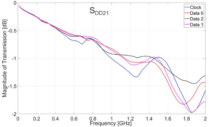
Figure 7. Gated reflection parameters of the HDMI                  Figure 9. Transmission loss of the HDMI adapter head
    adapter head looking from port pair 1&3 (Sdd11)                  These two measurement procedures allowed the characterization
The gated reflection parameters of the adapter termination           of the designed HDMI head and termination adapters. The main
obtained from the measurements are shown in Figure 8.                characteristics obtained from the studies are summarized in the
                                                                     tables below.

                                                                            Table 4 - Limits of the adapter head parameters
                                                                     Adapter head                10 MHz to     0.6 GHz to    1 GHz to
                                                                     characteristics             0.6 GHz       1 GHz         2 GHz
                                                                     Differential return loss,      > 21 dB      > 21 dB       > 18 dB
                                                                     (Z0 = 100 Ω)
                                                                     Differential                 < 0.25 dB     < 0.35 dB     < 0.6 dB
                                                                     transmission loss
                                                                     Common-mode return            > 4 dB        > 4 dB       > 4 dB
                                                                     loss (Z0=25 Ω)
                                                                     Common-mode                  < 0.23 dB     < 0.32 dB     < 0.6 dB
                                                                     transmission loss
                                                                     Unbalance attenuation,        > 30 dB       > 25 dB      > 20 dB
   Figure 8. Gated reflection parameters of the HDMI                 near end, (Scd11)
 adapter termination looking from port pair 2&4 (Sdd11)              Unbalance attenuation,        > 30 dB       > 30 dB      > 20 dB
                                                                     far end, (Scd21)
The transmission losses of the used measurement set-up (8-port
adapter + short HDMI cable) cannot be removed using time
domain gating. For this purpose, microprobe measurements have          Table 5 - Limits of the adapter termination parameters
been performed where the probe tips have been connected directly     Adapter termination         10 MHz to    0.6 GHz to 1   1 GHz to
to the footprint of the HDMI connectors on the PCBs. Looking at      characteristics             0.6 GHz      GHz            2 GHz
Figure 9, it is obvious that the main transmission loss is induced   Differential return loss,     > 25 dB       > 20 dB       > 20 dB
by the short HDMI cable and the 8-port adapter.                      (Z0 = 100 Ω)
                                                                     Common-mode return           > 9 dB        > 4 dB        > 4 dB
                                                                     loss (Z0 = 25 Ω)
                                                                     Unbalanced attenuation,      > 25 dB       > 25 dB       > 25 dB
                                                                     near end, (Scd11)

                                                                     5. Measurements
                                                                     To assess the impact of the quality of HDMI cables radiated
                                                                     emission measurements according to EN 55032 (CISPR 32), [8],
                                                                     and measurements of coupling attenuation according to IEC
                                                                     62153-4-9 respectively IEC 62153-4-7 were performed and test
                                                                     results were compared.

           International Cable & Connectivity Symposium - Proceedings of the IWCS 2020 Virtual Conference, October 2020
is 38.5 dBµV/m, i.e. at first approach, the source field could be
                                                                    about 106,5 dBµV/m.

                                                                                      radiated emission of assembly 2

   Figure 10. Test configuration for radiated emission
             measurement (Vestel EMC lab)
The test configuration for radiated emission measurements
contains a LG TV set and an Apple TV box. Different HDMI
cables were used for the connection of these devices. All other
ports were left open.
The signal provided by the Apple TV box was a moving color bar
signal and the maximum picture resolution was used [8], [9].

                  radiated emission of assembly 1

                                                                    Figure 12. Radiated emission and coupling attenuation of
                                                                                        HDMI assembly 2

                                                                                       radiated emission of assembly 3

Figure 11. Radiated emission and coupling attenuation of
                    HDMI assembly 1
The maximum values of the measured coupling attenuation of
assembly 1 are outside the diagram range of the radiated emission
measurement in the frequency range up to about 400 MHz.
With roughly calculation the coupling attenuation is about 68 dB
as an average in the range of about 400 MHz up to 1 GHz. The        Figure 13. Radiated emission and coupling attenuation of
highest measurement value of the radiated emission measurement                          HDMI assembly 3

           International Cable & Connectivity Symposium - Proceedings of the IWCS 2020 Virtual Conference, October 2020
In the range of about 400 MHz up to 1 GHz the coupling                 Therefore, it seems to be the best way to develop EMC
attenuation of assembly 2 is about 50 dB. The highest value of the     requirements for all relevant types of cables and refer to this
radiated emission measurement is 43.7 dBµV/m, i.e. at first            standard in EMC standards such as CISPR 32 as well as in user
approach, the source field could be about 93,7 dBµV/m.                 manuals. That gives the opportunity for the manufacturer to use
                                                                       this cable quality to pass the EMC product requirements as well
In the range of about 400 MHz up to 1 GHz the coupling                 for the users for an undisturbed use of the products.
attenuation of assembly 3 is about 38 dB. The highest
measurement value of the radiated emission measurement is 68,3         7. Acknowledgments
dBµV/m, i.e. at first approach the source field could be about 98,3    Special thanks to Mark Arthurs (Sony) and Cem Cengiz Keskin
dBµV/m.                                                                (Vestel EMC Laboratory) for providing the radiated emission
                                                                       measurements and for valuable advice and discussion.
It is clearly shown that the level of the unwanted emissions of the
test configuration increases if the coupling attenuation decreases.    8. References
That is nearly in the same level range and demonstrates the            [1] IEC TS 62153-4-1, Metallic communication cable test
relation between cable EMC quality and the level of the                    methods - Part 4-1: Electromagnetic compatibility (EMC) -
emissions. There is also an impact of the EMC quality of the EUT           Introduction to electromagnetic screening measurements
ports as well as the EMC quality of the whole EUT. But the             [2] IEC 62153-4-7, Metallic communication cable test methods -
quality of the cable has significantly more impact.                        Part 4 - 7: Electromagnetic compatibility (EMC)
6. Conclusions and outlook                                             [3] IEC 62153-4-9, Metallic communication cable test methods -
In this paper, the influence of cables on the level of unwanted            Part 4 - 9: Electromagnetic compatibility (EMC) - Coupling
emissions is shown using the HDMI cable as an example. That is             attenuation of screened balanced cables, triaxial method
also valid for other types of cables that are used for the             [4] Coaxial Cable Television Interference to Aviation Systems,
transmission of high frequency signals, e.g. USB.                          Eurocontrol report from 2001-03-15
                                                                       [5] Thomas Hähner, Bernhard Mund, & Thomas Schmid,
At this time, the EMC requirements of cables only play a                   History and recent trends of Triaxial test procedure,
secondary role. However, the impact of the cables contributing to          Proceedings of the 67th IWCS Conference, Providence, RI,
the emissions is visible and is increasingly changing the way we           US, October 2018
look at this issue.
Now the European EMC Directive is under revision. One of the           [6] Thomas Hähner, Bernhard Mund, & Thomas Schmid,
aims in this process is to extend the scope of the directive in such       Screening effectiveness of unscreened balanced pairs, EMC
a way that, among other things, cables are explicitly identified.          Barcelona 2019
This would make it necessary to bring up a mandate for                 [7] M. Kotzev, T. Schmid, M. Schwaiger, Time and frequency
standardization activities and demand a binding standard for               domain analysis of an 8-port adapter for multiconductor
cables.                                                                    cable screening measurements, EMC Europe 2018
Another approach is in use in the Netherlands. They introduced a
                                                                       [8] Mark Arthurs, Cem Cengiz Keskin, Radiated emission
voluntarily certification scheme KEMA Keur that is accepted by
                                                                           comparision report, Sony/Vestel EMC Laboratory
the manufacturers and by the consumers/users. Unfortunately, that
is not the case in other countries.                                    [9] Sezgin Hilavin1, Cem Cengiz Keskin, Analysis of
The consumer is mostly price driven. But the price is not even an          Repeatability and Uncertainty Issues in Radiated Emission
indicator for the quality and also the outer appearance like golden        Tests Regarding HDMI Ports, Proc. of the 2016 International
screen and pins of the connector give no evidence on the actual            Symposium on Electromagnetic Compatibility - EMC
EMC quality.                                                               EUROPE 2016, Wroclaw, Poland, September 5-9, 2016

            International Cable & Connectivity Symposium - Proceedings of the IWCS 2020 Virtual Conference, October 2020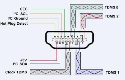
9. Authors
                                                                     Since May 2017 he is a signal integrity engineer at Rosenberger
                                 After    having    successfully     Hochfrequenztechnik. His current research interests are in the
                                 completed his apprenticeship        area of high-frequency measurement techniques, calibration and
                                 as Radio- and TV Technician         full-wave modeling of multi-layer substrates and RF devices.
                                 in 1979, Ralf Damm received
                                 his         diploma           in                                      Bernhard Mund received his
                                 Telecommunications-          and                                      apprenticeship diploma as
                                    Microprocessor-Technologies                                        Broadcast- and TV Technician
                                 at FH Giessen-Friedberg.In                                            in 1971 in Marburg, Germany
                                 1987     he    joined     bedea                                       and his diploma in Tele-
                                 Berkenhoff & Drebes GmbH,                                             communications- and Micro-
                                 working      with     electronic                                      processor-Technologies 1984
                                 development of fibre optic                                            from FH Giessen-Friedberg,
                                 components. In 2018 the bedea                                         Germany.
                                 cable division has changed to                                         Bernhard Mund has been in
bda connectivity GmbH. Later he was responsible for sales and                                          the cable business since 1985
supports for data communication networks and structured                                                when he joined the cable
cabling. He is now member of the cable R&D department and                                              manufacturer            bedea
responsible for sales & support of the CoMeT product line.                                             Berkenhoff & Drebes GmbH
                                                                                                       in Asslar, Germany.
                                 Kurt Hemmerlein started as          In 2018 the bedea cable division has changed to bda
                                 Technician responsible for the      connectivity GmbH. Formerly being R&D Manager of
                                 measurement apparatuses for         communi-cation cables, he is now head of the RF- and EMC test
                                 the German TV studio in 1979.       engineering department.
                                 In 1991, he moved to the            Besides his work for bda, Bernhard Mund has been contributing
                                 German Federal Office for Post      for more than 30 years in national and international standar-
                                 and Telecommunication (later        dization organizations.
                                 Regulatory Authority and now        He has served as Chairman of the German committee UK 412.3,
                                 the Federal Network Agency)         Koaxialkabel as well as Secretary of IEC SC 46A, Coaxial
                                 as Employee. The area of work       cables and of CLC SC 46XA, Coaxial cables, among other
                                 was the EMC of radio                standardization activities in different committees and working
                                 receivers. In 2010 he finished a    groups e.g. of the IEC TC 46 family.
postgraduate studies successful and is now responsible for EMC
issues for multimedia equipment and cable networks. Kurt is                                         Thomas Schmid received his
member of CISPR/SC/I, CENELEC TC 210 and TC 209 and                                                 apprenticeship     diploma    as
several national Committees.                                                                        Telecommunications Technician
                                Miroslav Kotzev received his                                        in 1989 and his Dipl.-Ing. (FH)
                                diploma degree in Information                                       degree in Electrical Engineering
                                Technology from the Technical                                       with emphasis on Telecommuni-
                                University of Kaiserslautern in                                     cations Technology from the
                                2004 and then worked as a                                           Munich University of Applied
                                hardware development engineer                                       Sciences in 1996. Since 1996 he
                                at Novar GmbH by Honeywell.                                         has worked at Rosenberger
                                                                                                               Hochfrequenztechnik,
                                From October 2007 to February
                                                                                                    Fridolfing, Germany, where he
                                2012 he was a research assistant
                                                                                                    is currently working as head of
                                at the Institute of Electro-
                                                                                                    EMC test laboratories. Thomas
                                magnetic     Theory at the
                                                                     Schmid has been participating in international standardization
                                Technical     University      of
                                                                     since 2006. He is member of different committees and working
                                Hamburg (TUHH), where he
                                                                     groups of the IEC TC 46 family.
received the Ph.D. degree in the field of multi-port calibration
                                                                     Thomas Schmid was granted for the 1906 IEC Award in
and high-frequency measurement techniques for signal and
                                                                     recognition of his outstanding technical contribution in
power integrity applications.
                                                                     developing, writing and finalizing TC 46’s IEC 62153-4 series
Afterwards he was a postdoctoral researcher at the Fraunhofer –
                                                                     (Metallic communication cable test methods – Electromagnetic
Institute for Electronic Nano Systems (ENAS) and the Federal
                                                                     compatibility).
Institute of Metrology (PTB, Braunschweig).

           International Cable & Connectivity Symposium - Proceedings of the IWCS 2020 Virtual Conference, October 2020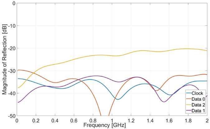
You can also read