Strategies for Operation of Controlled Auto Ignition Gasoline Engines
←
→
Page content transcription
If your browser does not render page correctly, please read the page content below
Strategies for Operation of Controlled
                            Auto Ignition Gasoline Engines
ABSTRACT
A tremendous opportunity exists for reducing fuel consumption and emissions in gasoline engines under part load
operation, with the use of a Controlled Auto Ignition (CAI) system. The start of controlled auto ignition is achieved by
reaching thermal ignition conditions at the end of compression. Chemical kinetics control the combustion process in a CAI
system, which is dramatically different from the conventional premixed combustion process. Accordingly, the
thermodynamic state determines the CAI combustion process, which can be either controlled by a high amount of residual
gas and stratification of air or residual gas and fuel.

This study utilizes the combined approach of both fundamental and application relevant aspects. Determining the
application strategy for CAI combustion requires knowledge of the auto-ignition process and its dependence on engine
operating conditions. A complete understanding of the CAI process can be obtained through a detailed thermodynamic
analysis of CAI combustion, optical diagnostics on a transparent engine and 3D-CFD analysis with reduced chemical
kinetics. Determining stability and operating range extension measures requires that detailed fundamental information is
shifted to a 1D-model, and then extended by a multi-zone approach that describes thermodynamic parameters and
incorporates reduced reaction kinetics.

A single cylinder research engine, equipped with a fully variable valvetrain and direct injection, is used to develop the
application strategies for CAI. Control over the CAI operating range can be completed through a stratification of the in-
cylinder charge. Control of stratification is possible through valve timing and a strategy for direct injection.

The necessary variability of the valvetrain for realizing CAI operation in multi-cylinder engines can be identified, based on
the thermodynamic requirements. This study uses a multi-cylinder engine with a mechanically variable valvetrain to
realize the CAI combustion process.

INTRODUCTION
Increasing fuel economy is in the primary concern for current gasoline engine development. A significant increase in fuel
economy has already been achieved by combining direct injection, reducing throttling losses with variable valvetrain
systems and boosting. Controlled auto ignition or homogeneous lean combustion is a new combustion system that shows
great potential for further reducing fuel consumption. Consideration for current as well as future emission legislation must
be made when developing new combustion systems.

Controlled auto ignition combustion (CAI) is the primary subject of this study. CAI combustion results in very low NOx
emissions, which then avoids expensive exhaust aftertreatment systems that are required for lean concepts. In relation to
conventional gasoline engines, CAI reduces throttling losses, which then leads to improved efficiency. Additionally,
reducing the combustion duration adds another benefit, which allows the design to approach the thermodynamically ideal
constant volume cycle. However, consideration must be given to the negative effect of rapid heat release on NVH
characteristics during the combustion development.

The start of CAI combustion occurs with auto-ignition during the compression stroke near TDC. Auto-ignition of gasoline
requires a specific temperature level, which is reached by internal exhaust gas recirculation. Achieving auto-ignition also
requires a valve timing strategy and a controlled stratification of the in-cylinder mixture. It is not necessary to provide
external heat for the intake air.

During previous studies, the operating range for stable CAI combustion has been determined through detailed
thermodynamic engine testing [2]. A variety of EGR strategies have to be applied (see figure 1), to optimize the CAI
operating range under the limitations that are provided.

                                                             1
Figure 1: Operating Range of the CAI Strategies Including Direct Injection and Boosting

FUNDAMENTAL INVESTIGATION METHODS

SINGLE CYLINDER EMVT CAI ENGINE

Fundamental experimental investigations of CAI combustion are done on a single cylinder research engine, equipped with
an Electromechanical Valvetrain (EMVT). The engine can be operated with Port Fuel Injection (PFI) or Direct Injection (DI).
The DI injector is in the central position. The EMVT system gives the required flexibility of valve timing as well as fast
switching times. It enables investigations of different exhaust gas recirculation strategies, Exhaust Port Recirculation (EPR)
and Combustion Chamber Recirculation (CCR). These strategies are schematically shown in figure 2. For EPR, the
exhaust valve open duration is significantly longer, so exhaust gas is drawn back from the exhaust port during the intake
stroke. For the CCR strategy the exhaust gas is kept in the combustion chamber due to a highly negative valve overlap.

                      Figure 2: Exhaust Port Recirculation (EPR) and Combustion Chamber Recirculation (CCR)

Main characteristics of the CAI single cylinder research engine:
• Single Cylinder Engine:        FEV system engine
• Bore x stroke:                 84 mm x 90 mm
• Displacement:                  0.499 dm³
• Valvetrain:                    EMVT (4 valves)
• Valve lift (In / Ex):          8 mm / 8 mm
• Compression ratio:             12
• DI injector position:          central
The investigations have been performed using commercial RON 95 grade fuel.

For the optical investigations, the engine is equipped with a transparent liner and a piston window in an elongated piston,
which provides the space for a mirror to view through the transparent piston window. The optical arrangement enables
one to visualize the combustion process with an intensified high-speed camera, providing cycle resolved information on
the UV-flame luminosity, caused by OH and CH radicals. Furthermore, the application of laser optical diagnostics is
possible, such as Particle Image Velocimetry (PIV) or Laser-Induced Fluorescence (LIF).

NUMERICAL CFD ANALYSIS
The simulation of in-cylinder flow has - during the past years - become an efficient and useful tool for the development
and investigation of new combustion systems. To understand the nature of the flow and mixture formation, gas exchange
and fuel injection have to be computed.

Meshing of the intake ports, the combustion chamber, including the piston as well as the valve motion is done using the
tool es-ice. The CFD calculation is performed using the code StarCD.

                                                                  2
The final step in CFD simulation is modeling of the combustion. Understanding when and where the auto-ignition takes
place is essential to develop combustion control strategies. Valve timing and injection are known parameters to be used
for controlling the CAI process.
For describing the auto-ignition process, a kinetic model has been developed and implemented into the CFD code [4].
Due to high computational times it is not feasible to directly implement the kinetic mechanism into the CFD domain with its
high spatial discretization, especially when simulating engine parameter variations. Hence, the reaction kinetics are
calculated in a discretization of the thermodynamic states instead of a spatial discretization. The discretization is
performed via a two-dimensional classification in the two state variables mass fraction of residual gas, YRGF, and mixture
fraction, Z. The effect of temperature is neglected in the chosen classification scheme. This has been justified in a
previous investigation, showing the existence of a strong correlation between temperature and mass fraction of residual
gas [5].
The reaction kinetic model used is that of iso-octane as a reference fuel, and is based on a reduced kinetic mechanism by
Golovitchev with 84 species and 412 reactions [3].
The coupling between the CFD code StarCD and the reaction kinetic code Cantera for a single time step is schematically
described in figure 3.
Figure 3: Coupling of 3D CFD Code and Reaction Kinetic Code
Based on the outcome of the 3D gas exchange, injection and mixture formation simulation, the cylinder charge is
classified into multiple zones by YBGF and Z. All identified zones are transferred into a reaction kinetic model. The result of
this step is the thermodynamic state and the radical composition in each specific class, and if auto-ignition occurs. The
calculated heat release of each class is mapped back into the 3D CFD. Finally, the progress of combustion can be
determined by integration of the heat release.
RESULTS OF FUNDAMENTAL INVESTIGATIONS
In the following, the fundamental processes, the interaction of charge motion, burned gas fraction, fuel stratification and
reaction kinetics are investigated for the engine operating point, NMEP = 3 bar at 2000 rpm engine speed. This operating
point has been chosen because it can be operated by both valve timing strategies, CCR and EPR. As can be seen in
figure 2, this operating point is close to the upper operating limit of CCR and close to the lower operating limit of EPR
mode. By comparing both EGR strategies, the influence of in-cylinder stratification on the auto-ignition and combustion
process can be analyzed.
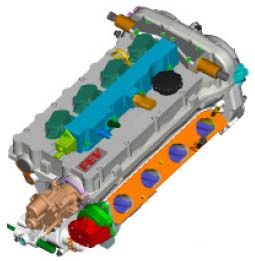
3Figure 4: UV- flame Light Evaluation, Providing the Flame Probability and Flame Contour Normal Propagation Velocity
Figure 4 shows sequences of the flame probability and flame contour propagation velocity based on the measured UV
flame light emission in CCR and EPR operation mode at 2000 rpm, 3 bar NMEP. It can be seen that for CCR the flame
probability increases over the combustion image sequence from 0 to local maxima of 0.9, which is higher than for EPR,
which reaches a local maximum of approx. 0.7. A similar observation is made for the flame contour propagation velocities
normal to the contour surface, where CCR reaches higher values than EPR. It is worthwhile noting that flame contour
propagation velocities reach values above 100 m/s, which is significantly higher than the flame propagation speed of
turbulent pre-mixed combustion in SI operation under comparable load and speed conditions.
Figure 5: Combustion Characteristics at 2000 rpm and 3 bar NMEP
Figure 5 shows test results of a residual gas fraction (RGF) -variation comparing the two EGR-strategies for an engine
speed of 2000 rpm and load of 3 bar NMEP. RGF is adjusted by changing the valve timing. The plots show the different
limits for CAI operation.
For both EGR strategies, similar limitations for CAI operation apply, as there are NVH characteristics, represented by the
maximum pressure rise limit, avoiding inefficient rich mixture, and most importantly the combustion stability limitation. A
4lower RGF leads to a lower compression end temperature and consequently a retarded combustion event. This is
indicated by a longer burn delay and burn duration, which results in higher combustion instabilities, characterized by a
higher standard deviation in NMEP.
The demand for good NVH characteristics restricts the acceptable maximum pressure gradient. Higher EGR rates result
in higher compression end temperatures and therefore in an advanced combustion with higher pressure gradients. Also
the NOx emission increases, due to higher peak temperatures. Especially important to EPR is a limitation of the maximum
RGF as the trapped air is limited and the rel. AFR should stay above stoichiometric for good fuel consumption and optimal
emissions.
For operation in CCR mode the optimum residual gas fraction is found to be between 42 and 47 %. At RGF rates above
45 %, the NOx-concentration as well as the maximum pressure gradient exceeds the defined limitation. Below 42 %, the
combustion is retarded and instable, showing NMEP standard deviations higher than
0.1 bar.
The optimum RGF range for EPR operation at this operating point is much smaller compared to CCR, and is found
between 49 and 52 %. The maximum pressure gradient is lower compared to the CCR strategy, due to a more retarded
combustion. This also causes the more unstable combustion, with NMEP standard deviations higher than 0.1 bar. Stable
combustion with higher RGF rates cannot be achieved as the mixture approaches stoichiometric state. As shown in figure
1, an NMEP of 3 bar is at the lower load limit of EPR, described by unacceptable combustion stability.
This comparison of CCR and EPR shows that EPR has a later and slower combustion, although it has a higher overall
residual gas content. This gives an indication, that different stratification effects may play a role. To better understand the
role of stratification, CFD analysis is used to quantify the degree of stratification in the combustion chamber. This
approach allows a detailed sequentially and spatially resolved insight in the mixture states of air, of residual gas and fuel
during intake and compression stroke and during the course of ignition reactions.
During the compression stroke at 90 °CA bTDC, the mass distribution of CCR shows a significantly broader range of RGF
and mixture fraction compared to EPR. However, for CCR a large part of the total in-cylinder mass is observed in zones
with relatively low RGF rates. EPR shows a broader maximum in high RGF rate zones.
Close to auto-ignition, at 10° CA bTDC, in-cylinder mixing causes a homogenization, which strongly changes the
distribution of CCR, as it concentrates around a mixture fraction of 0.025 and an RGF rate of 0.5. In comparison, EPR
shows lower homogenization, meaning a higher charge stratification.
The degree of stratification has an important effect on the auto-ignition, but even more on the subsequent combustion.
The CCR strategy is shown in Figure 6, as an example.
Figure 6: Instantaneous Mixture Fraction and Mass Fraction of OH Radicals at 10 °CA bTDC (ignition)
and at 6.4 °CA aTDC (50 % Conversion Point) for CCR Operation
5Figure 6 shows the instantaneous mass fraction of OH radicals at 10 °CA bTDC and at 6.4 °CA aTDC for CCR operation
with an RGF of 46.9%. The shown values are simulated based on the coupled CFD and reaction kinetics. It can be seen
that at the point of auto-ignition, at 10 °CA bTDC, the peak mass fraction coincides with the maximum in-cylinder mass at
a mixture fraction Z of 0.023. This indicates that the auto-ignition conditions are reached in a zone which accumulates the
highest in-cylinder mass. Hence, this leads to a high mixture conversion rate which in turn leads to a fast combustion. At
6.4 °CA aTDC, which corresponds to the point where 50% of the fresh charge is burned, a high OH mass fraction is found
in the range of Z = 0.022 to 0.028. This range coincides with the major portion of the in-cylinder charge.
Lower combustion propagation is observed on the concave side of the main combustion region due to higher rel. AFR,
and on the convex side due to leaner rel. AFR and a comparably smaller RGF, leading to reduced temperatures in this
area.
In general, the results of the fundamental investigations show that stratification of the fuel and RGF has an important
effect on auto-ignition and combustion. Hence, control of the degree of stratification enables one to adjust the auto-ignition
and combustion characteristics in CAI operation. Direct measures to control the degree of stratification are valve timing
and direct injection strategy.
Particularly for transient operating modes accurate control of the in-cylinder charge state with respect to temperature and
RGF distribution is required. On the single cylinder research engine, transient operation can be realized by appropriate
valve timing strategies, by making use of the high flexibility of the EMVT timing.
It is known that CAI combustion is affected by the temperature of the recirculated exhaust and is therefore influenced by
the previous cycle. Immediately after the transition from SI to EPR strategy, the combustion of some cycles occurs very
advanced, and is due to higher exhaust gas temperatures during the SI operation. After six combustion cycles the
combustion phasing returns to the steady-state operation results.
CAI COMBUSTION SIMULATION
Detailed understanding of the auto ignition process is required for the layout of a control strategy for the development of a
multi-cylinder CAI engine. Several approaches are used to model the engine. Reaction kinetics simulations are utilized to
investigate the auto ignition of different mixture compositions and thermodynamic states. In the following, a reduced
combustion model for fast simulation of the CAI combustion together with gas exchange simulations is presented.
CFD results of the gas exchange, injection and mixture formation are used to quantify the distribution of vaporized fuel
and residual gas in the combustion chamber. The CFD calculations are performed for various RGF rates, injection timings
and engine loads. The information about the distribution function is saved in lookup tables. This information is
subsequently used for reaction kinetic calculations. Depending on the trade-off between calculation time and accuracy the
number of zones can be chosen during the simulation. Typically the zones are initialized to be square in the two-
dimensional phase space of mixture fraction and residual gas mass fraction. A multi-zone reaction kinetic model of the
engine is utilized to simulate the high pressure cycle of the engine.
The early phase of heat release is underestimated while the end of combustion occurs a little too fast, and hence the
maximum pressure and the maximum pressure rise are slightly overestimated. However, in general the simulation results
agree well with the experiments, especially considering that the computational effort is noticeable reduced compared to
detailed CFD models. The high pressure cycle can be calculated within 2 hours on a single 2 GHz CPU.
The developed procedure allows a useful prediction of CAI combustion behavior during engine development. However,
the required computational time inhibits the direct use of the reaction kinetics simulation to predict transient operation,
which is necessary e.g. for control algorithm development, where many cycles have to be simulated in a much shorter
time.
Figure 7 shows the comparison of engine measurement and a GT-Power model using an adapted Vibe combustion model
and a single zone reaction kinetics model. Due to the fast combustion without any delay in the burn rate, a single Vibe
approach shows a good correlation to the measurement. Also cylinder pressure parameters such as peak pressure
location, NMEP etc., which can potentially be used for closed-loop combustion control, can be simulated with a sufficient
accuracy.
6Figure 7: Comparison of Engine Testing Data with GTPower Results with Vibe
and Reaction Kinetics Combustion Rate for CCR Mode at 2000 rpm and 3 bar NMEP
Additionally, a coupling of the GT-Power model with the reaction kinetics is possible. A single zone reaction kinetic
simulation can be realized without knowledge of the degree of mixture stratification. The single zone results show a lower
degree of correlation to the measurement results than the Vibe approach. Nonetheless, the peak pressure location and
the NMEP can be predicted with acceptable accuracy at reasonable computational time. This coupling can also be used
to predict the required valve timing flexibilities during the engine layout process. A simulation with more zones is currently
being developed and shows a better correlation but requires significant higher computation times.
For investigation of the engine transient behavior, several load step tests have been performed. For these load steps all
actuators are adjusted within one cycle from the previous to the next, with optimized steady-state settings. This use of
fixed steady state control parameters is especially useful for validation of the modeling approach and the control algorithm
layout. The measurement results show a noticeable transient behavior after the load steps with load increase. However,
only 4-8 cycles are necessary to return to stable operation. The GTPower simulation with a Vibe combustion model
implemented shows good correlation in steady state operation. As one can see, currently the increasing load step cannot
be predicted accurately enough, which is due to the lower exhaust gas temperature in the previous lower load point. The
ongoing investigation focuses on improving these transient conditions, using the presented strategies of CFD and reaction
kinetics simulation combined with the engine testing.
CAI COMBUSTION SYSTEM DESIGN FOR MULTI-CYLINDER ENGINE
Based on above results a multi-cylinder engine has been designed and set up to run in CAI operating modes.
Figure 8 shows the cylinder head design with a variable valvetrain. The engine is based on FEV’s 4-cylinder Spray
Guided DI Turbo (SGT) engine with 1.8L displacement and a peak power of 160 kW. As shown, the realization of different
EGR control modes is essential to enable CAI operation in a wide operational area. The turbo-charging allows extension
to higher loads, as shown in figure 1.
7Figure 8: FEV SGT Cylinder Head Design
The EGR control is realized by a dual lift roller rocker arm and dual cam phasers. The developed valvetrain offers the
capability to operate in CCR mode and also in two modes of EPR, with an early and a late exhaust gas recirculation. The
requirements for the valvetrain layout in terms of maximum valve lift, event length and cam phasing speed, have been
supported using the previously developed simulation tools, combining gas dynamic simulation with reaction kinetics.
CONCLUSION
While under part load conditions, CAI engines offer the potential to reduce fuel consumption and NOx emissions. Control
of the auto ignition process is completed through combustion chamber recirculation and early exhaust port recirculation.
The combination of multi-dimensional simulation tools and optical investigations are used to provide a basic
understanding of the CAI process. The operating limits are determined through experimentation. Meanwhile, the effect of
the control parameters valve timing and injection timing are investigated simultaneously with combined CFD and reaction
kinetic models.
The distribution and level of stratification of fuel, air and residual gas in the combustion chamber can be resolved in great
detail through numerical analysis. The stratification state has a strong impact on the combustion rate, as shown by the
reaction kinetic simulation, predicting auto ignition and the progress of combustion.
A key to the successful application of CAI combustion in future automotive applications can be found in extremely
accurate control of transient modes and shifts between different operating modes. One crucial requirement is to improve
the closed loop control of the combustion process [8]. This study utilized the approach of reduced modeling of the CAI
process, which is used to generate data to better understand the behavior of the engine during load steps, which feeds
into the control strategy. Currently, the design and setup of a multi-cylinder CAI engine is under development.
ACKNOWLEDGMENTS
The authors would like to thank the “Deutsche Forschungsgemeinschaft” (DFG) for funding this work within the framework
of the “Sonderforschungsbereich 686 – Modellbasierte Regelung der homogenisierten Niedertemperatur-Verbrennung“.
Furthermore, thanks to Dr. Jens Ewald for fruitful discussions in the field of modeling.
REFERENCES
1. Bücker, C., Stapf, K.G., Krebber-Hortmann, K., Pischinger, S., Mori, S.: Different Variable Valve Control Strategies for
Controlled Auto Ignition Optimization, HdT-Tagung Variable Valve Control, Essen, 2007
2. Pischinger, S., Bücker, C., Lang, O. , Salber, W.: Untersuchung von Ventiltriebsvariabilitäten für Brennverfahren mit
kontrollierter Selbstzündung, 7. Tagung Motorische Verbrennung, 15.-16.03.2005, München
3. Golovitchev, V.: http://www.tfd.chalmers.se
4. Stapf, K.G., Pischinger, S., Prediction of Ignition for a CAI-Engine using Multiple-0-D-Simulation, Comb.Theory Model.,
2008, submitted
5. Stapf, K.G., Seebach, D., Fricke, F., Pischinger, S., Hoffmann, K., Abel, D.: CAI-Engines: Modern combustion system
to face future challenges, SIA Int. Conf. - The Spark Ignition Engine of the Future, 28.-29.11.2007, Strasbourg
6. Adomeit, P., Jens Ewald, J., Stapf, K.G., Seebach, D., Pischinger, S.: Control and Prediction of the Stochastic Ignition
Process for a Gasoline CAI Combustion System, 8. Int. Symp. Combustion Diagnostics, 10.-11.06.2008, Baden Baden
87. Pischinger, S., Stapf, K.G., Seebach, D., Bücker, C., Adomeit, P., Ewald, J.: Controlled Auto-Ignition: Combustion Rate
Shaping by Mixture Stratification, Vienna Motor Symposium, Vienna, 2008
8. Hoffmann, K., Seebach, D., Pischinger, S., Abel, D.: Neural Networks for Modelling and Controlling Future Low
Temperature Combustion Technologies, 3rd IFAC Workshop on Advanced Fuzzy and Neural Control, Valenciennes, 2007
CONTACT
Dr. Philipp Adomeit, adomeit@fev.de
9You can also read