Analysis of a Chirp-Based Waveform for Joint Communications and Radar Sensing (JC&S) using Non-Linear Components
←
→
Page content transcription
If your browser does not render page correctly, please read the page content below
Analysis of a Chirp-Based Waveform for Joint
  Communications and Radar Sensing (JC&S) using
              Non-Linear Components
              Andre N. Barreto, Thuy M. Pham, Sandra George, Padmanava Sen and Gerhard Fettweis

                                          Barkhausen Institut, Dresden, Germany
     Email: {andre.nollbarreto, minhthuy.pham, sandra.george, padmanava.sen, gerhard.fettweis}@barkhauseninstitut.org

  Abstract—Joint communications and radar sensing (JC&S) is          approach, radar and communications are still considered as
expected to be one of the key features in beyond 5G (B5G)            separate systems, using different waveforms and equipment.
networks, allowing the provision of radar as a service (RaaS).          However, it is common knowledge that both applications
In this paper, we are interested in a chirp-based waveform that
can be effectively employed for both communication and radar         rely on the same physical phenomenon, i.e., the propagation
applications. More specifically, we investigate the performance of   of electromagnetic waves, and, therefore, both radar sensing
such a waveform in the presence of realistic non-linear power        and wireless communications could be co-designed, such that
amplifiers (PA) and low-noise amplifiers (LNA), operating at         they can share the same waveform, spectrum and hardware.
mmWave frequencies.                                                     This latter approach allows a flexible allocation of resources,
                                                                     depending on the temporal and spatial needs of each service,
                      I. I NTRODUCTION
                                                                     which results in a more efficient usage of the available
   Sensing is widely seen as one of the key technologies in          spectrum. For instance, in a busy street crossing, most of
the sixth generation (6G) of wireless communication systems          the resources can be allocated to radar, whereas at home the
[1], allowing a plethora of new services and applications. It is     spectrum can be fully allocated for communications, to allow
envisaged that radar sensing, in particular, will be integrated      communications at very high data rates. The service demands
with the communications network [2], such that it can be             may also dynamically vary over time. For example, a radar ap-
offered as an additional service upon demand, in what we             plication may consist of several distributed radars in different
call Radar as a Service (RaaS).                                      vehicles and in the infrastructure, which communicate with
   Currently, radar and wireless communication systems are           each other through an in-band broadband communications
designed and deployed separately, using different hardware           link, for interference coordination and/or sensor fusion.
and waveforms, and distinct parts of the spectrum. Consumer             One of the research challenges towards this vision is how to
radar applications, especially for the automotive industry,          design a physical layer (PHY) that is flexible, but still efficient
currently operate mostly in the 24 GHz and in the 76-                for both radar and communications. Orthogonal frequency-
81 GHz bands, with the former being discontinued soon [3].           division multiplexing (OFDM) has been proposed as a possible
Anyway, there will still be 5 GHz of spectrum being used             waveform [6], but its implementation can be rather complex
for automotive and consumer-market radar, not to mention             for the large bandwidths under consideration, and would also
the spectral allocation for aeronautical, meteorological and         require full duplexing terminals for monostatic radars.
military radar. This is nearly twice as much as the whole 5G            In fact, a chirp-based waveform can be effectively used to
spectrum currently available, including the frequencies above        achieve both functionalities. Chirps are extensively used in
6 GHz. Radar services are already extensively used in vehicles,      radar systems, because of their good ambiguity properties, but
and their usage is likely to increase with new autonomous            mostly because of the possibility of a less-complex hardware
vehicles, but this usage is currently limited to highways and        implementation, using pulse compression and lower-rate sam-
streets. Other usages of radar can be envisaged, like gesture        pling [7]. The performance of chirp signals for radar detection
recognition [4], but in most places, like homes, offices and         has been extensively studied in the literature and in text books
parks, this sizeable portion of the spectrum remains largely         [8], [9], and it will, therefore, not be addressed in this paper.
unexploited.                                                            Chirps can also be used for communications, and this is
   There have been some attempts in the literature to allow          the focus of this paper. Frequency-shift keying (FSK) mod-
the coexistence of both systems [5] in the same spectrum             ulated chirps have been proposed in [10], but, due to radar
band using cognitive-radio techniques. This approach can be          requirements, the data rate is limited by the chirp duration,
effective when we have an incumbent primary service at fixed         which is usually much larger than the inverse of the bandwidth,
locations, but it is unlikely to make full usage of the available    resulting in a low spectral efficiency. The modulation with
spectral resources in a more dynamic scenario. Also, in this         phase-shift keying (PSK) or quadrature-amplitude modulation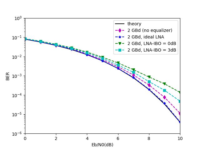
(QAM) has also been proposed in the literature [11], [12], f
but these papers consider a spread-spectrum system with low
spectral efficiency. Chirps can be overlapped to increase the
data rate, but suffer from inter-chirp interference (ICI), as B Radar Communications
the overlapping chirps are not orthogonal, except in very
specific conditions [13]. Also in [13] the bit error rate (BER)
performance of overlapping modulated chirps is derived, and
linear equalization is proposed to compensate the ISI, showing
that they can also be used close to the Nyquist signalling rates
or even faster. τc τ t
Individual chirps have constant amplitude, but the over-
lapping of chirps will increase the peak-to-average power Fig. 1. The considered Joint Communications and Sensing Systems
ratio (PAPR) of the generated signal. This will increase the
requirements on the linearity of radio-frequency (RF) circuits, with B and τc the sweep bandwidth and the chirp duration,
with a consequent increase in implementation costs and loss respectively.
of amplifier efficiency. With this in mind, in this paper we Considering an additive white Gaussian noise (AWGN)
extend the analysis of [13] to consider the effect in the system channel with a matched filter at the receiver, then the filter
performance of non-linearities in a power amplifier (PA) and output is given by
in a low-noise amplifier (LNA).
y(t) = (s(t) + w(t)) ∗ x∗ (−t) (3)
The paper is organized as follows. In Section II we present
M d −1
our chirp-based waveform concept, and in Section III we X
present details of the PA and LNA models used to model = di r(t − iτ ) + n(t), (4)
i=0
the hardware imperfections in our study. These models are
based in actual circuit design, also described in that section. where w(t) is the white Gaussian noise component with power
Simulation results using these models are discussed in Section spectral density N0 /2 and n(t) is the corresponding filtered
IV, and some concluding remarks are presented in Section V. noise component.
r(t) is the chirp autocorrelation function, which can be
II. A CHIRP - BASED WAVEFORM FOR JOINT
derived as [13]
COMMUNICATIONS AND SENSING
The proposed waveform consists of transmission frames sin πBt(1 − |t|
τc )
that can be used for radar, communications or both. At the r(t) = , |t| ≤ τc . (5)
πBt
beginning of each frame, Mp unmodulated non-overlapping If ideal synchronization is considered, the output of the
chirps are transmitted. These can be employed for radar matched filter at the time tk = kτ is, therefore,
detection, but can also serve as a preamble for the com-
Md −1
munications part of the frame, facilitating synchronization X
yk = di r ((k − i)τ ) + nk = dk + vk + nk , (6)
and channel estimation. The number of preamble chirps is
i=0
variable, depending on the requirements of a possible radar
application. The preamble is followed by a sequence of Md where nk = n(kτ ) and
PSK/QAM-modulated chirps transmitting data. The number M
X d −1
of modulated chirps depends of course on the requirements vk = di r((k − i)τ ) (7)
from the communication application, but we can also vary the i=0
i6=k
interval between adjacent chirps. As shown in [13], shorter
intervals increase the spectral efficiency, but also result in is the interchirp interference (ICI).
more inter-symbol interference among chirps, requiring more In [13] the authors have proposed a simple linear block
complex equalization techniques. The interval can thus be equalizer to compensate for the ICI. This equalizer can be
adapted to the BER and data-rate requirements of the particular easily designed utilizing the closed-form interference matrix.
application. This concept is depicted in Fig. 1. For a given frame, the sampled received signal can be
As mentioned before, we focus on the communications part represented as vector y = [y0 , y1 , . . . , yMd −1 ]T , given by
of the proposed waveform, which can be modelled as y = Hd + n, (8)
Md −1
where d = [d0 , d1 , . . . , dMd −1 ]T , n = [n0 , n1 , . . . , nMd −1 ]T
X
s(t) = di x(t − iτ ), (1)
i=0
and the interference matrix H is defined as
where di are complex-valued data symbols, with E |di |2 =
r0 r−1 · · · r−(Md −1)
Es . x(t) is an up-chirp pulse, which in baseband is given by
r1 r0 · · · r−(Md −2)
H= , (9)
.. .. .. ..
1 . . . .
x(t) = ejπB (−1+ τc t ) , 0 ≤ t < τc ,
t 2
(2) rMd −1 rMd −2 ··· r0
τcwhere rk = r(kτ ). the gain stage using cascade device configuration. Both input
With this model, we can apply simple linear block equaliza- and output ports are matched to 50 Ω. The inter-stage tuning
tion methods, for example, zero-forcing (ZF). Considering the and the output matching are both realized using transmission
eigenvalue decomposition H = UΣUT , then the transmitted lines. The transmission lines used in the design are high-
data sequence can be estimated as Q coplanar waveguide transmission lines with shielding. The
sizing of the transistors is done to reduce the noise contribution
d̂ = H−1 s = UΣ−1 UT s (10) of each transistor by biasing it close to the current-gain cutoff
It was also shown in [13] that minimum mean-square error frequency fT [15]. The LNA is tuned to the specific bandwidth
(MMSE) equalizer can also be employed, albeit with a negli- to avoid out-of-band signals influencing the receiver chain, as
gible performance gain. it is almost impossible to integrate input filters after antenna
at these frequencies.
III. M ODELING OF H ARDWARE I MPERFECTIONS
In this section we describe the non-linearity models for both Vdd
LNA and PA that are used in our simulations.
Most communication systems today utilize a carrier fre- Vdd
quency below 10 GHz, even though automotive radars have Td3 C3
been realized in 76-81 GHz. Due to overcrowded bands below
10 GHz, increasing complexity and limiting performance, Td1 Td2 Vout
there is a constant push to go to millimeter wave (mmWave)
bands for communication devices. MmWave frequencies (by C1 M3
definition, above 30 GHz) may bring new frequency spectrum M1 C2
to use, but they will bring more challenges to be solved Vin Lg
M2
as well, namely, need of phased arrays to compensate for R1 R2
path losses, additional parasitic components in realization
and additional development costs for advanced processes to Vb1 Ts1 Ts2
Vb2
fabricate the hardware. In order to reduce the development
costs of hardware, and to overcome the limitations of devices
at those frequencies, system co-design should be given highest
Fig. 2. 61GHz LNA Schematic
priority. This will not only reduce the development cycles but
it will provide a better optimized system. In our current work,
the hardware performances are considered and integrated in B. Power amplifier
the analysis, keeping the co-design principles in mind. The schematic of the power amplifier is shown in Fig. 3. The
We have chosen a 2 GHz band around 60.48 GHz as one 2-stage power amplifier is realized using common source con-
of the mmWave bands under consideration. Bands around figuration with source degeneration in both stages. Coplanar
60 GHz have been long considered for communication sys- waveguide transmission lines with ground shielding are used
tems, e.g., under IEEE 802.11ad [14] standard. More recently, for all matching. The transistors are matched to deliver higher
besides 5G discussions, the 60 GHz band is also used for power outputs over a very wide bandwidth and the transistor
motion-sensing and gesture control applications in commercial gain roll-off is not fully compensated to avoid narrow-band
products. Thus, this band is a strong candidate for research in performance.
joint communication and sensing domain.
Two front-end blocks are considered in our hardware mod- C. LNA and PA simulation results
els, a low noise amplifier and a power amplifier for low-power Fig. 4 depicts the frequency response plots of both LNA and
transceiver realization. The circuits are realized in 22 nm fully PA. The LNA reports a gain of 22 dB and the PA achieves
depleted silicon-on-insulator (FDSOI) process from Global a gain of 8.8 dB at 61 GHz. The low-noise amplifier draws
Foundries. The device layouts are extracted and post-layout a total 20 mA current from a 0.8 V supply providing 4.6 dB
simulations are considered here. Their design principles and noise figure and 19 dB gain over a 3 GHz bandwidth. The
simulated behaviour are presented below. 1 dB bandwidth of the wideband PA is larger than 5 GHz.
Fig. 5 shows the AM/AM conversion model of both LNA
A. Low-noise amplifier
and PA, including their 1 dB compression point (P1dB ).
Fig. 2 shows the schematic of a two-stage single-ended The LNA achieves P1dB = −18.34 dBm output. The power
LNA. The amplifier utilizes inductive degeneration in both amplifier draws 22 mA current from 0.8 V yielding P1 dB =
stages to increase stability and ease of matching for devices. −4 dBm and 8 dBm saturated output power.
The input matching is realized by an inductive transmission
line. Inductive degeneration improves the linearity by forming IV. S IMULATION R ESULTS
a negative series feedback. The input stage uses common- We have simulated the waveform and equalizer presented in
source for better noise performance, and the second stage is II, considering the PA and LNA models described in Section100
Vdd
Vdd
Td3 C3
10−1
Td1 Vout
CCDF
Td2
C1
M1 C2
Vin Lg 10−2
M2
R1 R2
B = 100MHz, R = 1MBaud
B = 100MHz, R = 50MBaud
Vb1 Ts1 Ts2 B = 2GHz, R = 1GBaud
Vb2
10−3
−10 −5 0 5 10
Fig. 3. 61GHz PA Schematic Instant-to-Average power ratio (dB)
Fig. 6. Empirical distribution of the instant transmit power
0
Normalized gain (dB)
III. As mentioned before, we focus on the communications
−5 performance of the proposed JC&S waveform, and consider
perfect synchronization and a single-path channel without
−10 fading. No channel coding is considered in all simulations,
and we transmit frames consisting of Md = 1000 data symbols
−15 LNA each.
PA
In this whole section we consider chirps with length 1 µs,
−20 with bandwidth either B = 100 MHz or B = 2 GHz. Results
50 55 60 65 70 were obtained with our link-level simulator HermesPy [16].
Frequency (GHz) First, though, we investigate the power variation of the
transmitted signal with different parameters, since this is the
Fig. 4. Frequency response of PA and LNA main factor affecting the performance with non-linear devices.
In Fig. 6 we display the empirical complementary cumulative
distribution function (CCDF) of the instant power ratio, as
a ratio to the average power, with BPSK modulation. As
LNA expected, we notice that non-overlapping chirps (symbol rate
PA R = 1 Mbaud) have a constant amplitude, and that the signal
20 P1dB presents a larger variation of the instant power as the number
Output power (dBm)
of overlapping chirps Nol = dτc /τ e increases.
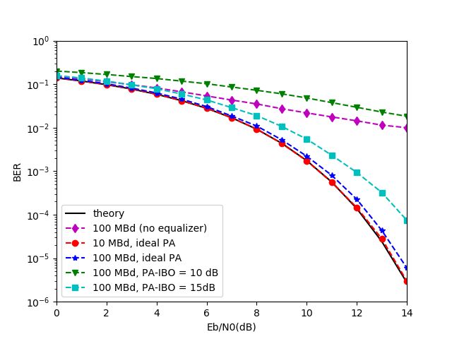
In Fig. 7 we simulate a system with bandwidth B =
0 100 MHz and 16-QAM modulation, with different symbol
rates Rs , and display its bit error rate (BER). For a symbol
rate Rs > 1/τc the chirps will overlap, with a consequent
interchirp interference (ICI). We show the performance with-
−20 out equalization to show the effect of ICI. However, a simple
ZF block equalizer can effectively compensate ICI, attaining
the same performance as the theoretical performance in an
−40 AWGN channel for Rs = B/10 = 10 MHz, or just with a
small performance loss, even at the Nyquist signalling rate,
−40 −30 −20 −10 0 10
Rs = B = 100 MHz. Unless otherwise stated, all other BER
Input power (dBm)
curves in this paper consider ZF equalization. .
Fig. 5. AM/AM conversion model of PA and LNA (1 dB compression point Further, we simulated the effect of a non-linear PA, fol-
marked) lowing the model from Section III-B. We have simulated
with different input backoff (IBO) values, defined as theLNA backoff, when compared with the PA impairments.
V. C ONCLUSIONS
In this paper we have presented a chirp-based waveform,
that, in addition to radar detection, can also be used for
data transmission. Such a waveform can be a key enabler for
offering radar as a service in future wireless communications
systems, and understanding its performance including realistic
hardware realizations is essential. With that in mind, we have
presented the circuit design of a suitable power amplifier
and a low-noise amplifier , with the corresponding non-
linear behaviour. The performance of the chirp waveform was
simulated using these circuits, allowing us to derive some
design guidelines for future chirp-based joint communications
and sensing systems.
R EFERENCES
Fig. 7. System performance with τc = 1 µs, B = 100 MHz, 16-QAM (ideal [1] C. de Lima et al., “6G white paper on localization and sensing [white
LNA) paper],” . University of Oulu, Tech. Rep. 6G Research Visions, No. 12,
Jun. 2020. [Online]. Available: http://urn.fi/urn:isbn:9789526226743
[2] F. Liu et al., “Joint radar and communication design: Applications, state-
of-the-art, and the road ahead,” IEEE Transactions on Communications,
vol. 68, no. 6, pp. 3834–3862, 2020.
[3] W. Buller et al., “Radar congestion study,” National Highway Traffic
Safety Administration, Tech. Rep. DOT HS 812 632, Sep. 2018.
[4] B. Dekker et al., “Gesture recognition with a low power fmcw radar
and a deep convolutional neural network,” in 2017 European Radar
Conference (EURAD), 2017, pp. 163–166.
[5] L. Zheng, M. Lops, Y. C. Eldar, and X. Wang, “Radar and communi-
cation coexistence: An overview: A review of recent methods,” IEEE
Signal Processing Magazine, vol. 36, no. 5, pp. 85–99, 2019.
[6] C. Sturm and W. Wiesbeck, “Waveform design and signal processing
aspects for fusion of wireless communications and radar sensing,”
Proceedings of the IEEE, vol. 99, no. 7, pp. 1236–1259, 2011.
[7] I. Bilik, O. Longman, S. Villeval, and J. Tabrikian, “The Rise of
Radar for Autonomous Vehicles: Signal processing solutions and future
research directions,” IEEE Signal Processing Magazine, vol. 36, no. 5,
pp. 20–31, 2019.
[8] M. Richards, Principles of Modern Radar: Basic Principles (1st Edi-
tion). Scitech Publishing, 2010.
[9] B. R. Mahafza, Radar Systems Analysis and Design Using Matlab (3rd
Edition). CRC Press, 2013.
[10] S. Dwivedi, A. N. Barreto, P. Sen, and G. Fettweis, “Target de-
Fig. 8. System performance with τc = 1 µs, B = 2 GHz, Rs = 2 GBd tection in joint frequency modulated continuous wave (fmcw) radar-
QPSK (ideal PA) communication system,” in 16th International Symposium on Wireless
Communication Systems (ISWCS), 2019, pp. 277–282.
[11] A. Springer et al., “A wireless spread-spectrum communication system
using SAW chirped delay lines,” IEEE Trans. Microwave Theory Techn.,
difference between the 1-dB compression point P1dB and the vol. 49, no. 4, pp. 754–760, Apr. 2001.
average signal power. Non-linearities only become important [12] T. Yoon, S. Ahn, S. kim, and S. Yoon, “Performance analysis of
an overlap-based CSS system,” in IEEE Intl. Conf. Adv. Commun.
with power variations, which, as shown in Fig. 6, occur with Technology (ICACT), Gangwon-Do, South Korea, 2008.
overlapping chirps, i.e., with data rates Rb > 1/τc . We see that [13] T. M. Pham, A. N. Barreto, and G. P. Fettweis, “Efficient communica-
as the backoff decreases, the signal suffers higher distortion tions for overlapped chirp-based systems,” IEEE Wireless Communica-
tions Letters, pp. 1–1, 2020.
and the performance deteriorates. [14] M. Boers et al., “A 16TX/16RX 60 GHz 802.11ad chipset with single
We also simulated a system with bandwidth B = 2 GHz coaxial interface and polarization diversity,” IEEE Journal of Solid-State
and QPSK, and the results are displayed in Fig.8. As shown Circuits, vol. 49, no. 12, pp. 3031–3045, 2014.
[15] B. Afshar and A. M. Niknejad, “X/Ku band CMOS LNA design
in [13], the ICI at the Nyquist signalling rate decreases with an techniques,” in IEEE Custom Integrated Circuits Conference 2006, 2006,
increasing time-bandwidth product Bτc , and the ZF equalizer pp. 389–392.
can effectively compensate the the ICI at the Nyquist rate. [16] “HEterogeneous Radio MobilE Simulator in Python (HermesPy) -
https://github.com/barkhausen-institut/hermespy.”
We also investigated the effect of non-linear components
in the system performance with this high bandwidth. Now,
however, we assume that the power amplifier is linear, and
investigate the impact of the considered LNA. As we can
observe from the Fig. 8, the system can operate with a lowerYou can also read