RF-based Direction Finding of UAVs Using DNN - arXiv
←
→
Page content transcription
If your browser does not render page correctly, please read the page content below
RF-based Direction Finding of UAVs Using DNN
                                                        Samith Abeywickrama∗†, Lahiru Jayasinghe†, Hua Fu† , Subashini Nissanka†, and Chau Yuen†
                                                                                † Singapore
                                                                                    University of Technology and Design, Singapore
                                                                                         ∗ National
                                                                                         University of Singapore, Singapore
                                                                 Email: samith@u.nus.edu, {aruna jayasinghe,hua fu,yuenchau}@sutd.edu.sg
arXiv:1712.01154v4 [eess.SP] 28 Dec 2018

                                              Abstract—This paper presents a sparse denoising autoencoder                  MUSIC [10] and ESPRIT [11] are considered to be the
                                           (SDAE)-based deep neural network (DNN) for the direction                        most popular algorithms. However, MUSIC and ESPRIT are
                                           finding (DF) of small unmanned aerial vehicles (UAVs). It is                    inherently multi-channel techniques because those algorithms
                                           motivated by the practical challenges associated with classical
                                           DF algorithms such as MUSIC and ESPRIT. The proposed DF                         require a snapshot observation. This means, the base-band
                                           scheme is practical and low-complex in the sense that a phase                   data from all antenna elements should be extracted simulta-
                                           synchronization mechanism, an antenna calibration mechanism,                    neously so that a data correlation matrix can be formulated.
                                           and the analytical model of the antenna radiation pattern are                   Therefore, multiple channels should be coherent. However, in
                                           not essential. Also, the proposed DF method can be implemented                  most receivers, the digital down converter (DDC) chain uses a
                                           using a single-channel RF receiver. The paper validates the
                                           proposed method experimentally as well.                                         coordinate rotation digital computer (CORDIC), which has a
                                                                                                                           random start-up position on power up. The CORDIC therefore
                                                                                                                           creates a random phase each time when the channels of the
                                              Index Terms—Drone surveillance, direction finding, UAV                       receiver are initialized, but remains constant throughout the
                                           tracking                                                                        operation [12]. Therefore, calibrating this start-up phase values
                                                                                                                           of each RF channel becomes necessary to realize a coherent
                                                                     I. I NTRODUCTION
                                                                                                                           multi-channel receiver. Clearly, this increases the hardware
                                              The use of civilian drones has increased dramatically in                     complexity and the power consumption.
                                           recent years. Likewise, drones are fast gaining popularity                         Most of the civilian drones use WiFi-like OFDM for their
                                           around the world [1–5]. However, drone use in a problematic                     communication. They are usually unknown, wideband, and
                                           manner has stirred public concerns. For example, in January                     transmitted in burst-mode. Such signal characteristics pose
                                           2015 a drone crashed at the White House [6], raising concerns                   challenges with classical DF techniques. However, if only the
                                           about security risks to the government building; in March 2016                  signal power measurements are utilized, performing DF is
                                           a Lufthansa jet came within 200 feet of colliding with a drone                  practically feasible even with such signals [13–16]. In [16],
                                           near Los Angeles International Airport [7]; and drones have                     signal power measurements that are obtained from a switched
                                           been accused of being used to violate the privacy and even                      beam antenna array are utilized to estimate the direction of a
                                           carry criminal activities [8]. These events give ample self-                    WiFi transmitter. As the actual radiation pattern of the antenna
                                           evident examples that developing a surveillance system for                      is vital for these methods, still it bounds with some practical
                                           suspect drones is of paramount importance.                                      challenges. Therefore, we propose a practical and a low-
                                              The authors of [9] sought to detect a drone using Radio                      complex drone DF method in this paper, and our contributions
                                           Frequency (RF) as it can work day and night and at all                          can be summarized as fallows.
                                           weather conditions. Most of the commercial drones commu-                           To the best of authors’ knowledge there has not been
                                           nicate frequently with their controllers, and the downlink,                     any other method that involves deep neural network in the
                                           i.e., video signal and telemetry signals (flight speed, position,               context of drone DF. We focus on a system which com-
                                           altitude, and battery level), between the drone and its controller              prises a directional antenna array having N antennas, and
                                           is always present. To this end, this paper presents a drone                     a single channel receiver. By processing the signals that
                                           surveillance system, by eavesdropping on the communication                      are transmitted from the drone to its ground controller, the
                                           between a drone and its ground controller. The system can                       single channel receiver measures the received signal power
                                           estimate drone’s direction (or bearing) by processing the data                  at the each antenna using a RF switching mechanism. Then,
                                           transmitted from the drone to its controller using a single                     the obtained power values are fed to the proposed sparse
                                           channel wireless receiver. Therefore, no dedicated transmitter                  denoising autoencoder (SDAE)-based deep neural network
                                           is required at the surveillance system.                                         (DNN). More precisely, the first hidden layer of the network
                                              RF based direction finding (DF) techniques have been well                    extracts a robust sparse representation of the received power
                                           studied, and the classical high-resolution techniques such as                   values. Then, the rest of the network utilizes this sparse
                                             The support of NSFC 61750110529 and SUTD-MIT International Design             representation to classify the direction of the drone signal.
                                           Center is gratefully acknowledged. The first two authors contributed equally.   It should be noted that a phase synchronization mechanism,
where Gn (θ) is the real numbered antenna gain for the azimuth
N-element
angle θ, λ is the signal wavelength, and
Directional " #
Antenna Array
2π(n − 1)
βn (θ) = d cos −θ , (3)
Single-pole-N-throw
N
Data Preprocessing
Softmax Classi er
Antenna Switch
where d is the radius of the circular antenna array [18]. Since
Single Channel
we consider a practical DF method in this paper, s(k) and
SDR . . .
an (θ) are assumed to be unknown. Therefore, our objective
. . .
.
.
.
.
.
.
.
.
.
.
.
.
is to recover the azimuth angle θ, while the parameters s(k)
.
.
.
.
.
.
. and an (θ) are unknown.
. .
. . .
We focus on a power measurements based approach. To this
end, the ensemble averaged received signal power at the n−th
Encoder antenna element can be given as
SDAE-DNN
h i
Pn = E |rn (k)|2
Fig. 1. The System Model. h ∗ i
= E an (θ)s(k) + nn (k) an (θ)s(k) + nn (k)
h i h i
an antenna gain calibration mechanism, and the analytical = |an (θ)|2 E |s(k)|2 + E |nn (k)|2
model of the antenna radiation pattern are not essential for = G2n (θ)Ps + σ 2 , (4)
this single channel implementation. The paper validates the
proposed method experimentally through a software defined where
radio (SDR) implementation in conjunction with TensorFlow G2n (θ) = |an (θ)|2 ,
[17]. Furthermore, such an experimental validation for drone h i
DF is not common in the literature, and can be highlighted as Ps = E |s(k)|2 ,
another contribution of this paper. h i
The paper organization is as follows. The system model is σ 2 = E |nn (k)|2 ,
presented in Section II. Section III discusses the proposed deep
and E[·] denotes the expectation operator. Here, (4) follows
architecture. Then, in Section IV, we validate the proposed
from the fact that s(k) and nn (k) are independent and
method using experimental results. Section V concludes the
uncorrelated, i.e.,
paper.
To promote reproducible research, the codes for generating E[s(k)n∗n (n)] = E[s∗ (k)nn (n)] = 0.
most of the results in the paper are made available on the
website: https://github.com/LahiruJayasinghe/DeepDOA. It can be observed that the received power values at the antenna
elements ni and nj , where i, j ∈ {1, · · · , N } and i 6= j, are
II. S YSTEM M ODEL not identical, since G2i (θ) 6= G2j (θ). We have this property
thanks to the gain variation of the directional antenna array
We consider a system which consists of a single channel in [0 2π). Therefore, it is desirable to have an underlying
receiver, and a circular antenna array equipped with N direc- relationship (or a pattern) between {Pn }N n=1 and θ.
tion antennas, see Fig. 1. The antenna array is connected to the The proposed method is as follows. The receiver sequen-
receiver using a non-reflective Single-Pole-N-Throw (SPNT) tially activates one antenna element at a time using the
RF switch. The switching period is Ts . Suppose that a far- SPNT RF switch, and measures the corresponding received
field drone signal impinges on the antenna array with azimuth power value. During the activation of n−th antenna, Pn is
angle θ ∈ [0 2π). The received signal at the n−th antenna measured, where n ∈ {1, · · · , N }. A single switching cycle is
element can be given as equivalent to N activations, starting from the first antenna to
the N −th antenna. Let p = [P1 , · · · , PN ]⊤ denote the power
rn (k) = an (θ)s(k) + nn (k), (1)
measurements corresponding to a single switching cycle. As
where k is the sample index, an (θ) is the n−th antenna it is depicted in Fig. 1, x = [x1 , · · · , xN ]⊤ is obtained during
response vector for the azimuth angle θ, s(k) is the drone the preprocessing stage, where
transmitted signal as it arrives at the antenna array, nn (k) is Pn
circularly symmetric, independent and identically distributed, xn = PN . (5)
i=1 Pi
complex additive white Gaussian noise (AWGN) with zero
mean and variance σ 2 , and n ∈ {1, · · · , N }. Here, an (θ) This means, xn is the ratio between Pn and the summation
follows the form of of all power values within the same switching cycle. In the
next section, we discuss how the proposed network recovers
2π
an (θ) = Gn (θ)ej λ βn (θ) , (2) θ from x.where T is the size of the training data set, β is a hyper
parameter1, ρ is the sparsity parameter,
T
1X
ρm = hm (xi )
T i=1
Softmax Classi er
Data Corruption
is the average activation level of the m-th hidden unit where
hm (xi ) denotes the activation of the m−th unit for the input
.
.
.
.
.
.
.
.
.
.
.
.
.
. . .
.
.
.
xi , and
. . . . .
. . . .
. . . .
. . . .
. . . .
. . . . ρ 1−ρ
KL(ρ||ρm ) = ρ log + (1 − ρ) log (9)
ρm 1 − ρm
Encoder Decoder Encoder
Cross-Entropy
is the Kullback-Leibler (KL) divergence [19]. From (9), it can
(a) SDAE Training Phase (b) DNN Training Phase be observed that KL(ρ||ρm ) = 0, if ρm = ρ, and otherwise it
increases monotonically as ρm diverges from ρ. Typically, ρ
Fig. 2. Training Phases. is a very small value close to zero. Therefore, when the cost
M
function (8) is minimized, the parameter ρ enforces {ρm }m=1
to be close to zero, while the dominant neurons that represent
III. SDAE-DNN A RCHITECTURE specific features stay non-zero. Now, the decoder is discarded,
and the trained encoder is connected to the DNN as a fully
The proposed deep architecture comprises a trained SDAE
connected layer.
and a trained DNN, followed by a fully-connected softmax
Next, the DNN training phase is commenced. As Fig. 2-
classifier layer, see Fig. 1. During the training phase of the
(b) depicts, DNN comprises three fully connected hidden
SDAE (Fig. 2-(a)), the preprocessed received power values
N layers, i.e., L2 , L3 , and L4 , and a softmax layer [20] for the
{xn }n=1 are assigned to the input units. Therefore, the number
task of classification. Since L2 is an element of the trained
of neurons in the input layer is equal to the number of elements
encoder, it uses the same activation function f . Hidden layers
N in the directional antenna array. Then, the values of the
L3 and L4 use Rectified liner Unit (ReLU) [21–23] as their
hidden layer units are calculated as
activation
n function. Again, noise corrupted received power
′
o N
h = f (Wfc (x) + be ), (6) values xn are the training inputs. Now, data need to
n=1
be labelled into Q classes due to the use of softmax classifier,
and output layer values are calculated as where the label is the direction of the drone signal coming
from. Therefore, the learning strategy is supervised in this
x̂ = f (W⊤ h + bd ), (7) training phase. Since, W is the pre-trained encoder weight
matrix, it will not be optimized again. Therefore, only the
where f (·) is non-linear activation function that operates
weight matrices WD1 , WD2 , and WD3 are optimized during
element-wise on its argument, W ∈ RM×N denotes the
⊤ this training phase.
encoder weight matrix, be = [be1 , . . . , beM ] and bd =
⊤ Remark 1: It should be noted that the incoming drone signal
[bd1 , . . . , bdN ] denote the bias vectors, and fc (·) is a stochas-
with direction θ occupies a certain isolated point in the angle
tic corrupter which adds noise according tohsome noise imodel
′ ′ ⊤ domain of [0 2π). Therefore, θ is sparse in the spatial domain,
to its input, i.e., x′ = fc (x), where x′ = x1 , . . . , xN . In and this sparsity can be exploited to estimate θ. Here, we use
(6), fc is non-deterministic, since it corrupts the same set of this sparse property, and it can be summarized as follows. In
N
received power values {xn }n=1 in different ways every time the cost function (8), the squared error is calculated between
N
{xn }n=1 is passed through it. W⊤ is the decoder weight the non-corrupted power values and the reconstructed power
matrix, which ensures that the output layer reconstructs the values, while the noise-corrupted power values are fed to the
input as precisely as possible (W⊤ is the matrix transpose of network. This cost function is subject to a sparsity constraint
W). Here, we particularly target on reconstructing the input as well. Therefore, even when the system operates in a noisy
received power values at the output layer of the SDAE. environment, the first hidden layer (or W) of the network
To this end, the parameters of SDAE (W, be , and bd ) extracts a robust sparse representation of the input power
are optimized such that the reconstruction error is minimized, values. Then, the rest of the network utilizes this sparse
while it subjecting to a sparsity constraint. This sparsity representation to classify (or estimate) θ.
constraint encourages the sparse activation of the hidden layer In the next section, we will validate our proposed method
units. Therefore, the cost function can be given as using experimental results.
T M 1 β operates as the trade-off parameter between the squared error and
X X
2 KL(ρ||ρm ), and its value can be empirically decided during the training
L(W, be , bd ) = (x̂i − xi ) + β KL(ρ||ρm ), (8)
process.
i=1 m=1TABLE I TABLE II
C ONFUSION MATRIX WHEN THE PROPOSED NETWORK IS USED . C ONFUSION MATRIX WHEN ONLY THE DNN IS USED .
00 450 900 1350 1800 2250 2700 3150 00 450 900 1350 1800 2250 2700 3150
00 95 1 1 0 3 0 0 0 00 94 5 1 0 0 0 0 0
450 1 97 0 0 1 1 0 0 450 10 88 1 0 0 1 0 0
900 1 1 98 0 0 0 0 0 900 4 1 88 1 3 0 0 3
1350 0 0 0 100 0 0 0 0 1350 0 6 1 93 0 0 0 0
1800 3 3 0 0 92 2 0 0 1800 30 4 3 0 60 2 0 1
2250 0 0 4 0 1 95 0 0 2250 1 0 4 0 2 91 0 2
2700 0 0 3 0 0 1 95 1 2700 0 0 1 0 2 1 94 2
3150 0 0 0 0 0 0 1 99 3150 0 0 0 0 3 0 0 97
IV. E XPERIMENTAL VALIDATION
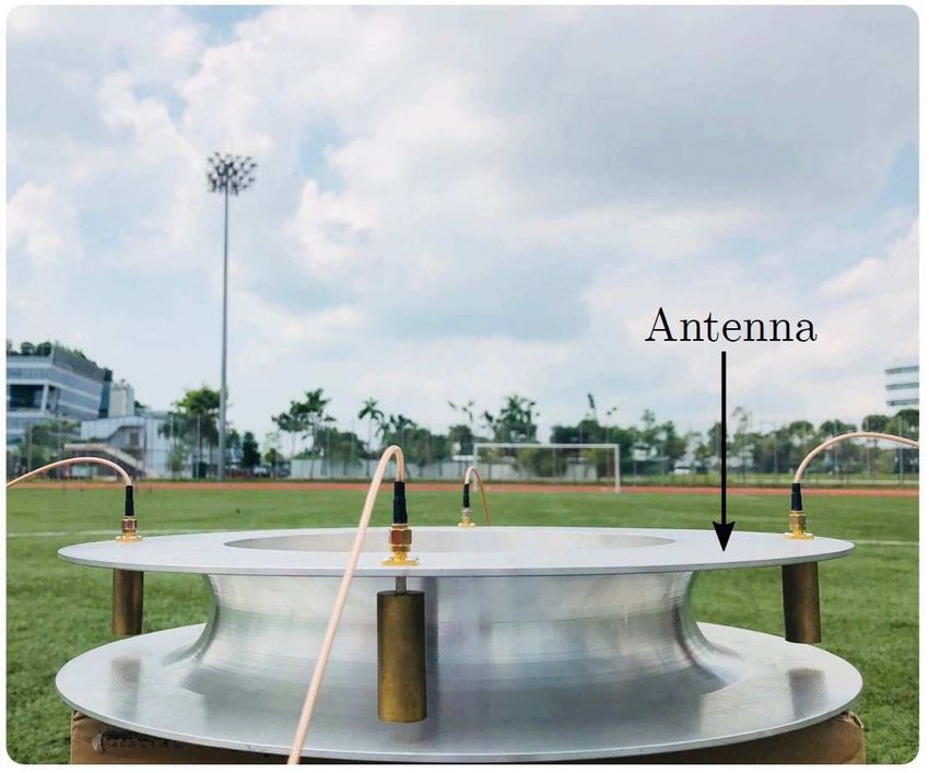
Our experimental setup comprises a SDR (USRP B210),
and a four element sector antenna, which is a variant of
the antenna implemented in [24]. We use only a single
RF receiving channel of the SDR. Therefore, the SDR is
connected to the antenna using a non-reflective Single-Pole-4-
Throw (SP4T) RF switch. DJI Phantom 3 is considered as the
target drone throughout the experiment. The drone downlink
channels occupy the bandwidth from 2.401 GHz to 2.481 GHz,
each has 10 MHz bandwidth OFDM signal. This OFDM signal
(a) Training Field (b) Direction Configuration
transmitted by the drone provides the main source to perform
the DF task.
Fig. 3. The Training Field and The Direction Configuration.
Fig. 3-(a) represents the environment that we used for
the training data collection. This is a large ground with an
open area. Also, there was negligible RF interference on the robust, and it outperforms the baseline method.
2.401 GHz - 2.481 GHz range. To simplify the experiment, Since our implementation does not use multiple RF channels
we virtually divided the area into eight octants, see Fig. 3- and any information about the antenna radiation pattern, it
(b). Each octant is considered as one direction during the is not desirable to compare our results with conventional
experiment. For example, the first octant is considered as 0 techniques. Therefore, we omit such simulation/experimental
degrees direction, while the second octant is considered as 45 results. Further interesting experimental evaluations and in-
degrees direction, and so on. Therefore, when the drone is sights will be presented in future extensions of this work.
flying, its direction is indicated by its corresponding octant.
In the trained network, L5 −th layer has eight neurons (we V. C ONCLUSION
have eight classes for the direction classification, or, Q = 8) This paper has proposed a novel DF method to be used
and L1 −th layer has four neurons (the antenna array has four in a drone surveillance system. The system comprises a
elements, or, N = 4). The hidden layers L2 , L3 , and L4 have single channel receiver and a directional antenna array. The
200, 12, and 12 neurons, respectively. These values have been receiver sequentially activates each antenna in the array, and
empirically decided during the training process. measures the received power values. The power measurements
After the training phase, the evaluation is done in a different corresponding to each switching cycle are fed to the pro-
environment. Now, the frequency spectrum (2.401 GHz - posed deep network. Then, it performs DF by exploiting the
2.481 GHz) suffers from WiFi and bluetooth interferences. sparsity property of the incoming drone signal, and the gain
To this end, two experiments have been carried out. First, we variation property of the directional antenna array. The paper
evaluated the proposed deep architecture, and its confusion has validated the proposed method experimentally. Also, it
matrix is given in the Table I. Next, we considered a baseline has been proven that a phase synchronization mechanism, an
method, where only a conventional DNN is implemented antenna gain calibration mechanism, and the analytical model
without the L2 layer (other layers have same number of nodes). of the antenna radiation pattern are not essential for this single
Its confusion matrix is given in the Table II. Note that the channel implementation. In future the scheme will be applied
confusion matries represent the percentage (%) values. It can to portable, SDR-based prototype design [9] and field test and
be observed that the proposed deep architecture is certainly experiment.R EFERENCES Proc. Instituto Tecnologico de Aeronautica (ITA), Sep. 2014.
[1] Y. Sun, H. Fu, S. Abeywickrama, L. Jayasinghe, C. Yuen, and J. Chen, [13] H. Fu, S. Abeywickrama, and C. Yuen, “A robust phase-ambiguity-
“Drone classification and localization using micro-doppler signature immune doa estimation scheme for antenna array,” To appear in IEEE
with low-frequency signal,” To appear in IEEE International Conference International Conference on Communication Systems, 2018.
on Communication Systems, 2018. [14] S. Maddio, M. Passafiume, A. Cidronali, and G. Manes, “A closed-form
[2] Q. Wu, Y. Zeng, and R. Zhang, “Joint trajectory and communication formula for RSSI-based doa estimation with switched beam antennas,”
design for multi-UAV enabled wireless networks,” IEEE Trans. Wireless in Proc. 2015 European Radar Conference, Sep. 2015.
Commun., vol. 17, no. 3, pp. 2109–2121, 2018. [15] R. Pöhlmann, S. Zhang, T. Jost, and A. Dammann, “Power-Based
[3] Q. Wu and R. Zhang, “Common throughput maximization in UAV- Direction-of-Arrival Estimation Using a Single Multi-Mode Antenna,”
enabled OFDMA systems with delay consideration,” To appear in IEEE ArXiv e-prints, Jun. 2017.
Trans. Commun., 2018. [16] S. Maddio, M. Passafiume, A. Cidronali, and G. Manes, “A scalable dis-
[4] Q. Wu, J. Xu, and R. Zhang, “Capacity characterization of UAV-enabled tributed positioning system augmenting wifi technology,” in Proc. IEEE
two-user broadcast channel,” To appear in IEEE J. Sel. Areas Commun., International Conference on Indoor Positioning and Indoor Navigation,
2018. Oct. 2013.
[5] Q. Wu, L. Liu, and R. Zhang, “Fundamental tradeoffs in communication [17] M. Abadi and A. Agarwal, “Tensorflow: Large-scale machine learning
and trajectory design for UAV-enabled wireless network,” Submitted to on heterogeneous distributed systems,” ArXiv e-prints, Mar. 2016.
IEEE Trans. Wireless Commun., 2018. [18] B. R. Jackson, S. Rajan, B. Liao, and S. Wang, “Direction of arrival
[6] B. Jansen, “Drone crash at white house reveals security risks.” [online] estimation using directive antennas in uniform circular arrays,” IEEE
https://www.usatoday.com/story/news/2015/01/26/, 2015. [Accessed on Trans. Antennas and Propagation, vol. 63, pp. 736–747, Feb. 2015.
26 November 2017]. [19] S. Kullback and R. Leibler, “On information and sufficiency,” The
[7] J. Serna, “Lufthansa jet and drone nearly collide near lax.” [online] Annals of Mathematical Statistics, vol. 22, pp. 79–86, Mar. 1951.
www.latimes.com/local/lanow/la-me-ln-drone-near-miss-lax-20160318, [20] C. Bishop, Pattern Recognition and Machine Learning. Springer-Verlag,
2016. [Accessed on 26 November 2017]. 2006.
[8] A. Morrow, “Couple accuses neighbor of stalking with drone.” [online] [21] K. Hara, D. Saito, and H. Shouno, “Analysis of function of rectified
https://www.suasnews.com/2014/12/, 2014. [Accessed on 26 November linear unit used in deep learning,” in Proc. IEEE International Joint
2017]. Conference on Neural Networks, Jul. 2015.
[9] H. Fu, S. Abeywickrama, L. Zhang, and C. Yuen, “Low complexity [22] L. Jayasinghe, N. Wijerathne, and C. Yuen, “A deep learning approach
portable passive drone surveillance via SDR-based signal processing,” for classification of cleanliness in restrooms,” To appear in Proc. IEEE
IEEE Commun. Mag., vol. 56, pp. 112–118, Apr. 2018. International Conference on Intelligent and Advanced Systems, Aug.
[10] R. Schmidt, “Multiple emitter location and signal parameter estimation,” 2018.
IEEE Trans. Antennas and Propagation, vol. 34, pp. 276–280, Mar. [23] L. Jayasinghe, T. Samarasinghe, C. Yuen, and S. S. Ge, “Temporal
1986. convolutional memory networks for remaining useful life estimation of
[11] R. Ray and T. Kailath, “ESPRIT-estimation of signal parameters via industrial machinery,” To appear in IEEE International Conference on
rotational invariance techniques,” IEEE Trans. Acoustics, Speech, Signal Industrial Technology, 2019.
Processing, vol. 37, pp. 984–995, Jul. 1989. [24] L. Yang, Z. Shen, W. Wu, and J. D. Zhang, “A four-element array of
[12] J. van der Merwe, J. Malan, F. Maasdorp, and W. D. Plessis, “Multi- wideband low-profile H-Plane horns,” IEEE Trans. Vehicular Technol-
channel software defined radio experimental evaluation and analysis,” in ogy, vol. 64, pp. 4356–4359, Sep. 2015.You can also read