Configuring IP and IP/RIP
←
→
Page content transcription
If your browser does not render page correctly, please read the page content below
Chapter 9
                                                              Configuring IP and IP/RIP

  This chapter describes how to configure the IP and IP/RIP protocols on the HP ProCurve 9304M, 9308M, and
  6308M-SX routing switches using the CLI and Web management interface.

  NOTE: IP routing and IP/RIP are supported only on the routing switches, not on the 6208M-SX switch.

  To display IP and RIP configuration information and statistics, see “Configuring IP and IP/RIP” on page 9-3.
  For complete syntax information for the CLI commands shown in this chapter, see “Command Line Interface
  Commands” on page B-1.

  NOTE: 9304M and 9308M routing switches that use Redundant Management modules can contain a maximum
  of 80000 IP routes by default. The 6308M-SX and chassis devices that use other management modules can
  contain a maximum of 10000 IP routes by default. If you need to increase the capacity of the IP route table for
  BGP4, see “Modifying System Parameter Default Settings” on page 8-69.

Overview of IP/RIP
   IP/RIP is a distance-vector protocol. IP/RIP routers transmit and receive RIP updates to and from neighboring
  routers. By default, the routing switches send RIP updates every 30 seconds. You can change the update
  interval and many other IP and IP/RIP parameters if needed.
  The routing switch can receive multiple paths to a destination. The software evaluates the paths, selects the best
  path, and saves the path in the IP route table as the route to the destination. Typically, the best path is the path
  with the fewest hops. A hop is another router through which packets must travel to reach the destination. If the
  routing switch receives a RIP update from another router that contains a path with fewer hops than the path stored
  in the route table, the routing switch replaces the older route with the newer one. The routing switch then includes
  the new path in the updates it sends to other RIP routers.
  Each entry in the IP/RIP routing table includes the destination address, the next hop address, and a metric. The
  metric is equal to the number of hops required to reach a destination.
  The IP/RIP protocol on the 9304M, 9308M, and 6308M-SX routing switches supports the following RIP types:
  •   Version 1
  •   V1 compatible with V2
  •   Version 2 (the default)

                                                                                                                   9-1
Advanced Configuration and Management Guide

      IP/RIP Features
      RIP includes a number of features that help stabilize its performance in rapidly changing network conditions.
      These features include hop count limits, hold downs, split horizons, and poison reverse updates.
      Hop Count Limit
      A maximum of 15 hops is supported by IP/RIP. Any destination that is greater than 15 hops away is considered
      unreachable. Although limiting to larger networks, the low maximum hop count prevents endless loops in the
      network.
      Hold Downs
      A hold-down instructs routers to delay (hold down) action update messages received from routes that may be
      inactive. The period of time is generally longer than the time required to update the entire network with a routing
      change. This safeguard prevents an inactive route from being reinstated.
      Split Horizons
      Split horizons prevent routing loops from being generated by adjacent routers. This feature is useful when a
      router’s path to a given router is through another router. Split horizons allow a routing broadcast to be modified so
      that routers with intermediate routers in their path to a destination router, are not seen as a path to the destination
      router by the intermediate router.

      Figure 9.1    Split horizon in action

      For example, in Figure 9.1, without split horizon operating, router A could see router B as a path to router X.
      However, if A were to route to B to reach router X, a loop would occur. A split horizon modifies a routing broadcast
      so that the intermediate router does not treat the source router as a path to the destination router. In Figure 9.1,
      the link with an "X" over it indicates a loop that is prevented by the split-horizon feature.
      Poison Reverse Updates
      Poison reverse updates are used to prevent larger loops within the network by setting the metric (cost) of
      neighboring routes to infinity. This will prevent two-hop loops.
      IP/RIP Default Route Learning and Advertising
      The 9304M, 9308M, and 6308M-SX routing switches can learn and advertise default IP/RIP routes. This feature
      can be enabled on a global or interface basis. By default, this feature is disabled.

      Priority for learning of IP/RIP routes is in the following order:
      1.   Static IP/RIP routes.
      2.   IP/RIP routes learned from RIP.
      3.   IP/RIP routes learned from OSPF.

9-2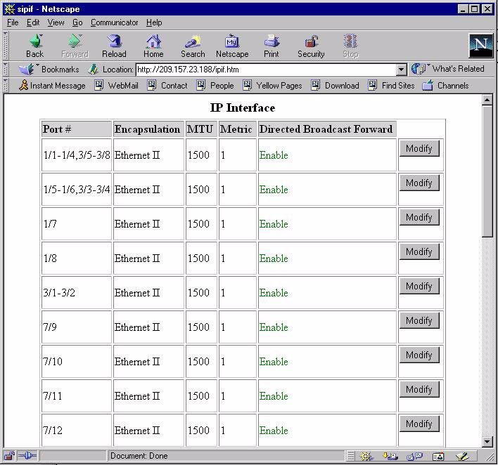
Configuring IP and IP/RIP

  ICMP Host Unreachable Message for Undeliverable ARPs
  If the routing switch receives an ARP request packet that it is unable to deliver to the final destination because of
  the ARP timeout and no ARP response is received (the routing switch knows of no route to the destination
  address), the routing switch sends an ICMP Host Unreachable message to the source.

Configuring IP and IP/RIP
  By default, the IP protocol is active on the 9304M, 9308M, and 6308M-SX routing switches at initial start-up, so
  there is no need to enable the protocol. However, you do need to assign IP addresses.
  Static routes, IP access policies (sometimes called "IP filters"), and the UDP helper feature are components of the
  IP protocol. Additionally, the protocol comes with system (global) and interface level parameters that you can
  modify to better suit the needs of the network.
  The following actions can be done at the IP and RIP levels of the CLI or from the IP and RIP configuration sheets
  of the Web management interface:
  1.   Enable IP/RIP.
  2.   Assign IP addresses to routing switch interfaces.
  3.   Modify global IP parameters (optional).
  4.   Modify interface IP parameters (optional).
  5.   Define static IP routes (optional).
  6.   Assign Static ARP and RARP entries (optional).
  7.   Define IP filters (optional).
  8.   Configure UDP helper (optional).
  9.   Define IP/RIP route filters (optional).
  10. Define IP/RIP route filter groups (optional).
  11. Modify the RIP global default parameters−metric value, update time parameters (optional).
  12. Configure redistribution filters, if non-RIP routes are to be imported into RIP.
  13. Modify or enable interface parameters—RIP type or poison reverse (optional).

  Dynamic IP/RIP Configuration
  This feature allows a routing switch to apply key IP/RIP configuration changes immediately without requiring a
  system reset. Here is a summary of those parameters:
  •    Enabling or disabling of RIP
  •    Adding a static route
  •    Enabling RARP or Proxy ARP
  •    Adding static ARP or RARP entries
  •    Setting the ARP cache aging value
  •    Enabling ICMP Router Discovery Protocol (IRDP)
  •    Adding a Relay BootP server address
  •    Setting RIP transmit intervals
  •    Assignment of RIP type—V1, V2 or V1/V2 compatible
  •    Activating RIP poison reverse

                                                                                                                    9-3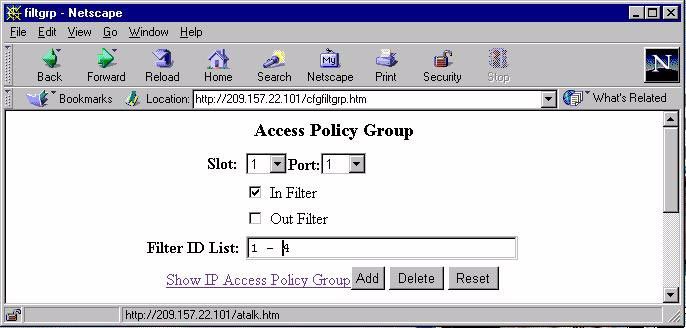
Advanced Configuration and Management Guide

      Enabling IP/RIP
      The IP/RIP protocol is disabled by default. It must be enabled on the routing switch, and the system must be reset
      before you can use the protocol.
      USING THE CLI
      To enable RIP on a routing switch, enter the following commands:
      HP9300(config)# router rip
      HP9300(config)# exit
      HP9300# write mem
      HP9300# reload
      syntax: router rip

      NOTE: In the above example, the system is reset to enable the IP/RIP protocol. HP recommends that you config-
      ure all elements of the protocol before you reset the system.

      USING THE WEB MANAGEMENT INTERFACE
      1.       Select the System link from the main menu.
      2.       Select the checkbox next to RIP.
      3.       Select the Save To Flash link from the main menu.
      4.       Select the Reload option from the main menu.

      Assigning IP Addresses
      Before attaching equipment to the routing switch, you must assign individual sub-net IP addresses and masks for
      each of the ports based on the desired and current network topology.
      By default, you can configure up to 24 IP interfaces on each port, virtual interface, and loopback interface. The
      9304M, 9308M, and 6308M-SX routing switches support both classical IP network masks (Class A, B, and C sub-
      net masks, and so on) and Classless Interdomain Routing (CIDR) network prefix masks.
      •        To enter a classical network mask, enter the mask in IP address format. For example, enter
               "209.157.22.99 255.255.255.0" for an IP address with a Class-C sub-net mask.
      •        To enter a prefix network mask, enter a forward slash ( / ) and the number of bits in the mask immediately
               after the IP address. For example, enter "209.157.22.99/24" for an IP address that has a network mask with
               24 significant bits (ones).
      By default, the CLI displays network masks in classical IP address format (example: 255.255.255.0). You can
      change the display to prefix format. See “Changing Network Mask Displays to Prefix Format” on page 9-10.
      USING THE CLI
      To assign an IP address for interface 1, enter the following commands:
      HP9300(config)# interface ethernet 1/1
      HP9300(config-if-1/1)# ip address 192.45.6.1 255.255.255.0
      Syntax: ip address   [secondary]
          or
      Syntax: ip address / [secondary]
      Use the secondary parameter if you have already configured an IP address within the same sub-net on the
      interface.

      NOTE: You also can enter the IP address and mask in the following manner:
      HP9300(config-if-1/1)# ip address 192.45.6.1/24

9-4
Configuring IP and IP/RIP

NOTE: Before exiting the Interface level of the CLI to configure IP interfaces on other routing switch ports, config-
ure the remaining parameters for the IP interface. For details on configuring IP interface parameters, see “Modify
IP and IP/RIP Interface Parameters (optional)” on page 9-26.

USING THE WEB MANAGEMENT INTERFACE
To assign an IP address:
1.   Select the IP Address link from the IP configuration sheet. The panel shown in Figure 9.2 will appear.

     NOTE: If at least one IP address is already defined on the system, then a summary panel appears first.
     Select the Add IP Address link.

2.   Select the port or slot/port combination that the address is to be assigned.
3.   Enter the IP address of the sub-net.
4.   Enter the sub-net mask.
5.   Select the Secondary box if the IP address being defined is not the first address assigned to this interface.
6.   Click the Add button to add the new IP address.

Figure 9.2    Assigning an IP address to an interface

Modifying Global IP and IP/RIP Parameters (optional)
Many IP/RIP parameters can be modified for the IP protocol on a global basis. Each of these parameters comes
with a default setting and does not need to be modified unless your network configuration requires a change.
You can perform the following parameter configuration tasks:
•    Modify the maximum number of hops for a BootP Relay server.
•    Modify the ARP aging period.
•    Modify the time-to-live (TTL) threshold.
•    Enable or disable RDP.
•    Enable or disable load sharing.
•    Enable or disable proxy ARP.
•    Enable or disable RARP.
•    Configure global static ARP or RARP entries.

                                                                                                                 9-5
Advanced Configuration and Management Guide

      •    Configure static IP routes.
      •    Configure IP access policies (IP forwarding filters).
      •    Enable or disable broadcast forwarding UDP Helper).
      •    Disable or re-enable directed broadcast forwarding.
      •    Change the display format for network masks to prefix format (CLI only).
      Figure 9.3 shows the IP configuration sheet in the Web management interface. You can change many of the IP
      parameters using this display.

      Figure 9.3    IP configuration sheet

      Modifying the Maximum Number of Hops to a BootP Relay Server
      The 9304M, 9308M, and 6308M-SX routing switches can support the relay of BootP requests to a BootP server
      outside of its network. You can modify the maximum number of hops that a request will traverse to a BootP
      server. The parameter value ranges from 1 – 15 hops. The default value is 4 hops.
      USING THE CLI
      To modify the maximum number of hops supported, enter the following command:
      HP9300(config)# bootp-relay-max-hops 10
      syntax: bootp-relay-max-hops
      USING THE WEB MANAGEMENT INTERFACE
      To modify the maximum number of hops supported:
      1.   Select the IP link from the main menu. The panel shown in Figure 9.3 will appear.
      2.   Enter a value from 1 – 15 into the BootP Relay Maximum Hop field.
      3.   Select the Apply button to assign the changes.

9-6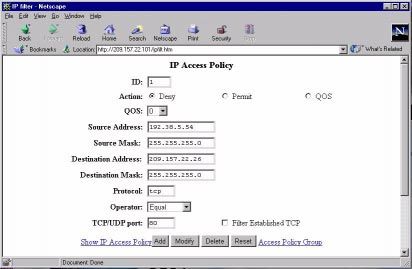
Configuring IP and IP/RIP

Modifying the ARP Aging Period
The ARP aging period defines how long an inactive ARP entry remains in the ARP cache before the routing switch
ages out the entry. The parameter value ranges from 0 – 240 minutes. If you enter 0, aging is disabled. The
default value is 10 minutes.
USING THE CLI
To modify the ARP aging parameter to 20 minutes, enter the following command:
HP9300(config)# ip arp-age 20
syntax: ip arp-age
USING THE WEB MANAGEMENT INTERFACE
1.   Select the IP link from the main menu. The panel shown in Figure 9.3 will appear.
2.   Enter a value from 0 – 240 into the ARP Age field.
3.   Select the Apply button to assign the changes.
Modifying the tTTL Threshold
This parameter defines how long a packet will remain alive on the network. The range is from 1 – 255 hops. The
default value for this parameter is 64 hops.
USING THE CLI
To modify the TTL threshold to 25, enter the following commands:
HP9300(config)# ip ttl 25
HP9300(config)# exit
syntax: ip ttl
USING THE WEB MANAGEMENT INTERFACE
1.   Select the IP link from the main menu. The panel shown in Figure 9.3 will appear.
2.   Enter a value from 1 – 255 into the TTL field.
3.   Select the Apply button to assign the changes.
Changing the Router ID
The OSPF and BGP4 protocols use router IDs to identify the routers that are running the protocols. A router ID is
a valid, unique IP address and sometimes, is an IP address configured on the router. The router ID cannot be an
IP address in use by another device. By default, the router ID is the lowest IP address configured on the routing
switch. However, you can set the router ID to any valid IP address.

NOTE: The routing switches use the same router ID for both OSPF and BGP4. If the routing switch is already
configured for OSPF, you may want to use the router ID that is already in use on the routing switch rather than set
a new one. To display the router ID, enter the show ip CLI command at any CLI level or select the IP link in the
Web management interface.

USING THE CLI
To set the router ID, enter a command such as the following:
HP9300(config)# ip router-id 209.157.22.26
Syntax: ip router-id
The  can be any valid, unique IP address.

NOTE: You can specify an IP address used for an interface on the routing switch, but do not specify an IP address
in use by another device.

                                                                                                                9-7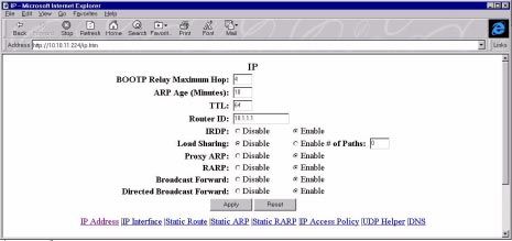
Advanced Configuration and Management Guide

      USING THE WEB MANAGEMENT INTERFACE
      1.   Select the IP link to display the IP configuration sheet, which is shown in Figure 9.3.
      2.   Edit the value in the Router ID field to any valid IP address not in use on another router.
      3.   Click the Apply button to assign the change.
      Enabling or Disabling IRDP
       IIRDP allows routers to dynamically learn about routes on other networks. The routing switch advertises its IP
      addresses to other routers on the network and answer queries from those routers. The default value for this
      feature is enabled.
      USING THE CLI
      To disable IRDP on a routing switch, enter the following command:
      HP9300(config)# no ip irdp
      To re-enable IRDP on a routing switch, enter the following command:
      HP9300(config)# ip irdp
      syntax: [no] ip irdp
      USING THE WEB MANAGEMENT INTERFACE
      1.   Select the IP link from the main menu. The panel shown in Figure 9.3 will appear.
      2.   Select IRDP.
      3.   Select the Apply button to assign the changes.
      Enable or Disable Suppression of Directed Broadcasts
      The H9304M, 9308M, and 6308M-SX routing switches allow directed IP broadcast forwarding by default, per
      section 5.3.5.2 in RFC 1812. However, if you want to suppress these directed broadcasts, you can do by entering
      the following command at the CONFIG level of the CLI:
      HP9300(config)# no ip directed-broadcast
      syntax: [no] ip directed-broadcast
      The software makes the forwarding decision based on the routing switch’s knowledge of the destination network
      prefix. Routers cannot determine that a message is unicast or directed broadcast apart from the destination
      network prefix. The decision to forward or not forward the message is by definition only possible in the last hop
      router.
      Directly attached network or sub-network broadcast forwarding can be suppressed on the routing switches. Thus,
      you have the option to suppress directed broadcasts on directly attached networks or sub-networks on a global or
      per interface level.
      To enable the suppression of directed broadcasts, enter the following command in the CONFIG mode:
      HP9300(config)# ip directed-broadcast
      Enable or Disable Load Sharing
      Load sharing allows traffic to be sent across multiple paths of equal cost to a destination, resulting in a faster
      transmission. This feature is available when using the OSPF routing protocol. This feature is by default disabled.

      NOTE: For information about configuring OSPF, see “Configuring OSPF” on page 10-1.

      USING THE CLI
      To enable load sharing for OSPF, enter the following command:
      HP9300(config)# ip load-sharing []
      syntax: [no] ip load-sharing []

9-8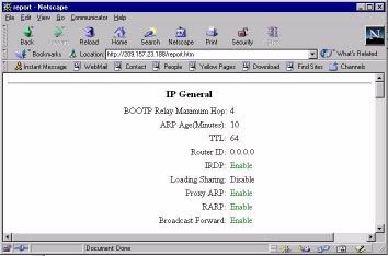
Configuring IP and IP/RIP

You can specify from 2 – 8 paths. The default is 4.
See “Enable Load Sharing” on page 10-21 for more information about this feature.
USING THE WEB MANAGEMENT INTERFACE
1.   Select the IP link from the main menu to display the panel shown in Figure 9.3.
2.   Enable the Load Sharing option.
3.   Select the Apply button to assign the changes.
Disabling or Enabling Proxy ARP
Proxy ARP enables or disables a routing switch as proxy for devices on its sub-nets. As proxy, the routing switch
responds to ARP requests from other devices on the network. By default, this feature is enabled on the routing
switch.
USING THE CLI
To disable the proxy ARP function on the routing switch, enter the following command:
HP9300(config)# no ip proxy-arp
To re-enable the proxy ARP function on the routing switch, enter the following command:
HP9300(config)# ip proxy-arp
syntax: [no] ip proxy-arp
USING THE WEB MANAGEMENT INTERFACE
1.   Select the IP link from the main menu to display the panel shown in Figure 9.3.
2.   Enable the Proxy ARP option.
3.   Select the Apply button to assign the changes.
Enable or Disable RARP
You can enable or disable Reverse Address Resolution Protocol (RARP) on the routing switch. RARP allows
retrieval of an IP address associated with a given MAC address. By default this feature is enabled.
USING THE CLI
To enable the RARP function on the routing switch, enter the following command:
HP9300(config)# ip rarp
syntax: [no] ip rarp
USING THE WEB MANAGEMENT INTERFACE
1.   Select the IP link from the main menu. The panel shown in Figure 9.3 will appear.
2.   Enable the RARP option.
3.   Select the Apply button to assign the changes.
Enabling or Disabling Broadcast Forward
Broadcast forward allows the routing switch to make UDP helper assignments. Broadcast forward is used in
conjunction with the UDP helper feature to define the type of application traffic (port number or socket) that is
being forwarded to the server. By default this feature is enabled.
Additional configuration is required to configure the UDP helper feature. For more details on configuring UDP
helper, see “Configuring UDP Helper (optional)” on page 9-32.

                                                                                                                9-9
Advanced Configuration and Management Guide
USING THE CLI
To enable the broadcast forwarding of snmp traps, enter the following command:
HP9300(config)# ip forward-protocol udp snmp-trap
Syntax: ip forward-protocol udp |
Possible values:
number echo snmp-trap
bootpc mobile-ip tacacs
bootps netbios-dgm talk
discard netbios-ns
dnsix ntp
tftp snmp
In addition, you can specify any UDP application by using the application’s UDP port number.
NOTE: By default, when an IP helper address is configured on an interface, UDP broadcast forwarding is enabled
for the following UDP packets: bootps, domain, tftp, time, netbios-dgm, netbios-ns, and tacacs.
USING THE WEB MANAGEMENT INTERFACE
1. Select the IP link from the main menu. The panel shown in Figure 9.3 will appear.
2. Enable the Broadcast Forward option.
3. Select the Apply button to assign the changes.
NOTE: To define the ports to be forwarded, select the UDP Helper link from the IP configuration sheet.
Changing Network Mask Displays to Prefix Format
By default, the CLI displays network masks in classical IP address format (example: 255.255.255.0). You can
change the displays to prefix format (example: /18) by entering the following command at the Privileged (Enable)
or CONFIG level of the CLI:
HP9300(config)# ip show-subnet-length
9-10Configuring IP and IP/RIP
Defining Static IP Routes
You can manually add static IP routes by entering a destination IP address and mask along with the IP address of
the next hop router. You also can assign the default router as the destination by entering 0.0.0.0 0.0.0.0.
The routing switches support up to 16 static routes by default. You can increase this support to up to 64 routes if
needed.
NOTE: In software release 05.0.00 and later, the software will replace a statically configured static default route
with a learned default route if the learned route’s administrative distance is lower than the statically configured
default route’s distance. However, the default administrative distance for static routes is changed to 1 in software
release 05.2.00, so only directly-connected routes are preferred over static routes when the default administrative
distances for the routes are used.
USING THE CLI
To enter static IP route 1 with a destination address of 192.0.0.0 255.0.0.0 and a next hop router IP address of
195.0.0.0 on interface 1/6, enter the following commands:
HP9300(config)# ip route 1 192.0.0.0 255.0.0.0 195.1.1.1
Syntax: ip route [] [distance ]
USING THE WEB MANAGEMENT INTERFACE
1. Select the Static Route option from the IP configuration sheet. The static route entry panel shown in Figure
9.4 will appear.
NOTE: If static routes already exist on the routing switch, then the static route summary panel appears
instead. In this case, select the Add Static Route link to reach the Static route entry panel.
2. Enter the IP address in the Network field.
3. Enter the IP mask.
4. Enter the address of the next hop router that provides access to that destination.
5. Enter a default metric for the route if a value other than the one configured at the interface level is desired.
The default metric is 1.
6. Enter the administrative distance for the static route. Each type of route on the routing switch has a different
default administrative distance. See “Changing Administrative Distances” on page 12-22.
7. Click the Add button to save the entry to the static route table.
Figure 9.4 Defining an IP static route
9-11Advanced Configuration and Management Guide
Assigning Static ARP and RARP Entries (optional)
You can assign up to 16,000 static ARP and RARP entries.
USING THE CLI
To assign a static ARP entry on a chassis system, enter a command such as the following:
HP9300(config)# arp 1 192.53.4.2 1245.7654.2348 e 1/2
Syntax: arp ethernet
USING THE WEB MANAGEMENT INTERFACE
1. Select Static ARP from the IP configuration sheet. The panel shown in Figure 9.5 will appear.
NOTE: If any static ARP entries are defined on the routing switch, the static ARP summary panel appears
first. In this case, select Add Static ARP.
2. Enter the IP address.
3. Enter the MAC address.
4. Select the port that the static ARP entry is to be assigned to from the pull down menu.
5. Click the Add button to save the entry to the static ARP table.
NOTE: You must be directly linked to an IP interface for which you are defining a static ARP.
Figure 9.5 Static ARP entry panel
USING THE CLI
To assign a static IP RARP entry for static routes on a routing switch, enter the a command such as the following:
HP9300(config)# rarp 1 1245.7654.2348 192.53.4.2
syntax: rarp . ethernet
9-12Configuring IP and IP/RIP
USING THE WEB MANAGEMENT INTERFACE
1. Select Static RARP from the IP configuration sheet. The panel shown in Figure 9.6 will appear.
NOTE: If any static RARP entries are defined on the routing switch, the static RARP summary panel appears
first. In this case, select Add Static RARP.
2. Enter the MAC address.
3. Enter the IP address.
4. Click the Add button to save the entry to the static RARP table.
Figure 9.6 Static RARP entry panel
Assigning IP and IP/RIP Filters
You can define IP and IP/RIP filters on a global basis and assign filters on an interface basis. You also can define
filters for redistributing routes among RIP and OSPF. This section describes how to perform the following filter
tasks:
• Define IP access policies (permit and deny filters).
• Assign IP access policies to specific ports.
• Define IP/RIP filters.
• Assign IP/RIP filter groups to specific ports.
• Define IP/RIP neighbor filters.
• Define IP/RIP redistribution filters.
The following sections describe how to configure these access policies and filters. For more information, see
“Policies and Filters” on page D-1.
9-13Advanced Configuration and Management Guide
Defining IP Access Policies
You can enhance network security by configuring IP access policies to explicitly permit or deny IP packets based
on IP protocol, IP source and destination, IP protocol port, and even TCP or UDP application port.
NOTE: The routing switch permits all IP packets by default. However, once you configure an IP access policy, the
routing switch denies all IP packets by default unless you explicitly permit them. Thus, if you want the routing
switch to permit all IP packets except the ones you filter out, you must configure the last IP access policy to permit
all IP packets. If a packet does not match other filters (and thus is not denied), the packet matches the last filter
and is permitted.
You can filter on the following IP protocols:
• ICMP
• IGMP
• IGRP
• OSPF
• TCP
• UDP
In addition, if you filter on TCP or UDP, you also can specify a particular application port (such as "HTTP" or "80")
or a logical expression consisting of an operator and port names or numbers. See the syntax descriptions below
for details.
USING THE CLI
EXAMPLE 1: To configure an IP access policy that globally accepts all FTP traffic without regard to network
orientation, use the wildcard value ‘any' in place of an IP address and enter the following command:
HP9300(config)# ip access-policy 1 permit any any tcp eq ftp
EXAMPLE 2: To configure an IP access policy that accepts only FTP traffic from a specific network, enter the
following command:
HP9300(config)# ip access-policy 1 permit 192.38.5.54 255.255.255.0 195.38.5.53
255.255.255.0 tcp eq ftp
Syntax: ip access-policy deny|permit |any |any
icmp|igmp|igrp|ospf|tcp|udp| [ [tcp/udp-port-num>]] [log]
ip access-policy-group in|out
NOTE: For backward compatibility, the routing switch also supports the ip filter and ip policy commands. The
parameters are the same as those for the ip access-policy command.
The parameter is the policy number.
The deny|permit parameter specifies the action the routing switch takes if a packet matches the policy.
• If you specify deny, the routing switch drops the packet.
• If you specify permit, the routing switch forwards the packet.
The |any |any parameters specify the source and destination IP
addresses. If you specify a particular IP address, you also need to specify the mask for that address. If you
specify any to apply the policy to all source or destination addresses, you do not need to specify any again for the
mask. Make sure you specify a separate address and mask or any for the source and destination address.
The icmp|igmp|igrp|ospf|tcp|udp| parameter specifies the IP protocol to which you are applying the
policy. If you specify tcp or udp, you also can use the optional and parameters
to fine-tune the policy to apply to specific TCP or UDP ports.
9-14Configuring IP and IP/RIP
The parameter applies only if you use the tcp or udp parameter above. Use the
parameter to specify the comparison condition for the specific TCP or UDP ports. For example, if you are
configuring QoS for HTTP, specify tcp eq http. You can enter one of the following operators:
• eq – The policy applies to the TCP or UDP port name or number you enter after eq.
• gt – The policy applies to TCP or UDP port numbers greater than the port number or the numeric equivalent
of the port name you enter after gt.
• lt – The policy applies to TCP or UDP port numbers that are less than the port number or the numeric
equivalent of the port name you enter after lt.
• neq – The policy applies to all TCP or UDP port numbers except the port number or port name you enter after
lt.
• range – The policy applies to all TCP or UDP port numbers that are between the first TCP or UDP port name
or number and the second one you enter following the range parameter. The range includes the port names
or numbers you enter. For example, to apply the policy to all ports between and including 23 (Telnet) and 53
(DNS), enter the following: range 23 53. The first port number in the range must be lower than the last
number in the range.
• established – This operator applies only to TCP packets. If you use this operator, the policy applies to TCP
packets that have the ACK (Acknowledgment) or RST (Reset) bits set on (set to "1") in the Control Bits field of
the TCP packet header. Thus, the policy applies only to established TCP sessions, not to new sessions. See
Section 3.1, "Header Format", in RFC 793 for information about this field.
The log parameter applies only to deny policies. This parameter generates a Syslog entry for packets that are
denied by the policy. See “show logging” on page B-242.
9-15Advanced Configuration and Management Guide
Figure 9.7 and Figure 9.8 show the CLI syntax for configuring an IP access policy.
ip access-policy deny|permit |any |any
icmp
igmp
igrp
ospf
tcp eq
bgp | dns |
gt
ftp | http |
lt
imap4 | ldap |
neq
nntp | pop2 |
pop3 | smtp |
ssl | telnet |
bgp | dns | bgp | dns |
range
ftp | http | ftp | http |
imap4 | ldap | imap4 | ldap |
nntp | pop2 | nntp | pop2 |
pop3 | smtp | pop3 | smtp |
ssl | telnet | ssl | telnet |
eq
bgp | dns |
gt
established ftp | http |
lt
imap4 | ldap |
neq
nntp | pop2 |
pop3 | smtp |
ssl | telnet |
bgp | dns | bgp | dns |
range
ftp | http | ftp | http |
imap4 | ldap | imap4 | ldap |
nntp | pop2 | nntp | pop2 |
pop3 | smtp | pop3 | smtp |
ssl | telnet | ssl | telnet |
udp see the next page...
Figure 9.7 IP access policy syntax for an IP access policy (1 of 2)
9-16Configuring IP and IP/RIP
continued from previous page
udp eq
gt bootpc | bootps |
lt dns | tftp |
neq ntp | radius |
radius-old | rip |
snmp | snmp-trap |
bootpc | bootps | bootpc | bootps |
range
dns | tftp | dns | tftp |
ntp | radius | ntp | radius |
radius-old | rip | radius-old | rip |
snmp | snmp-trap | snmp | snmp-trap |
in
ip access-policy-group
out
Figure 9.8 IP access policy syntax for an IP access policy (2 of 2)
USING THE WEB MANAGEMENT INTERFACE
To add an IP access policy:
1. Select the IP Access Policy link from the IP configuration sheet. The panel shown in Figure 9.9 will appear.
NOTE: If IP filters are already defined on the routing switch, then the IP filter summary panel is displayed. In
this case, select the Add IP Filter link.
2. Enter an ID for the access policy.
3. Select Permit, Deny, or QoS.
NOTE: If you select QoS, you are configuring a Layer 4 Quality of Service (Qos) policy. See “Applying Layer
4 QoS Priority on the HP 9304M, 9308M, or 6308M-SX Routing Switch” on page 8-63.
4. Enter the source address and mask for the policy.
NOTE: You can specify the wildcard value "any" in the source and destination IP address and mask fields to
allow all traffic. Entering 0.0.0.0 represents "any". Likewise, to allow all protocols to be accepted by a filter,
you can enter a single zero (0) in the protocol field.
5. Enter the destination address and mask for the policy.
9-17Advanced Configuration and Management Guide
6. If you want to filter on a specific IP protocol, select the protocol from the Protocol field’s pulldown menu. For
example, to filter on TCP packets, select TCP. You can enter the protocol number or select one of the
following:
• ICMP
• IGMP
• IGRP
• OSPF
• TCP
• UDP
7. If you selected TCP or UDP, you can select a comparison operator. Select the operator from the Operator
field’s pulldown menu. You can select one of the following:
• Greater – The policy applies to TCP or UDP port numbers greater than the port number or the numeric
equivalent of the port name you specify.
• Equal – The policy applies to the TCP or UDP port name or number you specify.
• Less – The policy applies to TCP or UDP port numbers that are less than the port number or the numeric
equivalent of the port name you specify.
• Not Equal – The policy applies to all TCP or UDP port numbers except the port number or port name you
specify.
• Established (applies only to TCP) – This operator applies only to TCP packets. If you use this operator,
the policy applies to TCP packets that have the ACK (Acknowledgment) or RST (Reset) bits set on (set
to "1") in the Control Bits field of the TCP packet header. Thus, the policy applies only to established
TCP sessions, not to new sessions. See Section 3.1, "Header Format", in RFC 793 for information about
this field.
• Range – The policy applies to all TCP or UDP port numbers that are between the first TCP or UDP port
name or number and the second one you specify. The range includes the port names or numbers you
enter. For example, to apply the policy to all ports between and including 23 (Telnet) and 53 (DNS),
specify the following: "23 53". The first port number in the range must be lower than the last number in
the range.
8. If you selected a comparison operator, enter the port number in the TCP/UDP port field. For example, if you
selected TCP and Equal and you want to filter on HTTP traffic, enter the value 80 (the well-known port
number for HTTP).
NOTE: You must enter the port’s number instead of the well-known name.
9. Click the Add button to assign the IP access policy.
9-18Configuring IP and IP/RIP
Modify or Delete an IP Access Policy
1. Select IP Access Policy from the IP configuration sheet.
2. Click either the Modify or Delete button to the right of the IP policy you want to change or delete. If you click
Modify, an entry panel for that interface appears. Make the desired changes and click Add to save the
changes.
Figure 9.9 IP Access Policy entry panel
Applying IP Access Policies to Ports
Once you define an IP access policy, you can apply it to the inbound or outbound traffic on a port.
USING THE CLI
To assign IP access policies 2, 3, and 5 to port 1 on module 2 of a chassis, enter the following commands:
HP9300(config)# interface e 2/1
HP9300(config-if-2/1)# ip access-policy-group in 2 3 5
syntax: ip access-policy-group in|out
You also can specify policy ranges. For example, to apply policies 1 – 3, policy 9, and policies 11 – 25 to port 2/4’s
outbound policy group, enter the following command:
HP9300(config)# int ethernet 2/4
HP9300(config-if-2/4)# ip access-policy-group out 1 to 3 9 11 to 25
NOTE: For backward compatibility, the routing switch also supports the ip filter-group and ip policy-group com-
mands. The parameters are the same as those for the ip access-policy-group command.
9-19Advanced Configuration and Management Guide
USING THE WEB MANAGEMENT INTERFACE
To assign IP filters 1, 2, and 5 to port 1 on module 2 of a chassis:
1. Select the Access Policy Group link from the IP filter configuration panel, shown in Figure 9.10.
NOTE: If at least one IP access policy group is already defined on the routing switch, then the IP access pol-
icy group summary panel is displayed first. In this case, select the Add IP Access Policy Group link.
2. Select the port or slot/port to which you are assigning the access policies.
3. Select either or both the In and Out options.
• Selecting In applies the access policies to all incoming traffic on the port.
• Selecting Out applies the access policies to all outgoing traffic on the port.
• Selecting both options applies the access policies to both incoming and outgoing traffic.
4. Enter the access policy IDs in the Filter ID List field. To enter a range, enter the first policy number in the
range, a space, a dash, another space, and then the second policy number. For example, enter “1 – 4” to
specify the range 1 – 4.
NOTE: When specifying a range, you must use spaces on either side of the dash.
Figure 9.10 Assigning IP filters
9-20Configuring IP and IP/RIP
Defining IP/RIP Route Filters
To define an IP/RIP filter, RIP must be enabled on the routing switch. A filter controls the routes that are stored in
the IP routing table for inbound routes. For outbound routes, the filter defines the routes that are advertised
through a given interface. You can define up to 64 route filters for a routing switch.
NOTE: A route is defined by its IP address and IP mask.
USING THE CLI
To enable RIP on the routing switch and then define IP/RIP filters, enter the following commands:
HP9300(config)# router rip
HP9300(config-rip-router)# filter 1 permit 192.53.4.1 255.255.255.0
HP9300(config-rip-router)# filter 2 permit 192.53.5.1 255.255.255.0
HP9300(config-rip-router)# filter 3 permit 192.53.6.1 255.255.255.0
HP9300(config-rip-router)# filter 4 deny 192.53.7.1 255.255.255.0
syntax: filter
NOTE: Instead of specifying a specific route, you can specify all routes versus a specific sub-net by using the
value any.
USING THE WEB MANAGEMENT INTERFACE
To define a RIP route filter:
1. Select RIP Route Filter from the RIP configuration sheet to display the entry panel shown in Figure 9.11.
NOTE: If RIP route filters are already configured, a summary panel is displayed instead. In this case, select
the Add RIP Route Filter link to reach the entry panel.
2. Enter the filter ID.
3. Select either Permit or Deny as the action.
4. Enter an IP address and mask or the wildcard value, 0.0.0.0, to allow all routes.
5. Click the Add button to save the filter.
To modify or delete a RIP route filter:
1. Select RIP Route Filter from the RIP configuration sheet to display a summary panel of all defined RIP route
filters.
2. Click the Modify or Delete button next to the filter you want to change or delete. If the click Modify, enter the
changes to either or both of the Action or IP Address fields and then click the Modify button to apply the
changes. If you click Delete, the filter is removed immediately.
9-21Advanced Configuration and Management Guide
Figure 9.11 IP/RIP filter entry panel
Applying IP/RIP Route Filters to Ports
Once you define RIP route filters, you can assign them to individual ports. You also can specify whether the filters
apply to advertisements sent by the routing switch or to updates received by the routing switch. Out filters apply to
advertisements sent by the routing switch. In filters apply to updates received by the routing switch.
USING THE CLI
To assign route filters 2, 3, and 4 to all incoming routes on interface 2 of module 1, enter the following commands:
HP9300(config)# interface e 1/2
HP9300(config-if-1/2)# ip rip filter-group in 2 3 4
syntax: ip rip filter-group in|out
NOTE: If you specify out in the above example, filters 2, 3, and 4 are applied to all RIP routes being advertised.
You also can assign filter groups on a global basis.
USING THE WEB MANAGEMENT INTERFACE
1. Select the Filter Group link from the RIP filter configuration panel. The panel shown in Figure 9.12 will
appear.
2. Select the port or slot/port to which the filter(s) will be assigned.
3. Select either or both of the In Filter and Out Filter options.
• Selecting the In Filter option applies the filters to incoming traffic only.
• Selecting the Out Filter option applies the filters to outgoing traffic only.
• Selecting both options applies the filters to both incoming and outgoing traffic.
4. Enter the filters to be applied to the interface in the Filter ID List field.
5. Click the Add button to assign the changes.
9-22Configuring IP and IP/RIP
Figure 9.12 Assigning IP/RIP filters to an interface
Defining IP/RIP Neighbor Filters
By default, the routing switch learns RIP routes from all its RIP neighbors. Neighbor filters allow you to specify the
neighbor routers from which the routing switch can receive RIP routes. You can define up to 64 neighbor filters.
Neighbor filters apply globally to all ports.
USING THE CLI
To configure a routing switch so that no RIP routes are learned from neighbor routers, enter the following
command:
HP9300(config-rip-router)# neighbor 1 deny any
syntax: neighbor permit|deny |any
USING THE WEB MANAGEMENT INTERFACE
To define a RIP neighbor filter:
1. Select RIP Neighbor Filter from the RIP configuration sheet. The panel shown in Figure 9.13 will appear.
2. Enter the filter ID.
3. Select either the Permit or Deny action.
4. Enter the source IP address that will be filtered or 0.0.0.0 to filter on all neighboring routers.
5. Click the Add button to assign the filter.
To modify or delete a RIP neighbor filter:
1. Select RIP Neighbor Filter from the RIP configuration sheet. A summary panel of all defined RIP neighbor
filters will appear.
2. Click the Modify or Delete button next to the filter that is to be changed or deleted. If you click Modify, enter
the changes to the Action or IP Address fields and then click the Modify button apply the changes. If you click
Delete, the filter is removed immediately.
9-23Advanced Configuration and Management Guide
Figure 9.13 RIP neighbor filter entry panel
Defining Redistribution Filters
IP/RIP redistribution filters control redistribution of routes from other protocols into RIP. A routing switch running
RIP can redistribute static routes, OSPF routes, and BGP4 routes (if BGP4 is supported on the device) into RIP.
Optionally, you can specify a metric that the route must match or you can set the metric on redistributed routes.
By setting the metric, you can cause the routing switch to prefer IP/RIP routes or redistributed routes to the
specified network.
USING THE CLI
EXAMPLE 1: To deny redistribution on all incoming routes received from the 207.92.0.0 network (by interface),
enter the following commands:
HP9300(config)# router rip
HP9300(config-rip-router)# deny redis 2 all 207.92.0.0 255.255.0.0
EXAMPLE 2: To deny redistribution on OSPF routes only, enter the following command:
HP9300(config-rip-router)# deny redis 3 ospf 207.92.0.0 255.255.0.0
EXAMPLE 3: To deny redistribution by metric, enter the following command:
HP9300(config-rip-router)# deny redis 3 ospf 207.92.0.0 255.255.0.0 match-metric 10
Syntax: permit|deny redistribute all|bgp|ospf|static
[match-metric|set-metric ]
The all parameter applies redistribution to all route types.
The bgp parameter applies redistribution to BGP4 routes only.
The ospf parameter applies redistribution to OSPF routes only.
The static parameter applies redistribution to the static route only.
The parameters apply redistribution to the specified network and sub-net address.
The match-metric parameter applies redistribution to those routes with a specific metric value; possible
values are from 1 – 15.
The set-metric parameter sets the RIP metric value that will be applied to those routes imported into RIP.
9-24Configuring IP and IP/RIP
USING THE WEB MANAGEMENT INTERFACE
1. Select the Redistribution Filter link from the RIP configuration sheet. The panel shown in Figure 9.14 will
appear.
2. Enter an IP address and mask to filter on a specific network. You can use zeros (0.0.0.0) instead of a specific
interface to allow all IP addresses or mask ranges.
3. Enter the filter ID.
4. Select either Permit or Deny as the action.
5. Select the types of routes you want to filter on—All, Static, OSPF, or BGP4.
6. Enable the Match Metric parameter to limit the import of routes to only those that match the metric specified in
the Match Metric field.
7. Enable the Set Metric parameter to define and assign a specific metric to an imported route. If enabled, the
specified value overrides the default metric defined on the RIP configuration sheet.
8. Click the Add button to assign the redistribution filter.
Figure 9.14 IP/RIP redistribution filter entry panel
9-25Advanced Configuration and Management Guide
Modify IP and IP/RIP Interface Parameters (optional)
IP and IP/RIP come with default settings for their interface parameters. You do not need to modify any of these
parameters unless your network configuration requires a parameter change. You can configure the following
interface parameters:
• IP interface parameters:
• Encapsulation format
• Maximum transmission unit (MTU)
• Metric
• IP address used for stamping BootP/DHCP requests
• RIP interface parameters:
• RIP routing state on individual routing switch ports
• RIP Version—version 1, version 2, or version 2 with version 1 compatibility
• Poison reverse state
• Filter groups
Modifying IP Interface Parameters
Use the procedures in this section to modify the following parameters:
• Encapsulation format
• Maximum transmission unit (MTU)
• Metric
• IP address used for stamping BootP/DHCP requests
Modifying Encapsulation Format
The encapsulation format parameter allows you to select the encapsulation format to be used on a port for MAC
address encapsulation. This can vary by port. The options are Ethernet II or SNAP. The default format is
Ethernet II.
USING THE CLI
To change the encapsulation type on interface 1/5 to Ethernet SNAP, enter the following commands:
HP9300(config)# int e 1/5
HP9300(config-if-1/5)#ip encapsulation ethernet_snap
syntax: ip encapsulation
USING THE WEB MANAGEMENT INTERFACE
1. Select the IP Interface link from the IP configuration sheet. The panel shown in Figure 9.15 will appear.
2. Select the port (and slot, if applicable).
3. Select the encapsulation type from the pulldown menu.
4. Select the Apply button to assign the changes.
9-26Configuring IP and IP/RIP
Modifying the Size of the Maximum Transmission Unit (MTU)
The MTU field defines the maximum packet size to be accepted on a given port. The possible size for Ethernet II
packets is 572 – 1500 bytes. Ethernet SNAP packets can be from 572 – 1492 bytes. The default value for
Ethernet II packets is 1500. The default for SNAP packets is 1492.
USING THE CLI
To change the MTU for interface 1/5 to 1000, enter the following commands:
HP9300(config)# int e 1/5
HP9300(config-if-1/5)#ip mtu 1000
syntax: ip mtu (Ethernet SNAP); ip mtu (Ethernet II)
USING THE WEB MANAGEMENT INTERFACE
1. Select the IP Interface link from the IP configuration sheet to display the panel shown in Figure 9.15.
NOTE: If at least one IP interface is defined on the routing switch, then a summary panel will appear first. In
this case, select the Configure IP Interface link to reach the IP interface panel shown in Figure 9.15.
2. Enter an MTU value from 572 – 1500 if the interface is operating with Ethernet SNAP encapsulation. If the
interface is operating with Ethernet II, enter a value from 572 – 1492.
3. Select the Apply button to assign the changes.
Figure 9.15 IP interface configuration panel
Modifying the Metric
Metric defines the cost that will be applied to all IP routes on an interface. A metric cost from 1 – 16 can be
assigned. The default metric cost is 1.
USING THE CLI
To assign a route cost (metric) of 15 to interface 1/6:
HP9300(config)# int e 1/6
HP9300(config-if-1/6)# ip metric 15
syntax: ip metric
9-27Advanced Configuration and Management Guide
USING THE WEB MANAGEMENT INTERFACE
1. Select the IP Interface link from the main menu. The panel shown in Figure 9.15 will appear.
2. Enter a value from 1 – 16 for the metric.
NOTE: IP/RIP considers interfaces with a metric of 16 to be unreachable. Use this metric only if you do not
want the interface to be used.
3. Select the Apply button to assign the changes.
Modifying the IP Address Used for Stamping BootP/DHCP Requests
The routing switch assists BootP/DHCP requests by stamping such requests with the IP address of the gateway
that leads to the BootP/DHCP server. By default, the lowest numbered IP address on an interface is used as the
address for stamping the requests. To change the address, use one of the following methods.
USING THE CLI
To change the IP address used for stamping BootP/DHCP requests on interface 1/1, enter the following
commands:
HP9300(config)# int e 1/1
HP9300(config-if-1/1)# ip bootp-gateway 109.157.22.26
Syntax: ip bootp-gateway
USING THE WEB MANAGEMENT INTERFACE
You cannot change the IP address used for stamping BootP/DHCP requests using the Web management
interface.
IP/RIP Interface Parameters
Use the procedures in this section to modify the following parameters:
• RIP routing on individual routing switch ports
• RIP Version—version 1, version 2, or version 2 with version 1 compatibility
• Poison reverse
• Filter groups
NOTE: You also can define IP access policies, assign static IP routes and define static ARP and RARP entries for
interfaces. For more details on these features, see the specific sections on their configuration within this chapter.
Enabling IP/RIP Routing on Interfaces and Modify Parameters (optional)
As autonomous systems, the 9304M, 9308M, and 6308M-SX routing switches can support multiple protocols on
the same device. You can enable RIP on individual ports by selecting that port from the pulldown menu, assigning
a version type, then either enabling or disabling the parameter poison reverse.
USING THE CLI
To enable RIP on an interface, define the type of RIP route and enable poison reverse for interface 1/1, enter the
following commands:
HP9300(config)# int e1/1
HP9300(config-if-1/1)# ip rip v1-only
HP9300(config-if-1/1)# ip rip poison-reverse
HP9300(config-if-1/1)# end
9-28Configuring IP and IP/RIP
HP9300# write memory
HP9300# reload
syntax: ip rip ; syntax: ip rip poison-reverse
USING THE WEB MANAGEMENT INTERFACE
To enable RIP routing on individual interfaces:
1. Select RIP Interface from the RIP configuration sheet. The panel shown in Figure 9.16 will appear.
NOTE: If RIP is already defined on some interfaces, an interface configuration summary panel will appear. In
this case, select Configure RIP Interface to add an interface.
2. Select the port or slot/port to be configured from the pulldown menu.
3. Assign the RIP type version from the pull down menu. Options are version 1, version 2, v1 compatible v2 or
disabled. The default state is version 2.
4. Enable poison reverse, a loop prevention feature, if desired.
5. Select Apply to assign the changes.
NOTE: To assign the configured interface parameters to all other RIP interfaces on the routing switch, select the
Apply All Port button.
Figure 9.16 RIP interface display and entry panel
Modify Global IP/RIP Parameters
The IP/RIP protocol has some global parameters, which have default settings. You do not need to modify these
parameters unless your network configuration requires a parameter change.
The following RIP parameters are modified at the RIP router level when using the CLI and at the RIP configuration
sheet when using the Web management interface.
• Update time
• Enable or disable of redistribution
• Global default metric used for redistribution
• Enable IP/RIP Default Route Learning and Advertising
9-29Advanced Configuration and Management Guide
Modifying Update Time Value
The update time sets the time interval between the transmission of regular RIP response packets. Possible
values are 1 – 1000 seconds. The default value is 30 seconds.
USING THE CLI
To modify the interval at which RIP response packets are transmitted to 120 seconds, enter the following
commands:
HP9300(config)# router rip
HP9300(config-rip-router)# update 120
syntax: update-time
USING THE WEB MANAGEMENT INTERFACE
1. Select the RIP link from the main menu. The panel shown in Figure 9.17 will appear.
2. Enter a value from 1 – 1000 in the Update Time field.
3. Select the Apply button to assign the changes.
Figure 9.17 RIP configuration sheet
Enabling or Disabling Redistribution
When RIP is enabled, it imports external routes (OSPF routes, static routes, or BGP4 routes) into the RIP domain.
Redistribution is disabled by default.
USING THE CLI
To enable redistribution for RIP, the user would enter the following:
HP9300(config)# router rip
HP9300(config-rip-router)# redistribution
syntax: redistribution
USING THE WEB MANAGEMENT INTERFACE
1. Select the RIP link from the main menu to display the panel shown in Figure 9.17.
2. Enable redistribution.
3. Select the Apply button to assign the changes.
9-30Configuring IP and IP/RIP
Modifying the Redistribution Global Default Metric
The RIP redistribution metric allows you to define the global default metric (cost) assigned to all external routes
imported into RIP for redistribution. Possible values are 1 – 15. The default value is 1.
USING THE CLI
To assign a global metric of 10 as the default cost, enter the following commands:
HP9300(config)# router rip
HP9300(config-rip-router)# default 10
syntax: default-metric
USING THE WEB MANAGEMENT INTERFACE
1. Select the RIP link from the main menu. The panel shown in Figure 9.17 will appear.
2. Enter a value from 1 – 15 in the Redistribution Default Metric field.
3. Select the Apply button to assign the changes.
Modifying the Default Administrative Distance
The HP9304M, 9308M, and 6308M-SX routing switches can learn about networks from various protocols,
including Border Gateway Protocol version 4 (BGP4), IP/RIP, and OSPF. Consequently, the routes to a network
may differ depending on the protocol from which the routes were learned. The default administrative distance for
IP/RIP routes is 120. See “Changing Administrative Distances” on page 12-22 for a list of the default distances
for all route sources.
To select one route over another based on the source of the route information, the routing switch can use the
administrative distances assigned to the sources. You can bias the routing switch’s decision by changing the
default administrative distance for IP/RIP routes.
USING THE CLI
To change the administrative distance for IP/RIP routes to 140, enter the following commands:
HP9300(config)# router rip
HP9300(config-rip-router)# distance 140
syntax: distance
USING THE WEB MANAGEMENT INTERFACE
1. Select the RIP link from the main menu. The panel shown in Figure 9.17 will appear.
2. Edit the value in the Distance field.
3. Select the Apply button to assign the changes.
Enabling IP/RIP Default Route Learning and Advertising
You can enable learning and advertising of IP/RIP routes on a global or interface basis.
USING THE CLI
To enable learning of default IP/RIP routes on a global basis, enter the following commands:
HP9300(config)# router rip
HP9300(config-rip-router)# learn-default
To enable learning of default IP/RIP routes on an interface basis, enter the following commands:
HP9300(config)# int e1
HP9300(config-if-1)# ip rip learn-default
syntax: learn-default
9-31Advanced Configuration and Management Guide
USING THE WEB MANAGEMENT INTERFACE
To enable learning of default IP/RIP routes:
1. Select the RIP interface link from the RIP configuration sheet. A summary panel of all RIP interfaces will
appear.
NOTE: If RIP is already defined on some interfaces, an interface configuration summary panel will appear. In
this case, select Configure RIP Interface. Select the Modify button next to the interface upon which learning
of default routes is to be enabled. The RIP interface entry panel will appear.
2. Enable learn default.
3. Select the Apply button to assign the changes.
NOTE: To globally enable learning of default routes across all interfaces, select the Apply To All Ports button
instead of the Apply button.
Configuring UDP Helper (optional)
The 9304M, 9308M, and 6308M-SX routing switches support relay of UDP/DHCP packets to their destinations for
a specific application such as bootps, domain, tftp, and so on for cases where the destination server is not on the
local LAN segment.
The following port sockets names are supported for the UDP helper feature:
number echo snmp
bootpc mobile-ip snmp-trap
bootps netbios-dgm tacacs
discard netbios-ns talk
dnsix ntp tftp
NOTE: You also can specify any UDP application by its number.
NOTE: By default, when an IP helper address is configured on an interface, UDP broadcast forwarding is enabled
for the following UDP packets: bootps, domain, tftp, time, netbios-dgm, netbios-ns, and tacacs.
USING THE CLI
To configure the UDP/DHCP helper feature on interface 2 on chassis module 1, enter the following commands:
HP9300(config)# interface e 1/2
HP9300(config-if-1/2)# ip helper-address 1 207.95.7.6
syntax: ip helper-address
USING THE WEB MANAGEMENT INTERFACE
To configure the UDP/DHCP helper feature on an interface:
1. Select the UDP helper option on the IP configuration sheet to display the panel shown in Figure 9.18.
2. Select the port or slot/port to which the UDP helper packets will be forwarded from the pulldown menu(s).
3. Enter the IP address of the remote server for which the routing switch will be relaying the packets.
4. Select the Add button to apply the changes. You are now ready to assign applications to be forwarded,
highlighted in the next section.
9-32You can also read