XDirect Serial-to-Ethernet Device Server User Guide - Lantronix
←
→
Page content transcription
If your browser does not render page correctly, please read the page content below
xDirect
Serial-to-Ethernet Device Server
                     User Guide

                        Part Number 900-653-R
                        Revision C March 2020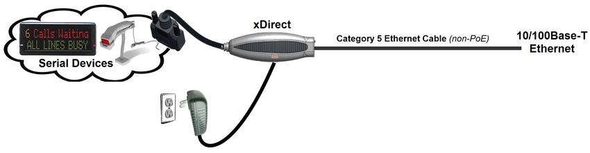
Copyright & Trademark
       © 2020 Lantronix, Inc. All rights reserved. No part of the contents of this book may be transmitted
       or reproduced in any form or by any means without the written permission of Lantronix.
       Lantronix is a registered trademark, and xDirect and DeviceInstaller are a trademarks of Lantronix,
       Inc.
       Patented: http://patents.lantronix.com; additional patents pending.
       Windows and Internet Explorer are registered trademarks of Microsoft Corporation. Mozilla and
       Firefox are registered trademarks of the Mozilla Foundation. Chrome is a trademark of Google.
       Tera Term is a registered trademark of Vector, Inc. All other trademarks and trade names are the
       property of their respective holders.

Warranty
       For details on the Lantronix warranty policy, please go to our web site at
       www.lantronix.com/support/warranty.

Contacts
       Lantronix, Inc.

       7535 Irvine Center Drive
       Suite 100
       Irvine, CA 92618, USA
       Toll Free:    800-526-8766
       Phone:        949-453-3990
       Fax:          949-453-3995
       Technical Support Online: www.lantronix.com/support
       Sales Offices
       For a current list of our domestic and international sales offices, go to the Lantronix web site at
       www.lantronix.com/about/contact.

Disclaimer
       The information in this guide may change without notice. The manufacturer assumes no
       responsibility for any errors that may appear in this guide.

Revision History
        Date                   Rev.     Comments
        September 2012         A        Initial document for firmware version 6.9.0.0.
        December 2017          B        Updated enhanced password information.
        March 2020             C        Updated for firmware version 7.0.0.1. Updated to include new default
                                        credentials and security information.

xDirect Serial-to-Ethernet Device Server User Guide                                                            2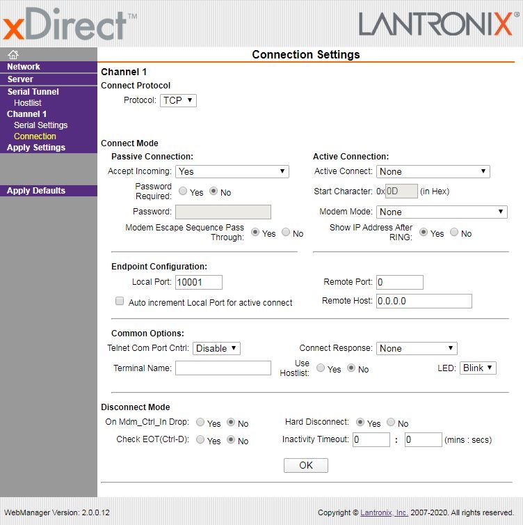
Table of Contents
           Copyright & Trademark ______________________________________________________ 2
           Warranty _________________________________________________________________ 2
           Contacts _________________________________________________________________ 2
           Disclaimer ________________________________________________________________ 2
           Revision History ___________________________________________________________2
           Table of Contents __________________________________________________________ 3
           List of Figures _____________________________________________________________ 8
           List of Tables ______________________________________________________________ 9

       1: Using this Guide                                                                 10
           Purpose and Audience _____________________________________________________10
           Chapter Summary _________________________________________________________ 10
           Additional Documentation ___________________________________________________ 11

       2: Introduction                                                                     12
           Key Features _____________________________________________________________ 12
           Applications ______________________________________________________________ 12
           Protocol Support __________________________________________________________14
           Additional Features _______________________________________________________ 14
           Configuration Methods _____________________________________________________14
           Product Information Label ___________________________________________________ 15

       3: Installation of xDirect                                                          16
           Package Contents _________________________________________________________ 16
           Installing the xDirect _______________________________________________________ 16
           Required Information _______________________________________________________ 17
               Hardware Address _____________________________________________________17
               IP Address ___________________________________________________________17

       4: Using DeviceInstaller                                                            18
           Installing DeviceInstaller ____________________________________________________18
           Assigning an IP Address ____________________________________________________18
           Adding the Unit to the Manage List ____________________________________________ 19
           Accessing the xDirect Using DeviceInstaller _____________________________________ 19
           Viewing the Current Configuration ____________________________________________ 19
               Next Step ____________________________________________________________ 21
           Assigning the IP Address: Serial Port Login _____________________________________ 21

       5: Configuration Using Web Manager                                                  23
           Accessing xDirect Using DeviceInstaller ________________________________________23

xDirect Serial-to-Ethernet Device Server User Guide                                          3
Network Configuration ______________________________________________________ 25
               Network Mode ________________________________________________________ 25
               Automatic IP Address Configuration ________________________________________25
               Static IP Address Configuration ___________________________________________ 26
               Ethernet Configuration __________________________________________________ 26
           Server Configuration _______________________________________________________ 27
                   Server Configuration ________________________________________________ 27
                   Advanced _________________________________________________________ 28
           Host List Configuration _____________________________________________________29
                   Retry Settings ______________________________________________________ 29
                   Host Information ____________________________________________________29
           Channel 1 Configuration ____________________________________________________30
               Serial Settings ________________________________________________________ 30
                   Channel 1 _________________________________________________________ 30
                   Port Settings _______________________________________________________ 30
                   Pack Control _______________________________________________________ 31
                   Flush Input Buffer (Serial to Network) ___________________________________ 31
                   Flush Output Buffer (Network to Serial) __________________________________31
              Connection Settings - TCP _______________________________________________ 32
                   Connect Protocol ___________________________________________________ 32
                   Connect Mode: Passive Connection ____________________________________ 33
                   Connect Mode: Active Connection ______________________________________ 33
                   Endpoint Configuration _______________________________________________ 33
                   Common Options ___________________________________________________ 33
                   Disconnect Mode ___________________________________________________ 34
              Connection Settings - UDP _______________________________________________ 34
                   Connect Protocol ___________________________________________________ 35
                   Datagram Mode ____________________________________________________35
                   Endpoint Configuration _______________________________________________ 35
           Apply Settings ____________________________________________________________ 36
           Apply Defaults ____________________________________________________________ 36

       6: Configuration Via Telnet or Serial Port (Setup Mode)                              37
           Accessing Setup Mode _____________________________________________________37
                Telnet Connection _____________________________________________________37
                Serial Port Connection __________________________________________________ 39
           Exiting Setup Mode _______________________________________________________ 39

       7: Setup Mode: Server Configuration                                                  40
           Server Configuration (Option 0) ______________________________________________40
           IP Address ______________________________________________________________ 40
           Set Gateway IP Address ___________________________________________________ 41
           Netmask: Number of Bits for Host Part _________________________________________ 41

xDirect Serial-to-Ethernet Device Server User Guide                                           4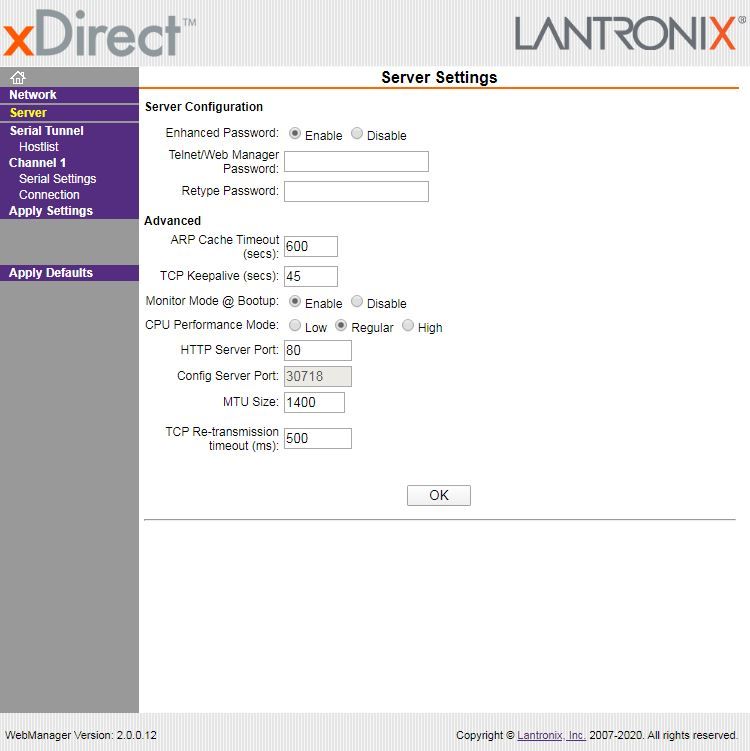
Set DNS Server IP Address _________________________________________________ 41
           Change Telnet Configuration Password ________________________________________42
           DHCP Name _____________________________________________________________ 42

       8: Setup Mode: Channel Configuration                                                43
           Channel 1 (Option 1) _______________________________________________________ 43
           Baudrate ________________________________________________________________ 43
           I/F (Interface) Mode ________________________________________________________ 44
           Flow ___________________________________________________________________ 44
           Port Number _____________________________________________________________ 45
           Connect Mode ___________________________________________________________45
                a) Incoming Connection _________________________________________________ 46
                b) Response __________________________________________________________47
                c) Active Startup _______________________________________________________ 47
                Host List Option (Hostlist) ________________________________________________ 48
                d) Datagram Type ______________________________________________________ 49
                e) Modem Mode _______________________________________________________ 49
           Send the Escape Sequence (+++) in Modem Mode _______________________________ 51
           Show IP Address after 'RING' ________________________________________________ 51
           Auto Increment Source Port _________________________________________________ 52
           Remote IP Address _______________________________________________________ 52
           Remote Port _____________________________________________________________ 52
           Disconnect Mode (DisConnMode) ____________________________________________ 52
           Flush Mode (Buffer Flushing) ________________________________________________ 53
           Pack Control _____________________________________________________________ 54
                Packing Interval _______________________________________________________ 54
                Trailing Characters ____________________________________________________54
                Send Characters ______________________________________________________ 54
           DisConnTime (Inactivity Timeout) _____________________________________________55
           Send Characters _________________________________________________________ 55
           Telnet Terminal Type ______________________________________________________ 55
           Channel (Port) Password ___________________________________________________ 55

       9: Setup Mode: Advanced Settings                                                    56
           Expert Settings (Option 5) ___________________________________________________ 56
              TCP Keepalive Time In Seconds __________________________________________ 56
              ARP Cache Timeout In Seconds __________________________________________ 56
              CPU Performance _____________________________________________________56
              Monitor Mode at Bootup _________________________________________________ 57
              HTTP Port Number _____________________________________________________57
              MTU Size ____________________________________________________________ 57
              TCP Re-Transmission Timeout ___________________________________________ 57
              Enable Alternate MAC __________________________________________________ 57

xDirect Serial-to-Ethernet Device Server User Guide                                          5
Ethernet Connection Type _______________________________________________ 57
           Security Settings (Option 6) _________________________________________________ 57
              Disable SNMP ________________________________________________________ 58
              SNMP Community Name ________________________________________________ 58
              Disable Telnet Setup ___________________________________________________ 58
              Disable TFTP Firmware Update __________________________________________ 59
              Disable Port 77FE (Hex) ________________________________________________ 59
              Disable Web Server ____________________________________________________59
              Disable Web Setup _____________________________________________________59
              Enable Telnet Authentication _____________________________________________59
              Disable ECHO Ports ____________________________________________________59
              Enable Encryption _____________________________________________________59
              Enable Enhanced Password _____________________________________________60
           Default Settings (Option 7) __________________________________________________ 61
              Channel 1 Configuration Defaults __________________________________________ 61
              Expert Settings Defaults _________________________________________________ 61
              Security Settings Defaults _______________________________________________ 61

       10: Firmware Upgrades                                                                   63
           Obtaining Firmware ________________________________________________________ 63
           Reloading Firmware _______________________________________________________ 63
               Using TFTP: Graphical User Interface ______________________________________ 63
               Using TFTP: Command Line Interface ______________________________________ 64
               Recovering the Firmware Using the Serial Port and DeviceInstaller _______________ 64

       11: Monitor Mode                                                                        66
           Entering Monitor Mode Using the Serial Port ____________________________________ 66
           Entering Monitor Mode Using the Network Port __________________________________66
           Monitor Mode Commands ___________________________________________________ 67

       Appendix A: Troubleshooting and Contact Info                                            69
           LEDs ___________________________________________________________________ 69
              Status LED ___________________________________________________________69
              Serial LEDs ___________________________________________________________70
              RJ45 Ethernet LED _____________________________________________________70
           Problems and Error Messages _______________________________________________ 70
           Technical Support _________________________________________________________ 73

       Appendix B: Connections and Pinouts                                                     74
           Serial Port Pinouts ________________________________________________________ 74
           Ethernet Connector Pinouts _________________________________________________ 75
           Power Jack (Mini USB-B) ___________________________________________________ 76

xDirect Serial-to-Ethernet Device Server User Guide                                              6
Appendix C: Technical Specifications                                            77

       Appendix D: Alternative Ways to Assign an IP Address                            79
           DHCP __________________________________________________________________79
           AutoIP __________________________________________________________________79
           BOOTP _________________________________________________________________80
           ARP and Telnet __________________________________________________________80

       Appendix E: Binary to Hexadecimal Conversions                                   81
           Converting Binary to Hexadecimal ____________________________________________ 81
              Conversion Table ______________________________________________________ 81
              Scientific Calculator ____________________________________________________81

       Appendix F: Compliance                                                          83
           RoHS, REACH and WEEE Compliance Statement _______________________________ 84

xDirect Serial-to-Ethernet Device Server User Guide                                      7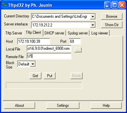
List of Figures

   Figure 2-1 Serial Tunneling Example ________________________________________________ 13
   Figure 2-2 Direct TCP/IP or Redirector Configuration ____________________________________ 13
   Figure 2-3 Product Label __________________________________________________________15
   Figure 2-4 Sample Hardware Address ________________________________________________ 15
   Figure 3-1 xDirect with PoE Connected to a Serial Device and Network ______________________ 16
   Figure 3-2 Standard xDirect (without PoE) Connected to a Serial Device and Network __________ 16
   Figure 5-1 Lantronix Web Manager __________________________________________________ 24
   Figure 5-2 Network Settings ________________________________________________________ 25
   Figure 5-3 Server Settings _________________________________________________________ 27
   Figure 5-4 Hostlist Settings ________________________________________________________ 29
   Figure 5-5 Channel Serial Settings __________________________________________________ 30
   Figure 5-6 TCP Connection Settings _________________________________________________ 32
   Figure 5-7 UDP Connection Settings _________________________________________________ 35
   Figure 5-8 Apply Settings and Apply Defaults __________________________________________ 36
   Figure 6-1 MAC Address and Login Prompt ___________________________________________ 37
   Figure 6-2 Setup Menu Options _____________________________________________________38
   Figure 7-1 Network Settings ________________________________________________________ 40
   Figure 8-1 Serial Port Settings ______________________________________________________ 43
   Figure 8-8 Host List Option (Hostlist) _________________________________________________ 48
   Figure 9-1 Expert Settings _________________________________________________________ 56
   Figure 9-2 Security Settings ________________________________________________________ 58
   Figure 10-2 TFTP Window ________________________________________________________ 64
   Figure 11-1 MAC Address and Login Prompt __________________________________________ 66
   Figure A-1 xDirect LEDs ___________________________________________________________69
   Figure B-1 Single Serial Port and Ethernet Port on xDirect ________________________________ 74
   Figure B-2 DB9F in RS232 Mode (All Models) __________________________________________ 74
   Figure B-3 DB9F in RS422/485 (4-Wire) Mode (xDirect485 & PoE Models) ___________________ 74
   Figure B-4 DB9F in RS485 (2-Wire) Mode (xDirect485 & PoE Models) _______________________ 75
   Figure B-5 RJ45 Ethernet Connector _________________________________________________ 75
   Figure B-7 Mini USB Power Port Connector on Standard xDirect Units _______________________ 76
   Figure E-2 Windows Scientific Calculator ______________________________________________82
    Figure E-3 Hexadecimal Values in the Scientific Calculator _______________________________ 82

xDirect Serial-to-Ethernet Device Server User Guide                                              8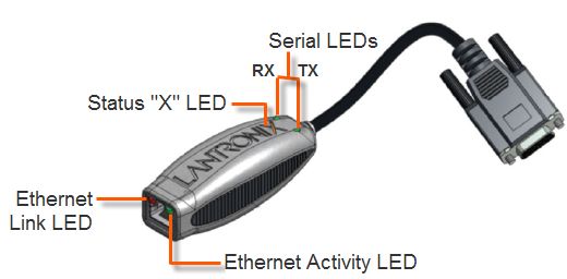
List of Tables

   Table 4-1 xDirect Configuration in DeviceInstaller _______________________________________19
   Table 7-2 BootP/DHCP/AutoIP options _______________________________________________ 40
   Table 7-3 Standard IP Network Netmasks _____________________________________________41
   Table 8-2 Interface Mode Options ___________________________________________________ 44
   Table 8-3 Common Interface Mode Settings ___________________________________________ 44
   Table 8-4 Flow Control Options _____________________________________________________45
   Table 8-5 Reserved Port Numbers __________________________________________________ 45
   Table 8-6 Connect Mode Options ___________________________________________________ 46
   Table 8-7 Manual Connection Address Example ________________________________________47
   Table 8-9 Modem Mode Messages __________________________________________________ 50
   Table 8-10 Modem Mode Commands ________________________________________________ 51
   Table 8-11 Disconnect Mode Options ________________________________________________ 53
   Table 8-12 Flush Mode Options _____________________________________________________53
   Table 8-13 Pack Control Options ____________________________________________________54
   Table 10-1 Firmware Files _________________________________________________________ 63
   Table 11-2 Monitor Mode Commands ________________________________________________ 67
    Table 11-3 Command Response Codes ______________________________________________68
    Table A-2 Status LED _____________________________________________________________ 69
    Table A-3 Serial LEDs_____________________________________________________________ 70
    Table A-4 Ethernet Link LED _______________________________________________________ 70
    Table A-5 Ethernet Activity LED _____________________________________________________70
    Table A-6 Problems and Error Messages ______________________________________________70
    Table B-6 Ethernet RJ45 Connector Pin-Outs __________________________________________ 75
    Table C-1 xDirect Technical Specifications_____________________________________________77
    Table E-1 Binary to Hexadecimal Conversion __________________________________________ 81

xDirect Serial-to-Ethernet Device Server User Guide                                          9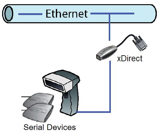
1:     Using this Guide

Purpose and Audience
       This guide provides the information needed to configure, use, and update the Lantronix®
       xDirect™ serial-to-Ethernet device server. It is for system administrators and those responsible for
       installing and maintaining the xDirect device server.

Chapter Summary
       The remaining chapters in this guide include:
         Chapter                      Description
         Chapter 2: Introduction      Describes the main features of the xDirect and the protocols it supports.
         Chapter 3: Installation of   Provides information for installing your unit and getting it up and running
         xDirect                      using DeviceInstaller or a serial port connection.
         Chapter 4: Using             Instructions for viewing the current configuration using DeviceInstaller.
         DeviceInstaller
         Chapter 5: Configuration     Details using the Web Manager to set parameters such as port and server
         Using Web Manager            properties.
         Chapter 6: Configuration Via Provides instructions for accessing Setup Mode (command line interface)
         Telnet or Serial Port (Setup using a Telnet connection through the network or a terminal or terminal
         Mode)                        emulation program through the serial port.
         Chapter 7: Setup Mode:       Details the network (server) settings
         Server Configuration
         Chapter 8: Setup Mode:       Details the serial port settings.
         Channel Configuration
         Chapter 9: Setup Mode:       Details expert and security settings and explains how to reset the unit to
         Advanced Settings            factory default values.
         Chapter 10: Firmware         Provides instructions for obtaining the latest firmware and updating the
         Upgrades                     xDirect.
         Chapter 11: Monitor Mode     Provides instructions for accessing and using the command line interface to
                                      monitor the network and diagnose problems.
         Appendix A: Troubleshooting Describes common problems and error messages and how to contact
         and Contact Info            Lantronix Technical Support.
         Appendix B: Connections      Provides descriptions and illustrations of connection hardware.
         and Pinouts
         Appendix C: Technical        Lists technical specifications for the xDirect.
         Specifications
         Appendix D: Alternative      Provides detailed information about using DHCP, AutoIP, BOOTP, ARP,
         Ways to Assign an IP         and Telnet to assign an IP address.
         Address
         Appendix E: Binary to        Provides instructions for converting binary values to hexadecimals.
         Hexadecimal Conversions
         Appendix F: Compliance       Provides Lantronix compliance information.

xDirect Serial-to-Ethernet Device Server User Guide                                                                 10
1: Using this Guide
Additional Documentation
Visit the Lantronix Web site at www.lantronix.com/support/documentation for the latest
documentation and the following additional documentation.
Document Description
xDirect Serial-to-Device Server Provides the steps for getting the xDirect device server up and running.
Quick Start
DeviceInstaller Online Help Provides instructions for using the Windows-based utility to configure
the xDirect and other Lantronix device servers.
“Live” Tutorials on the Explain and demonstrate assigning an IP address to the xDirect and
Lantronix Web Site (English) setting up the xDirect and Com Port Redirector.
See http://ltxfaq.custhelp.com/app/answers/detail/a_id/1119.
Com Port Redirector User Provides information on using the Windows-based utility to create a
Guide virtual com port.
xDirect Serial-to-Ethernet Device Server User Guide 112: Introduction
The xDirect is a sleek and compact Serial-to-Ethernet device server, providing quick and easy
Ethernet connectivity to virtually any device or machine with a serial interface. With an integrated
Ethernet port and serial cable, multiple power options including PoE, and an industry-best five
year warranty, xDirect provides a portable, extremely flexible, and highly affordable network
connectivity solution in the market. xDirect comes with a built-in web server that enables users to
access and configure the unit using a standard web browser on a PC, smartphone, or tablet from
anywhere. With plug-and-play simplicity, small form factor, multiple power options, and a robust
device server application, xDirect provides the easiest and shortest path to network connectivity
‘right on the wire’.
Key Features
Complete Network Connectivity Solution
Integrated 10/100 Ethernet Port and Serial Cable
Complete Device Server Application with Full IP Stack and Web Server
Space Saving Form Factor
Serial Data Rate of up to 921 Kbps1
128/192/256-bit AES Encryption
Flexible Power Options: 5 VDC USB Jack, 5-15 VDC DB9 Pin 9, and PoE2
Extended Temperature Range of -40° to 85°C3
5-year Limited Warranty
Short cable
256-bit AES Encryption
Password Protection
Applications
The xDirect family of Device Servers allows serial devices, such as those listed below, to connect
and communicate over Ethernet networks using the IP protocol family (TCP for connection-
oriented stream applications and UDP for datagram applications).
ATM Machines
CNC Controllers
Data Collection Devices
Automation Control
Data Display Devices/Digital Signage
1.When high performance mode in server settings is enabled.
2.PoE model only.
3.Non-PoE models only (UL certified -40° to +75°C).
xDirect Serial-to-Ethernet Device Server User Guide 122: Introduction
HVAC Systems
Medical Devices
Oil and Gas Exploration
Security Alarms and Access Control Devices
Telecommunications Equipment
Time/Attendance Clocks and Terminals
Universal Power Supply (UPS) Management Units
Using a method called serial tunneling, the xDirect encapsulates serial data into packets and
transports them over Ethernet. Using two xDirect units, connected by a network, virtual serial
connections can extend across a facility or around the world.
Figure 2-1 Serial Tunneling Example
The Com Port Redirector software available for download at
www.lantronix.com/support/downloads simplifies the integration process by extending the
functionality of COM-port-based Windows™ applications. Virtual COM ports, mapped to remote
device servers on the network, can replace direct serial connections.
Figure 2-2 Direct TCP/IP or Redirector Configuration
Note: For step-by-step instructions on configuring the xDirect for serial tunneling or for
use with the Com Port Redirector, see xDirect Configuration Tutorials on the Lantronix
web site: www.lantronix.com/support.
xDirect Serial-to-Ethernet Device Server User Guide 132: Introduction
Protocol Support
The xDirect uses the Internet Protocol (IP) for network communications and the Transmission
Control Protocol (TCP) to assure that no data is lost or duplicated and that everything sent to the
connection arrives correctly at the target.
Supported protocols include:
ARP, UDP/IP, TCP/IP, BOOTP, ICMP, Telnet, TFTP, AutoIP, DHCP, HTTP, and SNMP for
network communications.
TCP/IP, UDP/IP, and Telnet for connections to the serial port as well as Telnet Com Port
Control.
TFTP for firmware updates.
IP for addressing, routing, and data block handling over the network.
User Datagram Protocol (UDP) for typical datagram applications in which devices interact with
other devices without a point-to-point connection.
Additional Features
Modem Emulation: In modem emulation mode, the xDirect can replace dial-up modems. The unit
accepts modem AT commands on the serial port and then establishes a network connection to the
end device. This arrangement leverages network connections and bandwidth to eliminate
dedicated modems and phone lines.
Built-in Web Server: The xDirect includes a built-in web server for configuring the unit and
displaying operating and troubleshooting information on the attached links to online support.
Security Features: Password Protection and 256-bit AES Encryption
Configuration Methods
After installation, the xDirect requires configuration. For the unit to operate correctly on a network,
it must have a unique IP address on the network. There are three basic methods for logging into
the xDirect and assigning IP addresses and other configurable settings:
Web Manager: View and configure all settings easily through a web browser using the
Lantronix Web Manager. See Chapter 5: Configuration Using Web Manager.
DeviceInstaller: Configure the IP address and related settings and view current settings on
the xDirect using a Graphical User Interface (GUI) on a PC attached to a network. You will
need the latest version of DeviceInstaller. See Chapter 4: Using DeviceInstaller.
Serial and Telnet Ports: Use Setup Mode, a command line interface. There are two
approaches to accessing Setup Mode: making a Telnet connection to the network port (9999)
or connecting a terminal (or a PC running a terminal emulation program) to the unit's serial
port. See Chapter 6: Configuration Via Telnet or Serial Port (Setup Mode).
xDirect Serial-to-Ethernet Device Server User Guide 142: Introduction
Product Information Label
The product information label on the unit contains the following information about the specific unit:
Part Number
Revision
Note: The hardware address on the
Manufacturing Date Code label is also the product serial number.
The hardware address on the label is the
Product Model address for the Ethernet (eth0) interface.
Country of Origin
Lantronix Datamatrix Barcode (this includes the Device ID)
MAC Address (also used as Serial Number)
Figure 2-3 Product Label
The first three bytes of the hardware address are fixed and identify the unit as a Lantronix product.
The fourth, fifth, and sixth bytes are unique numbers assigned to each unit.
Figure 2-4 Sample Hardware Address
00-80-A3-14-01-18 or 00:80:A3:14:01:18
xDirect Serial-to-Ethernet Device Server User Guide 153: Installation of xDirect
This chapter describes how to install your xDirect and get it up and running in the shortest possible
time.
Package Contents
Verify and inspect the contents of the xDirect package using the following list. If any item is
missing or damaged, contact your place of purchase immediately.
xDirect
Power supply*
Note: *Power supply available for non-Power Over Ethernet (PoE) units only.
Quick Start Guide
Installing the xDirect
Figure 3-1 xDirect with PoE Connected to a Serial Device and Network
Figure 3-2 Standard xDirect (without PoE) Connected to a Serial Device and Network
To install the unit:
Note: See the Connections and Pinouts for details about connectors and pinouts.
1. Connect a serial device to your xDirect.
2. Connect an Ethernet cable to the RJ45 port.
3. For the xDirect PoE version, power is supplied to your unit over the Ethernet interface using an
802.3af PoE-compliant power source such as a PoE mid-span or PoE Ethernet switch.
Note: xDirect is a PoE Power Device, Class 1. For indoor use only. Do not connect
to PoE networks with cable routing to the outside plant!
xDirect Serial-to-Ethernet Device Server User Guide 163: Installation of xDirect
4. For non-PoE xDirect unit, supply power to your unit using the power supply that was included
in the packaging.
Note: The provided power supply is 5 VDC 1A. For all xDirect units power can also
be supplied via pin 9 (+) and pin 5 (-) on the DB9F connector (voltage range = 5 VDC
to 15 VDC). The xDirect will draw 1.3W max power.
Required Information
Before configuring the xDirect, have the following information available:
Hardware Address
Take note of the unit’s hardware address (also known as the Ethernet or MAC address). It is on
the product label, in the format: 00-80-A3-XX-XX-XX, where the XXs are unique numbers
assigned to the product (see Product Information Label).
Hardware Address: _____-_____-_____-_____-_____-_____
IP Address
The xDirect must have a unique IP address on your network. This address references the specific
unit. By default, the unit is DHCP-enabled and automatically assigned an IP address on DHCP-
enabled networks. If you are assigning a static IP address, the systems administrator generally
provides the IP address, subnet mask, and gateway.
Note: The factory default IP address is 0.0.0.0 to enable DHCP, BOOTP, and AutoIP.
When the units boots, it sends a DHCP broadcast to try and get an IP address. If it
receives no reply from a DHCP server, the xDirect tries BOOTP. If the xDirect does not
receive a response from BOOTP, it reverts to an AutoIP address.
IP Address: _______ _______ _______ _______
Subnet Mask: _______ _______ _______ _______
Gateway: _______ _______ _______ _______
You have several options for assigning an IP address and related network settings to your unit.
This chapter provides information about using the DeviceInstaller (graphical user interface) and
serial port login (command line interface) methods.
Note: For information about other methods of assigning the IP address, such as DHCP,
AutoIP, ARP, and Telnet, see Appendix D: Alternative Ways to Assign an IP Address.
xDirect Serial-to-Ethernet Device Server User Guide 174: Using DeviceInstaller
This chapter covers the steps for getting the xDirect device server online and for viewing its
current configuration.
Note: DeviceInstaller is a free utility program provided by Lantronix that discovers,
configures, upgrades, and manages Lantronix Device Servers. It can be downloaded from
the Lantronix website at www.lantronix.com/support/downloads.
For instructions on using DeviceInstaller to configure the IP address and related settings
or for more advanced features, see the DeviceInstaller Online Help.
By default, the username is “admin” and the password is the last 8 characters of the Device ID (for
devices manufactured after January 1, 2020) or is left blank (for all older devices).
Installing DeviceInstaller
To install DeviceInstaller:
1. Download the latest version of DeviceInstaller from
http://www.lantronix.com/support/downloads.
2. Run the executable to start the installation process.
3. Respond to the installation wizard prompts. (If prompted to select an installation type, select
Typical).
Assigning an IP Address
The unit’s IP address must be configured before it can work correctly on a network. The unit’s IP
address is normally set to 0.0.0.0 at the factory. The hardware address is on the product label. The
unit is DHCP enabled as the default.
To assign an IP address manually:
1. Click StartPrograms LantronixDeviceInstallerDeviceInstaller. If your PC has
more than one network adapter, a message displays. Select an adapter and click OK.
Note: If the unit already has an IP address (e.g., DHCP has assigned an IP
address), click the Search icon and select the unit from the list of Lantronix device
servers on the local network.
2. Click Tools Enter Global Credentials. Select Prompt with a dialog box to login and
click OK.
3. Note the IP address. You can put the IP address in the address bar of a browser to access
Web Manager and proceed to assign an IP address in the network settings. See Chapter 5:
Configuration Using Web Manager for more information. Alternatively, continue with these steps.
4. Click the Assign IP icon.
5. If prompted, enter the hardware address (on the product label) and click Next.
6. Select Assign a specific IP address and click Next.
7. Enter the IP address. The Subnet mask displays automatically based on the IP address; if
xDirect Serial-to-Ethernet Device Server User Guide 184: Using DeviceInstaller
desired, you may change it. On a local network, you can leave the Default gateway blank (all
zeros). Click Next.
8. Click the Assign button and wait several seconds until a confirmation message displays. Click
Finish.
9. Select the device from the main window list and select Ping from the Tools menu. The Ping
Device dialog box shows the IP address of the selected unit.
10. From the Tools menu, click the Ping button. The results display in the Status window. Click
the Clear Status button to clear the window so you can ping the device again.
Note: If you do not receive “Reply” messages, make sure the unit is attached to the
network properly and the IP address assigned is valid for the particular network
segment you are working with. If you are not sure, check with your systems
administrator.
11. Click the Close button to close the dialog box and return to the main window.
Adding the Unit to the Manage List
Now add the unit to the list of similar Lantronix devices on the network so you can manage and
configure it. To perform this step, click the Search icon.
DeviceInstaller locates the unit and adds it to the list. Now you can manage (configure) the unit so
it works with the serial device on the network.
Accessing the xDirect Using DeviceInstaller
1. Click StartPrograms LantronixDeviceInstallerDeviceInstaller.
2. Click the xDirect folder. The list of available Lantronix xDirect devices displays.
3. Expand the list of xDirects by clicking the + symbol next to the xDirect icon. Select the xDirect
unit by clicking on its IP address to view its configuration.
Viewing the Current Configuration
DeviceInstaller provides a view of the unit's configuration.
To view the unit's current settings:
1. Follow the instructions above to locate the xDirect.
2. In the right pane, click the Device Details tab. The current xDirect configuration displays.
Table 4-1 xDirect Configuration in DeviceInstaller
Current Settings Description
Name Configurable field. A name that identifies the xDirect. The name field is
blank by default. Double-click the field, type in the value, and press
Enter to complete. This name is not visible on other PCs or laptops
using DeviceInstaller.
xDirect Serial-to-Ethernet Device Server User Guide 194: Using DeviceInstaller
Current Settings (continued) Description
DHCP Device Name Non-configurable field. Displays the name associated with xDirect’s
current IP address, if the IP address was obtained dynamically.
To change the DHCP device name, see Chapter 5: Configuration Using
Web Manager or Chapter 6: Configuration Via Telnet or Serial Port
(Setup Mode).
Group Configurable field. A group name to categorize the xDirect. Double-click
the field, type in the value, and press Enter to complete. This group
name is not visible on other PCs or laptops using DeviceInstaller.
Comments Configurable field. Information about the xDirect. Double-click the field,
type in the value, and press Enter to complete. This description or
comment is not visible on other PCs or laptops using DeviceInstaller.
Device Family Non-configurable field. Displays the xDirect’s device family as xDirect.
Type Non-configurable field. Displays the device type as XDT232 or XDT485.
ID Non-configurable field. Displays the xDirect’s ID embedded within the unit.
Hardware Address Non-configurable field. Displays the xDirect’s hardware (or MAC)
address.
Firmware Version Non-configurable field. Displays the firmware currently installed on the
xDirect.
Extended Firmware Version Non-configurable field. Displays the full version nomenclature of the
firmware.
Online Status Non-configurable field. Displays the xDirect’s status as online, offline,
unreachable (the xDirect is on a different subnet), or busy (the xDirect is
currently performing a task).
IP Address Non-configurable field. Displays the xDirect’s current IP address. To
change the IP address, see Assigning an IP Address.
IP Address was Obtained Non-configurable field. Displays “Dynamically” if the xDirect automatically
received an IP address (e.g., from DHCP). Displays “Statistically” if the
IP address was configured manually. If the IP address was assigned
dynamically, the following fields appear:
Obtain with DHCP with value of True or False
Obtain with BOOTP with value of True or False
Obtain with RARP with value of True or False
Obtain with Auto IP with value of True or False
Subnet Mask Non-configurable field. Displays the xDirect’s current subnet mask. To
change the subnet mask, see Assigning an IP Address.
Gateway Non-configurable field. Displays the xDirect’s current gateway. To change
the gateway, see Assigning an IP Address.
Number of COB partitions Non-configurable field. Displays the number of COB partitions supported.
supported
Number of Ports Non-configurable field. Displays the number of ports on the xDirect.
TCP Keepalive Non-configurable field. Displays the xDirect’s TCP keepalive value. The
value is in the range 1-65s, and the default setting is 45.
Telnet Supported Non-configurable field. Indicates if Telnet sessions are permitted.
Displays True.
Telnet Port Non-configurable field. Displays the xDirect’s port for telnet sessions.
Web Port Non-configurable field. Displays the xDirect’s port for Web Manager
configuration.
xDirect Serial-to-Ethernet Device Server User Guide 204: Using DeviceInstaller
Current Settings (continued) Description
Maximum Baud Rate Non-configurable field. Displays the xDirect’s maximum baud rate.
Supported
Note: The xDirect may not currently be running at this rate.
Firmware Upgradable Non-configurable field. Displays True, indicating the xDirect’s firmware is
upgradable as newer version become available.
Supports Configurable Pins Non-configurable field. Displays False.
Supports Email Triggers Non-configurable field. Displays False.
Supports AES Data Stream Non-configurable field. Displays True. xDirect supports AES encryption
Supports 485 Non-configurable field. xDirect supports the RS-485 protocol. Displays:
False for XDT232.
True for XDT485.
Supports 921K Baud Rate Non-configurable field. Displays True. xDirect supports baud rates up to
921600 bits per second (bps).
Supports HTTP Server Non-configurable field. Displays True.
Supports HTTP Setup Non-configurable field. Displays True.
Supports 230K Baud Rate Non-configurable field. Displays True. xDirect supports a baud rate of
230400.
Supports GPIO Non-configurable field. Displays False, indicating the xDirect does not
support General Purpose Input Output (GPIO).
Next Step
Now that the xDirect unit has an IP address and other initial settings, you can configure it.
1. Double-click the unit in the list. Details about the unit display.
2. You have the following options:
To configure the unit using a Web browser, click the Web Configuration tab. The Lantronix
Web Manager window displays in your browser. Continue with Chapter 5: Configuration
Using Web Manager.
Note: To assign Expert and Security settings, you must use the Setup Mode
window in a Telnet session.
To configure the unit using a Telnet session, click the Telnet Configuration tab. The Setup
Mode window displays. Continue with Chapter 6: Configuration Via Telnet or Serial Port
(Setup Mode).
Assigning the IP Address: Serial Port Login
To assign the IP address and other network settings using a serial connection:
1. Connect a console terminal or a PC running a terminal emulation program to the unit's serial
port. The default serial port settings are 9600 baud, 8 bits, no parity, 1 stop bit, no flow
control.
2. To enter Setup Mode, cycle the unit's power (power off and back on). After power-up, the self-
test begins and the red Diagnostic LED starts blinking. You have one second to enter three
lowercase x characters.
xDirect Serial-to-Ethernet Device Server User Guide 214: Using DeviceInstaller
Note: The easiest way to enter Setup Mode is to hold down the x key at the terminal
(or emulation) while powering up the unit.
3. Select 0 (Server Configuration) and follow the prompts until you get to IP address.
4. Enter the new IP address, subnet mask, and gateway (if applicable).
5. Do one of the following:
Continue with Chapter 6: Configuration Via Telnet or Serial Port (Setup Mode).
Select 9 to save and exit Setup Mode. The unit performs a power reset.
xDirect Serial-to-Ethernet Device Server User Guide 225: Configuration Using Web Manager
You must configure the unit so it can communicate on a network with your serial device. For
example, you must set the way the unit will respond to serial and network traffic, how it will handle
serial packets, and when to start or close a connection.
The unit’s configuration is stored in nonvolatile memory and is retained without power. You can
change the configuration at any time. The unit performs a reset after you change and store the
configuration.
In this chapter, we describe how to configure the xDirect using Web Manager, Lantronix’s
browser-based configuration tool. (For information on using Setup Mode, our command line
configuration interface, see Chapter 6: Configuration Via Telnet or Serial Port (Setup Mode).
Note: The examples in this section show a typical device. Your device may have
different configuration options.
Accessing xDirect Using DeviceInstaller
Note: For more information on DeviceInstaller, see Chapter 4: Using DeviceInstaller.
1. Run DeviceInstaller and search for the list of available Lantronix device servers.
2. Click Tools > Enter Global Credentials. Select Prompt with a dialog box to login and click
OK.
3. Click on the xDirect folder. The list of available xDirect products display.
4. Expand the list of xDirect units by clicking the + symbol next to the xDirect icon.
5. Select the xDirect unit by clicking its hardware address.
6. In the right pane, click the Web Configuration tab.
7. To view the xDirect’s Web Manager in the current DeviceInstaller window, click the Go button.
To open the Web Manager in a web browser, click the External Browser button.
Note: Alternatively, to open Web Manager, open your web browser and enter the IP
address of the xDirect.
A dialog box appears to prompt for a User Name and Password.
8. Enter your user name and password. The factory default username is "admin" and factory
default password is the last 8 characters of the Device ID (for devices manufactured after
January 1, 2020) or "PASS" (for all older devices). The Device Status page of Web Manager
displays.
Note: We recommend that you always use the enhanced password setting and
create a strong 16 character password. See Security Settings (Option 6) on page 57.
xDirect Serial-to-Ethernet Device Server User Guide 235: Configuration Using Web Manager
Figure 5-1 Lantronix Web Manager
9. Navigate between pages by clicking links in the left pane of the Web Manager window.
xDirect Serial-to-Ethernet Device Server User Guide 245: Configuration Using Web Manager
Network Configuration
The unit’s network values display when you select Network from the main menu. The following
sections describe the configurable parameters on the Network Settings page.
Figure 5-2 Network Settings
Network Mode
1. Click Network from the main menu.
2. Note the following:
Network Mode For the xDirect, Wired Only is the only choice. It enables the Ethernet
network connectivity.
Automatic IP Address Configuration
An IP address can be assigned automatically. You then enter related network settings.
To assign an IP address automatically:
1. On the main menu, click Network.
2. Select Obtain IP address automatically.
3. Enter the following (as necessary):
BOOTP Select Enable to permit the Bootstrap Protocol (BOOTP) server to assign the IP
address from a pool of addresses automatically. Enable is the default.
DHCP Select Enable to permit the Dynamic Host Configuration Protocol (DHCP) to assign a
leased IP address to the xDirect unit automatically. Enable is the default.
xDirect Serial-to-Ethernet Device Server User Guide 255: Configuration Using Web Manager
AutoIP Select Enable to permit the xDirect to generate an IP in the 169.254.x.x address
range with a Class B subnet. Enable is the default.
DHCP Host Name Enter the name of the host on the network providing the IP address.
Note: Disabling BOOTP, DHCP, and AutoIP (all three checkboxes) is not advised as the
only available IP assignment method will then be ARP or serial port.
4. When you are finished, click the OK button.
5. On the main menu, click Apply Settings.
Static IP Address Configuration
You can manually assign an IP address to the unit and enter related network settings.
To assign an IP address manually:
1. On the main menu, click Network.
2. Select Use the following IP configuration.
3. Enter the following (as necessary):
IP Address If DHCP is not used to assign IP addresses, enter it manually in decimal-dot notation.
The IP address must be set to a unique value in the network.
Subnet Mask A subnet mask defines the number of bits taken from the IP address that are assigned
for the host part.
Default Gateway The gateway address, or router, allows communication to other LAN segments. The
gateway address should be the IP address of the router connected to the same LAN
segment as the unit. The gateway address must be within the local network.
DNS Server The DNS server allows the name of a remote machine to be resolved automatically.
Enter the IP address of the DNS server. If the device is DHCP enabled, the DHCP
server provides the DNS server IP address, which will override this configured value.
Note: This setting is applicable only in Manual Connection mode.
4. When you are finished, click the OK button.
5. On the main menu, click Apply Settings.
Ethernet Configuration
You must specify the speed and direction of data transmission.
To specify how data will be transmitted:
1. On the main menu, click Network.
2. Enter the following (as necessary):
Auto Negotiate With this option, the Ethernet port auto-negotiates the speed and duplex with the
hardware endpoint to which it is connected. This is the default.
If this option is not selected, complete the fields that become available:
Speed: The speed of data transmission. The default setting is 100 Mbps.
Duplex: The direction of data transmission. The default setting is Full.
3. When you are finished, click the OK button.
4. On the main menu, click Apply Settings.
xDirect Serial-to-Ethernet Device Server User Guide 265: Configuration Using Web Manager
Server Configuration
The unit’s server values display when you select Server from the main menu. The following
sections describe the configurable parameters on the Server Settings page.
Figure 5-3 Server Settings
To configure the xDirect device server settings:
1. On the main menu, click Server.
2. Configure or modify the following fields:
Server Configuration
Enhanced Password Select whether to enable advanced password:
Note: We recommend Enable: selecting this option enables advanced password creation,
that you always enable the allowing you to create passwords up to 16 bytes in length.
enhanced password Disable: selecting this option disables advanced password creation,
setting, and create a allowing you to create basic passwords up to 4 bytes in length.
strong 16 character
password. This is enabled
by default on devices
manufactured after
January 1, 2020.
Telnet/Web Manager Enter the password required for Telnet configuration and Web Manager
Password access. No password or entering a “blank” password entry will disable default
password protection.
Retype Password Re-enter the password required for Telnet configuration and Web Manager
access.
xDirect Serial-to-Ethernet Device Server User Guide 275: Configuration Using Web Manager
Advanced
ARP Cache Timeout (secs) When the unit communicates with another device on the network, it adds
an entry into its ARP table. ARP Cache timeout defines the number of
seconds (1-600) before it refreshes this table.
TCP Keepalive (secs) TCP Keepalive time defines how many seconds the unit waits during an
inactive connection before checking its status. If the unit does not receive
a response, it drops that connection. Enter a value between 0 and 60
seconds. 0 disables keepalive. The default setting is 45.
Monitor Mode @ Bootup Select Disable to disable entry into the monitor mode using the yyy or xx1
key sequence at startup. This field prevents the unit from entering monitor
mode by interpreting the stream of characters that are received during the
device server's initialization at startup. The default setting is Enable.
CPU Performance Mode Select the xDirect's performance mode. Higher performance settings
require more energy. Low is 26 MHz. Regular is 48 MHz; High is 88 MHz.
The default is Regular.
HTTP Server Port This option allows the configuration of the web server port number. The
valid range is 1-65535. The default setting is 80.
Config Server Port Not applicable for this product.
MTU Size The Maximum Transmission Unit (MTU) is the largest physical packet size
a network can transmit for TCP and UDP. Enter between 512 and 1400
bytes. The default setting is 1400 bytes.
TCP Re-transmission The desired TCP re-transmission timeout value. If the ACK is not received
timeout (ms) for a packet sent from the xDirect device, then the unit will retransmit the
data. The valid range is 500-4000 msec. The default is 500.
3. When you are finished, click the OK button.
4. On the main menu, click Apply Settings.
xDirect Serial-to-Ethernet Device Server User Guide 285: Configuration Using Web Manager
Host List Configuration
The xDirect scrolls through the host list until it connects to a device listed in the host list table. After
a successful connection, the unit stops trying to connect to any others. If this connection fails, the
unit continues to scroll through the table until the next successful connection.
The host list supports a minimum of 1 and a maximum of 12 entries. Each entry contains an IP
address and a port number.
Note: The host list is disabled for Manual and Modem Mode. The unit does not accept a
data connection from a remote device when the hostlist option is enabled.
To configure the host list:
1. On the main menu, click Hostlist.
Figure 5-4 Hostlist Settings
2. Enter or modify the following fields:
Retry Settings
Retry Counter Enter the value for the number of times the xDirect should attempt to retry
connecting to the host list. The default setting is 3.
Retry Timeout Enter the duration (in milliseconds) the xDirect should abandon attempting a
connection to the host list. The default setting is 250.
Host Information
Host Address Enter or modify the host’s IP address.
Port Enter the target port number.
3. When you are finished, click the OK button.
4. On the main menu, click Apply Settings.
xDirect Serial-to-Ethernet Device Server User Guide 295: Configuration Using Web Manager
Channel 1 Configuration
The Channel 1 configuration defines how the serial ports respond to network and serial
communication.
Serial Settings
To configure the channel’s serial settings:
1. On the main menu, click Serial Settings (under Channel 1) to display the Serial Settings
window.
Figure 5-5 Channel Serial Settings
2. In the available fields, enter the following information:
Channel 1
Disable Serial Port When selected, disables communication through the serial port. The serial
port is enabled by default.
Note: This feature is not available on single port device servers, since it
can only be applied to channel 1.
Port Settings
Protocol From the drop-down menu, select the protocol type for the selected
channel. The default setting is RS232.
Flow Control Flow control manages data flow between devices in a network to ensure it
is processed efficiently. Too much data arriving before a device is prepared
to manage it causes lost or retransmitted data. None is the default.
xDirect Serial-to-Ethernet Device Server User Guide 305: Configuration Using Web Manager
Baud Rate The unit and attached serial device, such as a modem, must agree on a
speed or baud rate to use for the serial connection. Valid baud rates are
300, 600, 1200, 2400, 4800, 9600, 19200, 38400, 57600, 115200, and
230400 baud. Additionally, 921600 and 460800 baud rates are available
when CPU is set to High. The default setting is 9600.
Data Bits Indicates the number of bits in a transmitted data package. The default
setting is 8.
Parity Checks for the parity bit. The default setting is None.
Stop Bits The stop bit follows the data and parity bits in serial communication. It
indicates the end of transmission. The default setting is 1.
Pack Control
Enable Packing Select to enable packing on the xDirect.
Two firmware-selectable packing algorithms define how and when packets are
sent to the network.
The standard algorithm is optimized for applications in which the unit is used in
a local environment, allowing for very small delays for single characters, while
keeping the packet count low.
The alternate packing algorithm minimizes the packet count on the network
and is especially useful in applications in a routed Wide Area Network (WAN).
Adjusting parameters in this mode can economize the network data stream.
Disabled by default.
Idle Gap Time Select the maximum time for inactivity. The default time is 12 milliseconds.
Match 2 Byte Sequence Use to indicate the end of a series of data to be sent as one group. The
sequence must occur sequentially to indicate end of the data collection to the
xDirect. The default setting is No.
Match Bytes Use to indicate the end of a series of data to be sent as one group. Set this
value to 00 if specific functions are not needed.
Send Frame Immediate After the detection of the byte sequence, indicates whether to send the data
frame or the entire buffer. Select Yes to send only the data frame. The default
setting is No.
Send Trailing Bytes Select the number of bytes to send after the end-of-sequence characters. The
default setting is None.
Flush Input Buffer (Serial to Network)
With Active Connect Select Yes to clear the input buffer with a connection that is initiated from
the device to the network. The default setting is No.
With Passive Connect Select Yes to clear the input buffer with a connection initiated from the
network to the device. The default setting is No.
At Time of Disconnect Select Yes to clear the input buffer when the network connection to or
from the device is disconnected. The default setting is No.
Flush Output Buffer (Network to Serial)
With Active Connect Select Yes to clear the output buffer with a connection that is initiated from
the device to the network. The default setting is No.
With Passive Connect Select Yes to clear the output buffer with a connection initiated from the
network to the device. The default setting is No.
xDirect Serial-to-Ethernet Device Server User Guide 31You can also read