GALAXY GX2 Operating Manual - Order No.: 10127150/02
←
→
Page content transcription
If your browser does not render page correctly, please read the page content below

Operating Manual

GALAXY® GX2
Automated Test System

                        Order No.: 10127150/02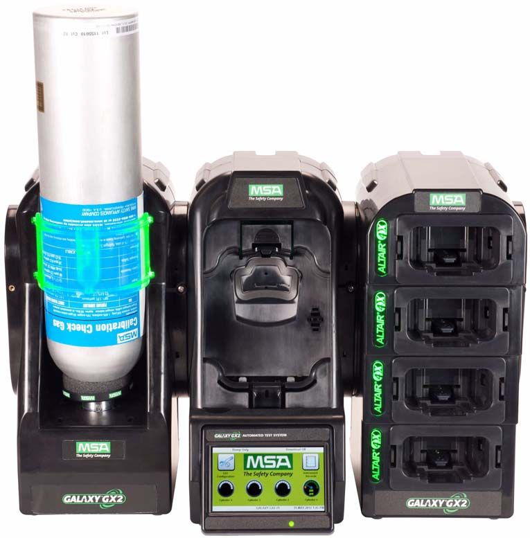
WARNING

Read this manual carefully before using the instrument. The instrument will perform as designed
only if it is used and maintained in accordance with the manufacturer's instruction. Otherwise, it
could fail to perform as designed and persons who rely on this instrument for their safety could
sustain serious personal injury or death.

                                         WARNING

Refer to the applicable gas detector(s) operating manual for proper set-up and operation.
Follow all local regulations and internal requirements relating to both the GALAXY GX2 System
and the gas detector. Misuse can result in serious personal injury or death.

1000 Cranberry Woods Drive
Cranberry Township, PA 16066
United States
Phone 1-800-MSA-2222
Fax 1-800-967-0398

For your local MSA contacts please go to our website www.MSAsafety.com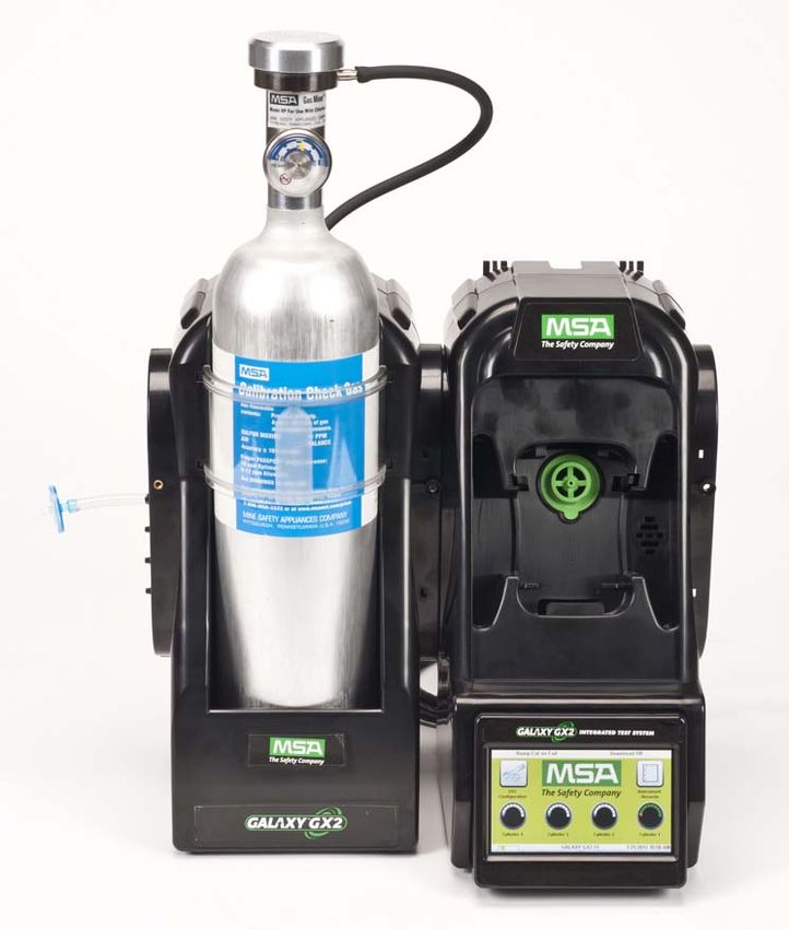
MSA AUER                                                                                                                              Contents

Contents
1    Safety Regulations ................................................................................................................... 5
    1.1     Correct Use .......................................................................................................................... 5
    1.2     Product Warranty ................................................................................................................. 6

2    Introduction ................................................................................................................................ 8
    2.1     Power Supply ..................................................................................................................... 10
    2.2     The Test Stand .................................................................................................................. 10
              SD or SDHC Memory Card Slot ...................................................................................... 11
              Test Stand Networked to a PC ........................................................................................ 11
              Test Stand is Stand-Alone ............................................................................................... 12
              USB Drives ...................................................................................................................... 13
    2.3     Ethernet Interface .............................................................................................................. 13
    2.4     Software Options ............................................................................................................... 14
    2.5     Cylinder Holder (electronic) ............................................................................................... 14
    2.6     Optional Printer .................................................................................................................. 15
    2.7     Optional Multi-Unit Charger ............................................................................................... 15
    2.8     Special Conditions for Use with Reactive Gases ............................................................... 16

3    Installation ................................................................................................................................ 18
    3.1     Connect Units in a Bank .................................................................................................... 19
    3.2     Connect a Test Gas Source Without a Cylinder Holder ..................................................... 20
    3.3     Network Test Stands .......................................................................................................... 20
    3.4     Removing Gas Seal for Certain ALTAIR and ALTAIR Pro Instruments ............................. 21
    3.5     Desktop Mounting .............................................................................................................. 22
    3.6     Wall Mounting .................................................................................................................... 24
    3.7     SD or SDHC Memory Card Option .................................................................................... 25

4    Setting Up the GALAXY GX2 System .................................................................................... 26
    4.1     Initial Setup ........................................................................................................................ 26
    4.2     Security Setup .................................................................................................................... 28
    4.3     Home Screen ..................................................................................................................... 28
    4.4     General Setup .................................................................................................................... 30
    4.5     GX2 Configuration ............................................................................................................. 31
              Backlight/Volume Setup .................................................................................................. 31
              GALAXY GX2 Setup ....................................................................................................... 36
              GX2 Gas Setup ............................................................................................................... 39
              Network Setup (Optional) ................................................................................................ 42
              Port Setup (Optional) ...................................................................................................... 43
    4.6     Instrument Configuration .................................................................................................... 43
              Instrument Setup ............................................................................................................. 45

US                                           GALAXY GX2 Automated Test System                                                                      3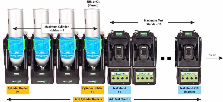
Contents                                                                                                                                 MSA

              Sensor Setup ................................................................................................................... 47
              Save Settings .................................................................................................................. 49
              Load/Delete Settings ...................................................................................................... 49
              Update Settings ............................................................................................................... 50
    4.7    Cylinder Configuration ........................................................................................................ 50
              Cylinder Setup ................................................................................................................. 51
              Expiration Setup .............................................................................................................. 52
              Special Conditions for Use with 100% LEL or Greater Methane Calibration Gas .......... 53

5     Using the GALAXY GX2 System ............................................................................................ 54
    5.1    Turning on the System ....................................................................................................... 54
    5.2    Inserting the Instrument ..................................................................................................... 54
    5.3    Running a Test ................................................................................................................... 55
    5.4    Classic Mode ...................................................................................................................... 59
    5.5    Automated Testing Features ............................................................................................. 59
              GALAXY GX2 Always Ready Feature ............................................................................. 59
              Time of Day Automated Testing ..................................................................................... 60
    5.6    E-mail Notification .............................................................................................................. 61
    5.7    Overdue Calibration and Bump Notification ....................................................................... 61

6    Troubleshooting ....................................................................................................................... 62
    6.1    Instrument Will Not Initiate a Bump or Calibration ............................................................. 62
    6.2    Instrument Fails Zero Calibration or Bump ........................................................................ 63
    6.3    Instrument Fails Span Calibration or Bump ....................................................................... 63
    6.4    Instrument Records Do Not Display ................................................................................... 63
    6.5    Cylinder Data Does Not Display ......................................................................................... 64
    6.6    Test Stand Yellow LED ...................................................................................................... 64
    6.7    System Error Messages ..................................................................................................... 66
    6.8    Automated Testing Does Not Occur .................................................................................. 67
              Time of Day is set on the GALAXY GX2 but no test occurred ......................................... 67
              My Altair 4X didn't calibrate when it was supposed to ..................................................... 67

7    Maintenance (Cleaning and Part Replacement) .................................................................... 68
    7.1    Corrective Maintenance ..................................................................................................... 68
    7.2    Replacement Parts and Accessories ................................................................................. 68
    7.3    Fresh Air Filter Replacement ............................................................................................. 72
    7.4    O-Ring Seal Replacement (Cylinder Holder) ..................................................................... 73
    7.5    Inlet Seal Replacement (ALTAIR 5/5X Gas Detector) ....................................................... 73
    7.6    Rubber Insert Replacement (ALTAIR Gas Detector) ......................................................... 75

8    Technical Specifications ......................................................................................................... 76

9    GALAXY GX2 Default Parameters .......................................................................................... 77

4                                           GALAXY GX2 Automated Test System                                                              US
MSA AUER                                                                             Safety Regulations

1     Safety Regulations

1.1   Correct Use

                                                WARNING

      Read this manual carefully before using the instrument. The instrument will perform as designed
      only if it is used and maintained in accordance with the manufacturer's instruction. Otherwise, it
      could fail to perform as designed and persons who rely on this instrument for their safety could
      sustain serious personal injury or death.

                                                WARNING

      (1)   Do not use silicone-type lubricants in assembling the GALAXY® GX2 Automated
            Test System and do not allow silicone vapors to be drawn into the flow system while in
            operation. Silicone can desensitize the combustible gas sensor, thereby giving erroneously
            low readings.

      (2)   Use the GALAXY GX2 System only in non-hazardous environments free of combustible
            concentrations of gases and vapors. System use with 100% LEL or greater methane is de-
            scribed in chapter 4.7 under Special Conditions for Use with 100% LEL or Greater Methane
            Calibration Gas.

      (3)   Use only genuine MSA replacement parts when performing any maintenance procedures
            on the GALAXY GX2 System. Substitution of components can seriously impair
            performance.
      Failure to follow the above can result in serious personal injury or loss of life.

               This device complies with Part 15 of the FCC Rules. Operation is subject to the
               following two conditions:
               (1) this device may not cause harmful interference, and
               (2) this device must accept any interference received, including interference that may
               cause undesired operation.
               This equipment has been tested and found to comply with the limits for a Class A digital
               device, pursuant to Part 15 of the FCC Rules. These limits are designed to provide rea-
               sonable protection against harmful interference when the equipment is operated in a
               commercial environment. This equipment generates, uses, and can radiate radio fre-
               quency energy and, if not installed and used in accordance with the instruction manual,
               may cause harmful interference to radio communications. Operation of this equipment
               in a residential area is likely to cause harmful interference in which case the user will be
               required to correct the interference at his own expense.

                                                NOTICE
      This is a class A product in accordance with CISPR 22. In a domestic environment, this product
      may cause radio interference, in which case the user may be required to take adequate
      measures.

 US                               GALAXY GX2 Automated Test System                                         5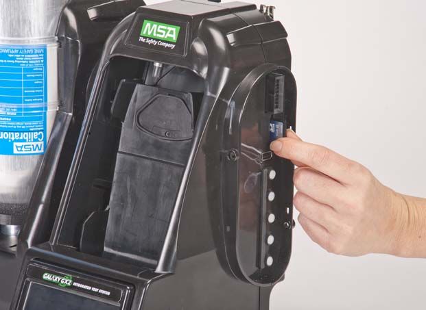
Safety Regulations                                                                                   MSA

      FCC Warning Statements

      Changes or modifications not expressly approved by the manufacturer could void the user's
      authority to operate the equipment.

      Industry Canada (IC) Warning Statements

      The installer of this radio equipment must ensure that the antenna is located or pointed such that
      it does not emit RF field in excess of Health Canada limits for the general population; consult
      Safety Code 6, obtainable from Health Canada's website www.hc-sc.gc.ca/rpb.

1.2   Product Warranty
      The warranties made by Mine Safety Appliances Company with respect to the product are voided
      if the product is not used and serviced in accordance with the instructions in this manual. Protect
      yourself and others by following them. We encourage our customers to contact MSA regarding
      this equipment prior to use or for any additional information relative to use or repairs.

      ITEM                                   WARRANTY PERIOD
      GALAXY GX2 Test Stand,                 MSA warrants that this product will be free from mechani-
      Cylinder Holder and Multi Unit         cal defects and faulty workmanship for a period of two (2)
      Charger                                years from date the product is first used, provided it is
                                             maintained and used in accordance with MSA's instruc-
                                             tions and/or recommendations. Warranty shall not exceed
                                             two years and six months from the date of manufacture.
      Optional Receipt/ Sticker Printer      1 year from ship date

      This warranty does not cover filters, fuses, etc. Certain other accessories not specifically listed
      here may have different warranty periods. This warranty is valid only if the product is maintained
      and used in accordance with Seller's instructions and/or recommendations. The Seller shall be re-
      leased from all obligations under this warranty in the event repairs or modifications are made by
      persons other than its own or authorized service personnel or if the warranty claim results from
      physical abuse or misuse of the product. No agent, employee or representative of the Seller has
      any authority to bind the Seller to any affirmation, representation or warranty concerning this prod-
      uct. Seller makes no warranty concerning components or accessories not manufactured by the
      Seller, but will pass on to the Purchaser all warranties of manufacturers of such components.

      THIS WARRANTY IS IN LIEU OF ALL OTHER WARRANTIES, EXPRESSED, IMPLIED OR
      STATUTORY, AND IS STRICTLY LIMITED TO THE TERMS HEREOF. SELLER
      SPECIFICALLY DISCLAIMS ANY WARRANTY OF MERCHANTABILITY OR OF FITNESS
      FOR A PARTICULAR PURPOSE.

6                                 GALAXY GX2 Automated Test System                                    US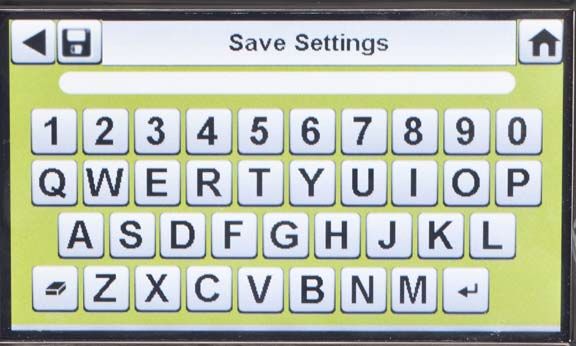
MSA AUER                                                                            Safety Regulations

     Exclusive Remedy

     It is expressly agreed that Purchaser's sole and exclusive remedy for breach of the above warran-
     ty, for any tortious conduct of Seller, or for any other cause of action, shall be the replacement at
     Seller's option, of any equipment or parts thereof, which after examination by Seller is proven to
     be defective. Replacement equipment and/or parts will be provided at no cost to Purchaser,
     F.O.B. Seller's Plant. Failure of Seller to successfully replace any nonconforming equipment or
     parts shall not cause the remedy established hereby to fail of its essential purpose.

     Exclusion of Consequential Damage

     Purchaser specifically understands and agrees that under no circumstances will seller be liable to
     purchaser for economic, special, incidental or consequential damages or losses of any kind what-
     soever, including but not limited to, loss of anticipated profits and any other loss caused by reason
     of nonoperation of the goods. This exclusion is applicable to claims for breach of warranty, tortious
     conduct or any other cause of action against seller.

US                               GALAXY GX2 Automated Test System                                       7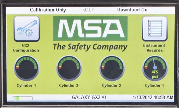
Introduction MSA
2 Introduction
Congratulations on purchasing the GALAXY GX2 Automated Test System, the next generation
Test Stand and instrument management system from MSA. This system is used exclusively with
the ALTAIR® family of gas detectors. This manual uses the terms instrument and gas detector
to represent that entire line of ALTAIR gas detection instruments.
In this manual the user will learn to install and configure the GALAXY GX2 Test Stand and optional
attachments, and test gas detectors. Maintenance, Troubleshooting, and Technical Specifications
sections are also provided.
The Test Stand uses a sophisticated internal processor and simple to use touch screen display
for the configuration of calibration parameters and gas detector settings, and for gathering instru-
ment data.
Each Test Stand and optional attachments can be wall or desk mounted to serve the needs of the
user. Constructed of durable composite polymers, this equipment is designed for normal indoor
applications and operates within a broad temperature range of 0º to 40ºC in non-condensing hu-
midity atmospheres.
The principal components of the GALAXY GX2 System include the Test Stand and optional elec-
tronic or non-electronic Cylinder Holder, Multi-Unit Charger, and Receipt/ Sticker Printer. These
components [ Fig. 1] are designed to be attached (excluding the printer), to avoid accidental
separation during operation.
Fig. 1 The GALAXY GX2 Automated Test System
8 GALAXY GX2 Automated Test System US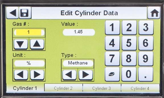
MSA AUER Introduction
The Test Stand is a standalone unit that can accommodate one gas detector of the ALTAIR family.
However, each Test Stand contains the plumbing and electronic ports to simultaneously connect
a total of 10 Test Stands and four Cylinder Holders (electronic or non-electronic).
For applications where multiple Cylinder Holders are connected, the Test Stand Expanded Sole-
noid option must be ordered. This option allows the Test Stand to open and close up to four Cyl-
inder Holder valves for gas detectors that may require multiple cylinders for test purposes. For
example, an ALTAIR 5/5X with the standard 4 sensors plus a toxic sensor likely requires two gas
cylinders.
The electronic Cylinder Holder is designed to read a Radio Frequency Identification (RFID) tag
embedded in a plastic ring on MSA test gas cylinders. The RFID tag contains cylinder parameters
that are necessary for successful calibration operations, providing the customer with an excep-
tionally easy setup experience. Gas cylinder information is automatically populated without user
intervention when using the RFID-tagged gas cylinders.
If MSA test gas cylinders are not used, the non-electronic version of the Cylinder Holder is avail-
able. This configuration [ Fig. 2] requires the user to manually enter cylinder parameters.
Fig. 2 Non-electronic Cylinder Holder and Test Stand.
A USB port is provided on the Test Stand that may be used with the GALAXY GX2 USB key to
change instrument settings via the touch screen. This function allows for convenient fleet
management capabilities. The port may also be used for an optional Receipt/ Sticker Printer, to
print calibration/bump stickers or paper receipts after an instrument test.
The primary functions of the Test Stand are to calibrate and bump the ALTAIR family of gas de-
tectors.
A Bump Test (or Function Check) is a qualitative check conducted by applying a known challenge
gas to the instrument. The purpose of this check is to confirm sensor functionality and to verify the
integrity of the flow path to the sensor(s). Perform a bump test prior to each day's use.
US GALAXY GX2 Automated Test System 9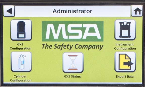
Introduction MSA
A successful calibration consists of the adjustment of the sensor('s) output to match the precise
concentration value of a known traceable calibration cylinder. A calibration can be performed at
any time to ensure maximum accuracy. A calibration should be performed periodically at regular
intervals and immediately if the unit fails a bump test.
See the instrument manual for specific conditions that require a more frequent bump or calibration
interval. Also see the instrument manual for information on checking the gas detector alarm func-
tions.
In the following sections of this manual the user will learn how to install the GALAXY GX2
Automated Test System, set up its functionality, and perform instrument tests. The hardware, soft-
ware, and configuration options anticipate the user's needs and provide superb efficiency in this
next generation Automated Test System.
GALAXY GX2 System Features and Options
The GALAXY GX2 System automatically identifies the type of gas detector inserted into the Test
Stand. Based on user-defined settings, the Test Stand then performs bump tests and/or calibrates
the instrument. The data collected from each test event is stored to a memory card
[ chapter 2.2] and/or optional MSA Link™ Pro software application for data analysis (refer to the
MSA Link Pro end-user manual).
2.1 Power Supply
The Test Stand supplies power to the attached electronic Cylinder Holders. The Test Stand and
Multi-Unit charger are powered individually by one of the following methods:
- Power Module: Input power requirements: 100 - 240 VAC, 47 - 63 Hz
(Several different prong types are available for world-wide AC sockets).
- Optional Vehicle Module 12/24 VDC (For use in a cigarette lighter socket).
NOTICE
Use of a power supply not specified by MSA will void the instrument warranty and could cause
damage to the GALAXY GX2 System.
2.2 The Test Stand
The Test Stand performs the following functions:
- Bump or calibration testing per user setup.
- Records test results to the optional memory card and to an optional networked PC interface.
- Sends gas detector Instrument Periodic and/or Session datalogs to a networked PC interface.
- Provides optional instrument charging capability.
- USB key allows gas detector settings to be changed securely, with the touch of the Test Stand
screen.
- Permits printing of test results to an instrument sticker or receipt, with the optional Receipt/
Sticker Printer.
- Sends e-mail notification of system alerts per user setup.
10 GALAXY GX2 Automated Test System USMSA AUER Introduction
An LED indicator shows the status of the Test Stand:
- Green light indicates that the Test Stand hardware and software are fully functional.
- Blinking green light indicates that the Test Stand is performing the user specified test or data-
log download.
- Blinking yellow light indicates that the Test Stand is in error and cannot be used for gas detec-
tor testing. Diagnostic information is available as described on the "GX2 Status" screen on the
Test Stand and in the Troubleshooting section of this manual [ chapter 6].
- Red light indicates that the last calibration or bump test failed.
3
4
5
1
2 6
Fig. 3 Test Stand Physical Features
1 Touch Screen Display 4 SD Card Port
2 Status LED 5 USB Port
3 Test Stand to Test Stand connector 6 Gas plugs
SD or SDHC Memory Card Slot
A memory card port is provided on the Test Stand for calibration and bump record storage. An
SD or SDHC memory card can be purchased from MSA (preferred) or from the following manu-
facturers:
- Kingston
- SanDisk
- Lexar
- Wintec
The data on an SD or SDHC memory card is encrypted for use with MSA Link™ Pro application.
There is also an application available on the MSA website to create a printable version of the SD
card records (MSA GALAXY GX2 SD Card Reader.exe).The type and amount of data recorded
to the memory card is contingent on whether the Test Stand is networked.
Test Stand Networked to a PC
If the network connection is lost, only calibration and bump records are saved to the memory card.
If networked and e-mail alerts are configured with MSA Link Pro, the Test Stand will generate an
email alert once the memory card reaches 90% and again at 99% capacity.
US GALAXY GX2 Automated Test System 11Introduction MSA
Test Stand is Stand-Alone
If the GALAXY GX2 Test Stand is not networked to MSA Link Pro, the memory card will save each
calibration and bump test record. Incomplete records will not be saved.
Once a memory card reaches full capacity, the Test Stand will be in fault and prohibit any unit from
performing tests in that bank, until corrected. The Test Stand can be configured to erase the
memory card, or the user can insert a replacement.
The memory card should only be removed when no test activity is occurring. Events that
occur while no memory card is installed will not be stored in the Test Stand.
If no memory card is used, only the most recent bump or calibration record is stored to
the Test Stand internal memory.
An optional end cap [ Fig. 4] can be placed over the port to protect the memory card and all
external connections.
Fig. 4 Optional End Cap
12 GALAXY GX2 Automated Test System USMSA AUER Introduction
USB Drives
Two optional USB Keys [ Fig. 5] are available for purchase with the GALAXY GX2
Automated Test System:
- GALAXY GX2 USB Key: This key is inserted in the USB port on the Test Stand in order to
change gas detector settings. The key ensures only authorized users can change settings on
ALTAIR gas detectors; a security step in addition to the four-digit password.
- MSA Link Pro Key: This key is used to enable the MSA Link Pro application on a single PC.
More information about this key can be found in the software product end-user manual.
Fig. 5 GALAXY GX2 USB Key and MSA Link Pro Key
2.3 Ethernet Interface
Two Ethernet Interfaces are provided on the rear of the GALAXY GX2 Test Stand [ Fig. 6]. The
ports allow for the connection and communication distribution between multiple Test Stands. If
networking to a computer, one Ethernet port on the Master Test Stand is used to communicate
with the MSA Link Pro software application.
Fig. 6 Test Stand Ethernet jacks
US GALAXY GX2 Automated Test System 13Introduction MSA
2.4 Software Options
The GALAXY GX2 System functions as a standalone system, but the optional MSA Link Pro soft-
ware application can be used to network the Test Stand to a PC through an Ethernet cable. This
application provides a best-in-class user interface and data analysis toolset to quickly identify is-
sues or concerns that require user action.
MSA Link Pro software provides the user:
- Database storage of instrument Periodic and Session datalogs.
- Automatic or customized reports from the collected data.
- Single glance notification of instruments that are overdue for calibration or bump test.
- Email notifications of GALAXY GX2 System and instrument warnings and error messages.
- Single setting configuration of all GALAXY GX2 units in a bank.
No need to individually configure each Test Stand.
Users may use the free MSA Link software application and an IR dongle
[ chapter 7.2] to communicate directly with their gas detector. MSA Link software
allows a user to upload and download instrument settings, and download datalogs.
To learn more about installing and using MSA Link Pro software, refer to the software product end-
user manual.
2.5 Cylinder Holder (electronic)
The electronic Cylinder Holder can accommodate one test gas cylinder and includes:
1
2
3
Fig. 7 Cylinder Holder Physical Features
1 Light Band 2 RFID Tag 3 Internal Pressure Regulator & Sensor
14 GALAXY GX2 Automated Test System USMSA AUER Introduction
RFID Tag Gas
Multi-Color Light Band Pressure Regulator & Sensor
Identification
Indicates gas bottle functionality. Reads the RFID tag of Reads the pressure of the gas
- Green indicates a bottle is the MSA test gas cylin- cylinder and transmits that
completely functional, and gas der and transmits: information to the Test Stand.
parameters are within pressure - the gas type - When gas pressure drops to
and expiration date limits. - gas concentration approximately 99 psi
- Yellow indicates low calibration (6.89 bar) a warning will
- expiration date
gas, or gas is nearing its expira- display and the display
- lot number numbers appear yellow.
tion date.
- cylinder part number - Once pressure drops to ap-
- A blinking yellow light band indi-
cates a hardware problem with to the Test Stand. The proximately 49 psi (3.45 bar)
the cylinder holder. RFID tag is only availa- the display numbers appear
ble on MSA-branded test red.
- Red indicates an empty calibra-
gas cylinders shown in - Once pressure drops to less
tion gas bottle, or that gas has
the Maintenance section than 5 psi (0.34 bar) the
expired.
[ chapter 7]. Test Stand will prohibit test-
ing with that cylinder.
2.6 Optional Printer
The Printer can print calibration and bump result receipts and calibrations stickers for gas detec-
tors [ Fig. 7]. The Receipt/ Sticker Printer uses a USB cable to connect to the port of the farthest
right Test Stand [ Fig. 3].
Labels are available in two formats [ chapter 7.2]:
- Format #1: Calibration Sticker only (2 cm x 2 cm square label).
- Format #2; Receipt and Sticker combined.
Fig. 8 Optional Printer
2.7 Optional Multi-Unit Charger
There are two configurations of the optional Multi-Unit Charger (MUC). The ALTAIR 4/4X MUC
can simultaneously charge up to four ALTAIR 4/4X gas detectors. Similarly the ALTAIR 5/5X MUC
can charge four 5/5X gas detectors. Each Multi-Unit Charger contains its own power supply and
US GALAXY GX2 Automated Test System 15Introduction MSA
does not connect electrically to the Test Stand. The housing is designed to physically connect to
each other, whether bench-top or wall-mounted (if desired).
The light indicators on the Multi-Unit Charger are defined as follows:
- Red indicates that the unit is charging
- Green indicates that the unit is fully charged or no unit is inserted.
Verify the Multi-Unit Charger indicator lights red when an instrument is inserted. A fully
charged instrument will momentarily flash red and the indicator will light green. If the red
light does not engage the instrument may not be seated properly on the charging prong.
Instruments whose battery is completely discharged will need to be trickle-charge
prior to normal charging operations. Such instruments will show a green LED during the
trickle-charge period until normal charging is initiated, at which time the red LED will be
active.
There can be as much as a 10 minute window between when the instrument battery indicator
shows charged and the Multi-Unit charger status indicator changes. The instrument indicator is
the most accurate and will indicate the true charge state of the battery.
Fig. 9 Multi-Unit Charger (Altair 4/4X and 5/5X only)
2.8 Special Conditions for Use with Reactive Gases
If using a Test Stand and Cylinder Holder for calibrating or bump testing a gas Detector config-
ured with a chlorine or ammonia sensor:
16 GALAXY GX2 Automated Test System USMSA AUER Introduction
- Place the chlorine or ammonia gas cylinder in the Cylinder Holder closest to the Test Stand.
- Only one reactive gas Test Stand is allowed in a bank.
- If connecting other Test Stands to the right of the reactive stand, plug the reactive gas outlet
port with a white gas plug before mating the next Test Stand. Otherwise, inaccurate calibration
could result on the reactive sensor.
- Before the first use with reactive toxic gas, condition the regulator and Test Stand with
the gas, by running the calibration twice in sequence. If using chlorine, perform this pro-
cedure daily before use.
If not using GALAXY GX2 Cylinder Holders:
- Use a dedicated pressure regulator on the reactive toxic gas cylinder (for chlorine or ammonia,
use P/N 10034391). Label the pressure regulator "FOR CHLORINE USE ONLY" or
"FOR AMMONIA USE ONLY", as applicable (label stickers are provided with regulator).
- Use the shortest possible tubing running from the reactive toxic gas pressure regulator to the
Test Stand's "CYLINDER 1" port.
- Before the first use with reactive toxic gas, condition the regulator and Test Stand with
the gas by running the calibration twice sequentially; for chlorine, perform this proce-
dure daily before use.
- Many gases have a cross-sensitivity to other gases. Ensure that test cylinder gases do not
contain other interfering gases.
The GALAXY GX2 System does not support the calibration or bump testing of chlorine dioxide
(ClO2) sensors due to the reactive nature of the gas. Manual calibration of ClO2 sensors is rec-
ommended using a very short tubing length.
US GALAXY GX2 Automated Test System 17Installation MSA
3 Installation
The GALAXY GX2 System is a simple to install system that can be desktop or wall mounted. Set-
up requires simple tools and just a few minutes of time.
Carton Contents
The GALAXY GX2 System will be shipped with the following:
- Test Stand (including gas plugs, barbs and fresh air filter)
- Power Supply (if ordered)
- Spare Parts Kit (gas tubing barbs and plugs)
- Ethernet Cable (short cable for connection between Test Stands)
- Product CD
- Quick Start Guide
- Screen Protector (installed on the display screen)
- DIN Rail clip kit
Tools Needed
- Phillips head (cross-head) screwdriver.
As stated in the Introduction, the GALAXY GX2 System is designed for the connection of up to
10 Test Stands and four Cylinder Holders [ Fig. 10]. Test Stands must be assembled sequen-
tially on the right-hand side of the first. Cylinder Holder(s) must be installed on the left-hand side
of the first Test Stand.
Fig. 10 Test Stands and Cylinder Holders properly installed in a bank
Test gas cylinders containing Chlorine or Ammonia must be installed according to the
directions in the Special Conditions for Use with Reactive Gases section
[ chapter 2.8].
When installing the GALAXY GX2 System, please consider the environmental needs of
your facility. If the customer desires, the GALAXY GX2 System can be used in a
ventilated area to assist in disbursing the test gas exhaust.
18 GALAXY GX2 Automated Test System USMSA AUER Installation
This manual provides steps for desktop and wall mounting. The following sections describe the
proper installation for various GALAXY GX2 configurations:
- Connect Units in a Bank (Test Stands and Cylinder Holders) [ chapter 3.1]
- Connect a Test Gas Source Without a Cylinder Holder (optional) [ chapter 3.2]
- Network Test Stands (optional) [ chapter 3.3]
- Removing Gas Seal for Certain ALTAIR and ALTAIR Pro Instruments [ chapter 3.4]
- Desktop Mounting [ chapter 3.5]
- Wall Mounting [ chapter 3.6]
- SD or SDHC Memory Card Option [ chapter 3.7]
3.1 Connect Units in a Bank
(1) On the left-hand side of the Test Stand, ensure all five barb fittings are in place and straight-
ened before connecting a Cylinder Holder or another Test Stand.
(2) Once the barb fittings and connectors are fully aligned, firmly push the two units together until
the screw holes in the flange align.
(3) Insert one of the supplied screws into the front and two screws into the back of the flange.
US GALAXY GX2 Automated Test System 19Installation MSA
(4) If connecting multiple Test Stands, remove the white gas plugs [ Fig. 3] from all units ex-
cept the farthest right Test Stand. If using ammonia or chlorine test gas, read the restriction
found under chapter 2.8 “Special Conditions for Use with Reactive Gases” regarding the
white plugs.
(5) Continue adding Test Stands to the right and Cylinder Holders to the left [ Fig. 10].
When connecting two or more Test Stands ensure the white plugs are secured on the
right side of the farthest right unit to prevent gas leakage.
3.2 Connect a Test Gas Source Without a Cylinder Holder
If high-pressure, high-capacity test gas cylinders are preferred, an optional demand regulator
(p\n 710289) is available for cylinders with pressure less than (MSA AUER Installation
1
3
2
Fig. 11 Test Stand Ethernet connections
1 Master Test Stand 3 Test Stand to Test Stand port
2 MSA Link Pro port
(2) If connecting the bank to a computer with the MSA Link Pro software, use a customer-
supplied Ethernet cable and connect via the Master Test Stand Ethernet port #1 shown
above.
(3) If not connecting to either a network connection or a PC the interconnecting Ethernet cable
must be inserted into port 1 on the Master Test Stand.
3.4 Removing Gas Seal for Certain ALTAIR and ALTAIR Pro Instruments
All ALTAIR/ALTAIR Pro Test Stands will be shipped with a black rubber base seal and a green
rubber gas seal. The green seal is used only for ALTAIR H2S and ALTAIR CO instruments.
The seal should be removed and stored for ALTAIR O2 and all ALTAIR Pro instruments.
Fig. 12 Altair and Altair Pro Inlet Seals
US GALAXY GX2 Automated Test System 21Installation MSA
3.5 Desktop Mounting
(1) Place the GALAXY GX2 System on a flat, stable surface.
(2) Insert the power supply into the power jack [see chapter 4.1 for first-time power up initializa-
tion].
The Test Stand display pivots for ease of viewing.
(3) If using the Electronic Cylinder Holder the clear light band should illuminate once step 2 is
complete. If illumination does not occur firmly push the units together to ensure the connec-
tors are fully seated.
22 GALAXY GX2 Automated Test System USMSA AUER Installation
(4) If using MSA Cylinder Holders, the left most Cylinder Holder should have a fresh air filter
attached to the top port.
(5) If not using MSA Cylinder Holders, the left most Test Stand should have a fresh air filter
attached to the top port.
(6) Ensure the white plugs are inserted into the five gas connection fittings on the right side of
the farthest right test stand.
US GALAXY GX2 Automated Test System 23Installation MSA
3.6 Wall Mounting
When wall mounting the Test Stand (and applicable Cylinder Holder), MSA recommends steps
1-5 from the Desktop Mounting section [ chapter 3.5] above be completed prior to installing on
the DIN Rail. For a large configuration of Test Stands and Cylinder Holders, MSA recommends
several people be used for installing or uninstalling from the DIN rail.
(1) Complete steps 1-5.
(2) Secure the optional DIN rail Clips to the rear of the GALAXY GX2 System, using the included
screws.
(3) Mount the DIN rail (Type Omega) to the wall by securing it with wall anchors or other suitable
fasteners.
(4) Align the bottom of the DIN rail clips on the lower edge of the wall-mounted DIN rail and snap
the upper part of the clip into place.
(5) To remove from the DIN rail, pull the top of the clip forward to release from the top rail and
push down on the unit to remove from the lower edge of the rail.
24 GALAXY GX2 Automated Test System USMSA AUER Installation
3.7 SD or SDHC Memory Card Option
The Test Stand can accommodate an SD or SDHC memory card, inserted in the port on the right
hand side of the farthest right Test Stand. Only one memory card can be used in a bank.
To install the memory card:
(1) Ensure that memory card is not write-protected or locked.
(2) Insert the memory card into the port, located on the right side of the Test Stand [ Fig. 13].
(3) Place the optional end cap over the port to protect the memory card.
(4) To remove the memory card push the card to eject it from the port.
The memory card should not be removed when testing or datalog downloads are in
process. The Test Stand will not store events that occur while a memory card is re-
moved.
Fig. 13 SD or SDHC Memory Card Installation
US GALAXY GX2 Automated Test System 25Setting Up the GALAXY GX2 System MSA
4 Setting Up the GALAXY GX2 System
The GALAXY GX2 Automated Test System is shipped with the most common default options and
therefore requires minimal set up. A table of all default settings is provided in the GALAXY GX2
Default Parameters section [ chapter 9] at the end of this manual. Configuration settings are de-
scribed in this chapter and can be changed to meet your individual needs via the touch screen
display.
The touch screen is intended for interaction with the user's bare finger. Gloves may interfere with
screen operation. The attached touch screen protector inhibits damage and should not be re-
moved. Replacement screen protectors can be purchased from MSA.
NOTICE
Use of sharp objects on the touch screen could cause damage.
4.1 Initial Setup
The first time the Test Stand is powered on an initial set of screens will appear for system config-
uration. The GALAXY GX2 logo momentarily displays and then the unit's version number. This is
followed by the first of three required screens.
Language Setup
The Language Setup screen automatically displays.
1 2 3 (1) Select your language from the list.
The language selection deter-
mines the date format, either
MM/DD/YYYY or DD/MM/YYYY.
(2) Select Save.
(3) Select Home.
Changes must be saved on all screens by selecting the Save icon (shown above). If the
user selects the Back Arrow () without saving, a prompt will display. Select Yes to
save or No to discard changes.
26 GALAXY GX2 Automated Test System USMSA AUER Setting Up the GALAXY GX2 System
Set Time and Date
There are 3 tabs at the bottom of the screen - Date, Time Zone and Time. The user will need to
configure each tab. The Date Setup screen automatically displays.
(1) Enter the current month, day and
year.
The time setting is used on all calibration and bump test records.
Test Stand time and date must be maintained for accurate record keeping.
If the Test Stand is networked to a PC via the MSA Link Pro software application,
the time is automatically synchronized to the PC. The gas detector is automatically syn-
chronized to the Test Stand each time it is inserted.
(2) Select the Time Zone tab and then
select your time zone.
The time zone application is de-
fined by the standard Microsoft®
operating system.
Select Daylight Savings Time to enable automatic time adjustment when
Daylight Savings Time occurs.
(3) Select the Time tab and enter the
current time.
(4) Select Save.
(5) Select Home.
The time and date is used for calibration and bump recordkeeping of the instrument.
24-hour or 12-hour time may be chosen.
US GALAXY GX2 Automated Test System 27Setting Up the GALAXY GX2 System MSA
4.2 Security Setup
The Security Setup is the last screen to automatically display. Setting a numeric password
prohibits unauthorized changes to the GALAXY GX2 Test Stand.
If no password is desired, enter "0000" to
disable the password feature. The Test
Stand is shipped with the password dis-
abled.
(1) Enter a four-digit password for the
GALAXY GX2 System.
(2) Select Save.
Retain a copy of the password for
your records.
(3) Select Home.
(4) The GALAXY GX2 Home screen
displays [ Fig. 14].
To change the password, return to the Security Setup screen, enter a new password
and select Save.
If your password has been misplaced, call MSA Customer Service for reset instructions.
4.3 Home Screen
The Home Screen displays the relevant parameters for the Test Stand and electronic Cylinder
Holders.
1 2
3
4
Fig. 14 Test Stand Home Screen
1 Test Mode 3 Gas Cylinder Pressure Gauge
2 Gas Detector Datalog Download Mode 4 Gas Detector Charging status
28 GALAXY GX2 Automated Test System USMSA AUER Setting Up the GALAXY GX2 System
Test Mode
Bump Only, Calibration Only, or Bump/Cal on Fail. The mode is selected in the Test Setup section
[ chapter 4.5] of this manual.
Gas Detector Datalog Download
On or Off. This setting is described in the GALAXY GX2 Setup, Datalog section [ chapter 4.5]
of this manual.
Pressure Gauges
Display test gas cylinder pressure from the electronic Cylinder Holder only. Selecting a
pressure gauge displays gas cylinder details.
Charging Status
If gas detector charging is installed the battery symbol will display in the lower left corner of the
screen. When the gas detector is charging, the battery symbol will cycle. When the instrument is
either fully charged or not present, the battery symbol will be solid green.
There can be as much as a 10-minute window between when the instrument battery indicator
shows charged and the Test Stand battery symbol shows solid green. The instrument indicator is
the most accurate and will indicate the true charge state of the battery.
A fully-drained or powered-off gas detector will begin to charge approximately
4 minutes after insertion into the Test Stand. A powered-on gas detector will begin to
charge approximately 15 minutes after gas testing and datalog downloads are com-
plete.
US GALAXY GX2 Automated Test System 29Setting Up the GALAXY GX2 System MSA
GX2 Configuration
Provides access to GALAXY GX2 settings. (Password screen will display if configured.) Steps are
found under GALAXY GX2 Setup section [ chapter 4.2] of this manual.
Instrument Records
Provides the most recent calibration and/or bump record for each instrument in the Test Stand
bank. This button is only active on the Master Test Stand and only if an SD card is inserted.
All other Test Stands will report their data to the Master Test Stand for display. Each record uses
1 kB of memory. The number of records that can be stored depends on the SD card size.
4.4 General Setup
The following settings can be changed from their default values after entering the password.
Select GX2 Configuration from the Home screen. The Administrator screen displays.
Fig. 15 Administrator screen
1 GX2 configuration for Test Stand [ chapter 4.5] 4 GX2 Status selection
2 Instrument configuration [ chapter 4.6] 5 Export Data selection
3 Test gas cylinder configuration [ chapter 4.7]
The Administrator screen provides configuration options for the Test Stand (1), instrument (2) and
test gas cylinders (3).
The GX2 Status selection (4) provides detailed information about the Test Stand that can be used
to troubleshoot identified errors.
The Export Data selection (5) is used to upload instrument settings to a docked gas detector.
30 GALAXY GX2 Automated Test System USMSA AUER Setting Up the GALAXY GX2 System
4.5 GX2 Configuration
To configure the settings for the GALAXY GX2 System select GX2 Configuration [ Fig. 15] on
the Administrator screen.
Fig. 16 GX2 Configuration
1 Network Setup [ chapter 4.5] 5 GX2 Setup [ chapter 4.5]
2 Time/Date Setup [ chapter 4.1] 6 Backlight/Volume Setup [ chapter 4.5]
3 Test Setup [ chapter 4.5] 7 Languages [ chapter 4.1]
4 Security Setup [ chapter 4.2]
The Time/Date Setup, Security Setup, and Languages Setup have been described in
the Initial Setup section [ chapters 4.1 and 4.2].
Backlight/Volume Setup
Select Backlight/Volume Setup on the GALAXY GX2 Configuration screen [ Fig. 16] to access
the Backlight/Volume screens.
Volume Tab
The user can set the volume for audio indicators.
(1) Set the volume by selecting either the left or right arrows on the volume screen.
The default volume level is set to Medium.
(2) Select Save.
US GALAXY GX2 Automated Test System 31Setting Up the GALAXY GX2 System MSA
Backlight Tab
The user can set the backlight intensity of the display screen.
(1) Set the backlight by selecting either the left or right arrows on the backlight screen.
The default backlight level is set to Medium.
(2) Select Save.
To return to the GX2 Configuration screen, select the back arrow on the top left cor-
ner of the screen.
The GALAXY GX2 System will reduce the backlight intensity automatically after a peri-
od of inactivity. Either select a button or insert an instrument to return the intensity to
the user selected level.
Test Setup (Applicable for GX2 Application V1.06.0072 or lower)
Select Test Setup on the GALAXY GX2 Configuration screen [ Fig. 16] to access the
Test Setup screens. There are 4 tabs that can be selected under Test Setup: Mode, Calibration,
Bump and COMB.
Test Setup (Applicable for GX2 Application V1.07 or higher)
Select Test Setup on the GALAXY GX2 Configuration screen [ Fig. 16] to access the
Test Setup screens. There are 4 tabs that can be selected under Test Setup: Mode, Interval,
Time of Day and COMB.
32 GALAXY GX2 Automated Test System USMSA AUER Setting Up the GALAXY GX2 System
Mode Tab
Select the Mode tab. Using the left and right arrow keys, the user can select Bump only,
Calibration only, Bump/Cal on Fail, or Cal Check/Cal on Fail.
- Bump Only setting bumps an instrument and reports a pass or fail status.
- Calibration Only performs a full calibration on an instrument every time it is docked.
- Bump/Cal on Fail (default setting) will bump an instrument. If it fails the bump, the Test Stand
automatically performs a full calibration.
- The Calibration Check/Cal on Fail function will display "Pass" when the measured gas re-
sponse for each sensor is within 10% of the applied span gas and when calibration is not due.
If it fails the Calibration Check, the Test Stand automatically performs a full calibration.
- Classic Mode (= enabled) initiates the user-selected test mode each time an instrument is
inserted in the Test Stand. The Classic Mode feature means, "always test".
Disabling Classic Mode ( = disabled) sets the Test Stand to calibrate or bump an in-
strument only if the due date approaches. The Test Stand will read the last calibration
date and add the GX2 Calibration (or Bump) Interval. If the setting is within 5-days of
the calibration due date, the Test Stand will begin the test. If the calibration due date is
not within 5-days, no test will initiate, the screen will display "Not Due" and the instru-
ment will be turned off after 5-minutes.
A memory card must be used if Bump Only test is enabled and Classic Mode is disa-
bled. Otherwise, the Test Stand will bump the instrument each time it's inserted.
The bump test quickly confirms that the gas sensors are functioning. Perform a calibra-
tion periodically to ensure accuracy and immediately if the instrument fails the
Bump Test.
US GALAXY GX2 Automated Test System 33Setting Up the GALAXY GX2 System MSA
Interval Tab
The Interval tab allows the user to determine when a gas monitor is due for testing if the GX2 is
not in Classic Mode. This interval MUST match the set interval in the gas detector for proper op-
eration.
The gas detector interval can be checked using MSA Link Pro or on the Instrument Setup page of
the GALAXY GX2. If the Mode = Bump Only or Bump/Cal on Fail, a SD memory card must be
used in the GALAXY GX2 for proper Bump Overdue handling.
(1) Select the up and down arrows to set the Calibration Interval from 0 to 180 days.
(2) Select the up and down arrows to set the Bump Interval from 0 to 180 days.
(3) Select Save.
Setting the Calibration Interval (or Bump Interval) to 0 will disable the Cal Due
(or Bump Due) feature. Gas testing is prohibited in this configuration.
Interval settings on the Test Stand must be in sync with the interval settings on the
gas monitor. If the intervals are not in sync, the Test Stand will not always test at the
specified instrument Calibration Due (or Bump Due) time.
Time of Day Tab
The Time of Day feature is only supported under the following conditions [ chapter 5.5]:
- The GALAXY GX2 is a charging version
- The GALAXY GX2 has software version 1.07 or higher
- An Altair 5X is used with firmware version 1.30 or higher
- The Interval must be non-zero on both gas detector and GALAXY GX2
- All gases must be present for the sensors under test
- The time on the Altair 5X must be the same as the GALAXY GX2 time
The user can choose the hour of the day to Calibrate or Bump an Altair 5X device that's inserted
into the Test Stand. The type of test performed at the specified time of day is based on what the
user sets on the Mode screen.
34 GALAXY GX2 Automated Test System USMSA AUER Setting Up the GALAXY GX2 System
(1) Select the up and down arrow keys to set the time of day on the 24 hour clock. Selecting 0
turns the feature off. Selecting 24 will initiate testing at midnight.
(2) Select Save.
COMB Tab
In the Combustible tab the user can set special conditions for the combustible sensor.
(1) If the gas detector contains a combustible (COMB) sensor, select the %volume to 100%LEL
conversion for each gas type. This conversion factor is determined by regional regulations.
The GALAXY GX2 System has the following %volume to 100%LEL conversions:
Methane 5.0%v/v or 4.4%v/v
Propane 2.1%v/v or 1.7%v/v
Pentane 1.5%v/v or 1.1%v/v
Butane 1.5%v/v or 1.4%v/v
The default selections are in the left column.
(2) Select Allow Simulant Gas to turn simulant gas on or off.
The only approved simulant gas for the ALTAIR gas detectors is Methane as a pentane
simulant, which is contained in most MSA 4 or 5 gas cylinders.
If this selection is turned off (), the exact target gas must be used for the combustible
sensor. The Test Stand will check that the exact target gas is available. If it is not, testing
will be prohibited and a message will display to indicate the error.
(3) Select Save.
US GALAXY GX2 Automated Test System 35Setting Up the GALAXY GX2 System MSA
GALAXY GX2 Setup
To access GALAXY GX2 Setup, select GX2 Setup on the GALAXY GX2 Configuration screen
[ Fig. 16].
GALAXY GX2 Tab
The following options are available on this screen:
- USB Drive Enable setting allows the user to gather data from the Memory card with a USB
drive that can be inserted in the port on the right side of the unit. The default setting is Off ().
- Display psi or bar options display the units of pressure on the gauges on the home screen and
pressure screen. Selecting one of these options () will disable the other option. The default
setting is psi.
- Erase GALAXY GX2 Memory erases all data on the memory card. The user will be prompted
to confirm the action before erasure occurs.
Datalog Tab
The following options are available on this screen:
- Download Periodic setting will download the Periodic Datalog from the instrument following the
specified calibration or bump test. Downloading can be enabled or disabled. The default setting
is disabled ().
- Download Session will download the Session Datalog from the instrument following the spec-
ified calibration or bump test. It contains the date and time stamp of instrument events, such
as turn on/off, alarms, and calibrations. The default setting is disabled ().
- Erase After Download erases all current and past data once downloaded and verified by the
MSA Link Pro database. The default setting is enabled ().
36 GALAXY GX2 Automated Test System USMSA AUER Setting Up the GALAXY GX2 System
Datalogs are not written to the memory card because of potentially large file sizes. If the
unit is not networked to the MSA Link Pro software application, instrument datalogs
cannot be downloaded with the GALAXY GX2 System. In this situation the user can use
the MSA IR dongle and the free MSA Link application to download datalogs from the
instrument.
In order to effectively manage the time required to download datalogs, it is recommend-
ed that datalogs be downloaded and erased after each test. This will result in storage
of only the most recent information in the instrument datalog, minimizing time to
download the information.
Datalog Download Failure
The Test Stand will monitor the success or failure of the gas monitor datalog download. Success-
ful downloads are not indicated on the Test Stand. If the Test Stand is networked to MSA Link Pro,
the user is alerted if the download experiences one of two possible failures:
Download Fail - Out of Sync Records
If the Out of Sync Records error is received on the test stand, see the "Out of Sync White Paper"
located on the GALAXY GX2 product page on www.MSAsafety.com.
Datalog failed to save to database
If the datalog does not save to the database, check your network connection to the GX2 Connect
service.
US GALAXY GX2 Automated Test System 37Setting Up the GALAXY GX2 System MSA
Datalog Download Sequence
The following flowchart shows the sequence of events for a datalog download:
Test results (PASS
Test Starts (Bump Datalog download Datalog download
Test Finishes or FAIL) screen is
or Calibration) starts immediately finishes
displayed
If either the Session or Periodic datalogs are Enabled for downloading, the test status
of the calibration or bump will not display until AFTER the datalog download is com-
plete.
Print Tab
Select the Print tab to print a calibration sticker or receipt [available from MSA, Fig 8]. The stick-
er or receipt will print in the language setting of the Master Test Stand.
- Print Sticker setting will print a calibration or bump sticker each time the GALAXY GX2 Sys-
tem successfully calibrates or bumps an instrument. A sticker will not print if the instrument fails
the test.
- Print Receipt will print a receipt and embedded calibration sticker after calibration, or receipt
only after a bump. The receipt will print whether the instrument passes or fails, the calibration
sticker will only print with a passed calibration.
38 GALAXY GX2 Automated Test System USYou can also read