FIREPEX RESIDENTIAL FIRE SPRINKLER SYSTEM - Design and Installation Guide - Rehau
←
→
Page content transcription
If your browser does not render page correctly, please read the page content below
FIREPEX® RESIDENTIAL FIRE SPRINKLER SYSTEM
Design and Installation Guide
CONTENTS
    1. Scope		                                                                       3    6. System Planning                                                              21
                                                                                                 6.1 Determine Local Jurisdiction Requirements                            21
    2. Design & Applications                                                         4           6.2 Obtain Residence Information                                         21
            2.1 Applications                                                         4           6.3 Identify Water Supply Source, Flow, Pressure                         21
            2.2 Types of Fire Sprinkler Systems                                      4           6.4 Determine Layout of Water Supply                                     22
            2.3 Piping Configurations                                                5           6.5 Determine Sprinkler Requirements                                     22
            2.4 Design Considerations                                                6           6.6 Design Piping System Layout                                          23
                                                                                                 6.7 Perform Hydraulic Calculations                                       23
    3. System Overview                                                               7           6.8 Obtain AHJ Approval                                                  23
            3.1 Application                                                          7
            3.2 Standards and Certifications                                         7    7. Installation Considerations                                                  24
            3.3 Warranty                                                             7             7.1 Ensuring Design Meets Installation Guidelines                      24
                                                                                                   7.2 Mounting FIREPEX Sprinkler Fittings                                24
    4. RAUPEX PEXa Pipe                                                             8              7.3 RAUPEX Pipe Packaging                                              28
           4.1 Pipe Properties                                                      8              7.4 EVERLOC+ Fittings Packaging                                        28
           4.2 Pipe Dimensions and Weights                                          8              7.5 Uncoiling Pipe                                                     28
           4.3 Pipe Markings                                                        8              7.6 Bending Pipe                                                       28
           4.4 Pressure and Temperature Ratings                                     9              7.7 Distance Between Fittings                                          29
           4.5 Excessive Temperature and Pressure Capability                        9              7.8 Pipe Protection                                                    29
           4.6 Corrosion Resistance                                                 9              7.9 Supporting RAUPEX Pipe                                             30
           4.7 Chlorine Resistance                                                  9              7.10 Supporting EVERLOC+ Fittings                                      30
           4.8 Ultraviolet Resistance                                               9              7.11 Copper Soldering                                                  30
           4.9 Bend Radius                                                         10              7.12 Kink Repair                                                       31
           4.10 Chemical Compatibility                                             10              7.13 Installing Sprinklers                                             31
           4.11 Freeze Break Resistance                                            10              7.14 Pressure Testing                                                  31
           4.12 Condensation                                                       10              7.15 Testing System Flow                                               32
                                                                                                   7.16 Maintaining the System                                            33
    5. EVERLOC+ Compression-sleeve Fittings                                        11
           5.1 Fitting Scope                                                       11
           5.2 Fitting Assembly                                                    14
           5.3 Installation Considerations                                         14
           5.4 EVERLOC+ Compression-sleeve Tools                                   17
           5.5 Fire Sprinklers                                                     19

    For updates to this publication and the most current technical instructions, safety information and manufacturer’s recommendations, visit www.na.rehau.com/resourcecenter

2
1. SCOPE
This technical information applies to the REHAU FIREPEX®                   This guide contains safety-related information that requires your
residential fire sprinkler system including the assembly and use           special attention. It is indicated with the safety alert symbol and the
of the EVERLOC+® compression-sleeve fittings, RAUPEX® white                signal words described below:
UV shield (PEXa pipe) and EVERLOC+ compression-sleeve tools,
intended for use in residential fire sprinkler systems.                                            Indicates a hazardous situation which, if not
                                                                                 DANGER            avoided, will result in death or serious injury.
For professional use only. Persons using this guide must be experi-                                Indicates a hazardous situation which, if not
enced and appropriately licensed fire sprinkler system designers or
                                                                                 WARNING           avoided, could result in death or serious
installers, who have an understanding of the principles and practices                              injury.
for system design and installation.                                                                Indicates a hazardous situation which, if not
                                                                                 CAUTION           avoided, could result in minor or moderate
The information presented in this guide is intended to demonstrate the                             injury.
proper design, assembly method and installation recommendations for                                Indicates a risk of property damage
the FIREPEX system but is not specific to your project conditions. It is    NOTICE
the responsibility of the licensed professional to check the prevailing
local codes and to verify that technical information presented in this     Only trained personnel should be engaged in the installation process.
guide is appropriate for a particular installation.                        Follow the instructions in this guide and other REHAU Technical
                                                                           Guidelines and use common sense to reduce the risk of injury or
Nothing in this guide supersedes national or local code requirements       property damage.
or the recommendations of other manufacturers regarding their
components. Observe all applicable national, state and local laws,
regulations, standards codes and ordinances. If you believe REHAU
                                                                                 WARNING
                                                                                            Read the instruction manual for the EVERLOC+
product information conflicts with applicable code requirements,
                                                                                            compression-sleeve tools before use and follow all
industry standards, or the recommendations of other manufacturers
                                                                                            safety precautions — improper use can cause
regarding their components, contact the REHAU distributor in your                           serious personal injury.
area and consult with the building authority having jurisdiction before
installing the FIREPEX system.                                                   WARNING
                                                                                            EVERLOC+ compression-sleeve tools use a strong
Before starting the design process, read the REHAU PEXa Limited                             hydraulic force to expand PEXa pipe and compress
Warranty, available at www.na.rehau.com/warranties. It can also be                          components of the REHAU EVERLOC+
obtained from your authorized REHAU distributor or by writing to                            compression-sleeve system.
REHAU Construction LLC, 1501 Edwards Ferry Road NE, Leesburg VA
20176 US.                                                                                   To reduce the risk of crush and laceration injury,
                                                                                            keep fingers, hands and all parts of your body away
Proper installation is the responsibility of the installing contractor.                     from the expander head, hydraulic slide and
Review the REHAU Technical Guidelines prior to installation of the                          compression jaws during operation. Remove the
FIREPEX system. REHAU Technical Guidelines are defined in the                               battery before attempting to change or adjust the
                                                                                            expander head or compression jaws.
REHAU PEXa Limited Warranty as: The most current and applicable
versions of all the technical literature available on the REHAU North
America website at www.na.rehau.com/resourcecenter, including, but
not limited to, technical manuals, instruction guides, technical           DEWALT® and the DEWALT logo are trademarks of Stanley Black &
bulletins, submittals and REHAU Academy training presentations.            Decker, Inc., or an affiliate thereof and are used under license.
Check the REHAU Resource Center for the latest updates
(www.na.rehau.com/resourcecenter).                                         MAKITA® is a trademark of Makita Corporation, or an affiliate thereof.

Contact the REHAU distributor in your area if you do not understand
the information in this manual or if you have questions about the
REHAU Technical Guidelines.

                                                                                                                                                      3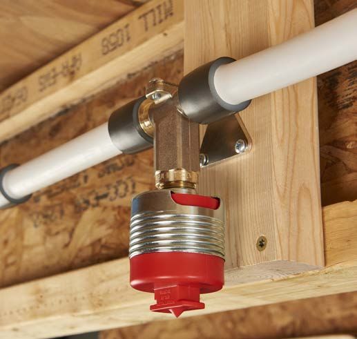
2. DESIGN & APPLICATIONS
    2.1 Applications                                                            2.2 Types of Fire Sprinkler Systems
    The FIREPEX residential fire sprinkler system serves the requirements       The NFPA 13D standard categorizes all fire sprinkler systems within
    for fire sprinkler systems as defined by National Fire Protection           two general types: wet pipe systems and dry pipe systems.
    Association (NFPA) Standard 13D Installation of Sprinkler Systems in        - Wet pipe systems are filled with water and installed in areas not
    One- and Two-Family Dwellings and Manufactured Homes and the                  subject to freezing.
    International Residential Code Section (IRC) P2904.                         - Dry pipe systems are not filled with water, and can be located in
                                                                                  unheated areas subject to freezing.
    The purpose of NFPA 13D and IRC P2904 is to provide a sprinkler
    system that aids in the detection and control of residential fires, thus    The FIREPEX system is for wet pipe systems only.
    offering improved protection against injury and loss of life. A sprinkler   Within the wet pipe systems, NFPA 13D defines the layout of systems
    system that is designed and installed in accordance with this standard      under the following types, for which the FIREPEX system can be
    is expected to prevent flashover (total involvement of the fire) in the     installed:
    room of fire origin, where sprinklered, and to improve the chance for       - Multipurpose Sprinkler System
    occupants to escape or be evacuated.                                        - Passive Purge Sprinkler System
                                                                                - Stand-alone Sprinkler System
    RAUPEX white UV shield pipe and EVERLOC+ fittings are approved
    for use in residential fire sprinkler systems as defined by NFPA 13D
    and IRC P2904 for a variety of residential applications including single-   2.2.1 Multipurpose Sprinkler Systems
    or two-family homes, town homes, modular homes and manufactured             Multipurpose systems are defined in NFPA 13D and IRC P2904 as a
    housing.                                                                    piping system intended to serve both fire sprinklers and domestic
                                                                                plumbing needs. A multipurpose system integrates the piping
                                                                                connected to a water supply with sprinklers that automatically
                                                                                discharge water over a fire area. All piping in a multipurpose system
                                                                                supplying sprinklers must be listed or conform to the piping specifica-
                                                                                tions in NFPA 13D or IRC P2904.

                                                                                                                                                                   To Domestic Hot Water

                                                                                                          Fire Sprinkler
                                                                                                                                                          T/P Relief Valve

                                                                                                                                                                                    Water Heater
                                                                                 Domestic                                           Domestic
                                                                                 Fixture                                            Fixture
                                                                                                       Fire Sprinkler
                                                                                            Domestic
                                                                                            Fixture

    Fig. 2.1: FIREPEX installation

                                                                                                                           Domestic Hot Water              Water Meter
                                                                                                                           Domestic Cold Water
                                                                                                                           Fixtures
                                                                                                                           Service Line
                                                                                                                           Fire Protection

                                                                                                                                                 City Water Main

                                                                                Fig. 2.2: Multipurpose system

4
2.2.2 Passive Purge Sprinkler System                                                                           2.3 Piping Configurations
A passive purge system is defined in NFPA 13D as a type of sprinkler                                           The NFPA 13D standard defines three types of piping systems that
system that serves a single toilet in addition to the sprinkler system.                                        are allowed to be used in residential occupancies stating that piping
                                                                                                               configurations shall be permitted to be gridded, looped or straight-
                                                                         To Domestic Hot Water
                                                                                                               run, or to be combinations thereof.

                                                                                                               Of the three aforementioned configurations:
                          Fire Sprinkler
                                                              T/P Relief Valve
                                                                                                               - Gridded systems provide the highest level of hydraulic
 Single
                                                                                           Water Heater          characteristics for pressure/flow calculations.
 Toilet
                      Fire Sprinkler                                                                           - Looped systems provide hydraulic characteristics better than
                                                                                                                 straight-run systems, but not as good as gridded systems.
                                                                                                               - Straight-run system provide the lowest level of hydraulic
                                                                                                 To Domestic
                                                                                                                 characteristics.
                                                                                                 Cold Water

                        Domestic Hot Water
                        Domestic Cold Water
                                                               Water Meter
                        Fixtures
                        Service Line                                                                           2.3.1 Gridded System
                        Fire Protection
                                                                                                               A gridded system is a sprinkler system connected by multiple branch
                                                     City Water Main
                                                                                                               lines. An activated sprinkler will be provided with water from both
                                                                                                               sides, while other branch lines help transfer the water.
Fig. 2.3: Passive purge system
                                                                                                                                              City Water Main

2.2.3 Stand-alone Sprinkler System
A stand-alone system is defined in NFPA 13D as a type of sprinkler
                                                                                                                       Domestic Hot Water
                                                                                                                       Domestic Cold Water
                                                                                                                       Fixtures

system where the above ground piping serves only fire sprinklers.                                                      Service Line
                                                                                                                       Fire Protection
                                                                                                                                             Water Meter

                                                                        To Domestic Hot Water                                                                   To Domestic
                                                                                                                                                                Hot Water

                                                             T/P Relief Valve

                                                                                          Water Heater

 Fire Sprinkler      Fire Sprinkler

                                             BFP

                                  Pressure Relief Valve               Water Meter                To Domestic
                  Drain & Test    (set 130 psi)                                                  Cold Water
                  Connection

                       Domestic Hot Water
                       Domestic Cold Water
                       Service Line
                       Fire Protection

                                                    City Water Main
                                                                                                               Fig. 2.5: Gridded system layout
Fig. 2.4: Stand-alone system

NOTICE
These drawings represent design intent and concept only. This
technical information is not intended to be used as final drawings or
specifications. It is provided only as an aid in designers' development
of the final specification and is not intended as a substitute for sound
judgment.

                                                                                                                                                                                       5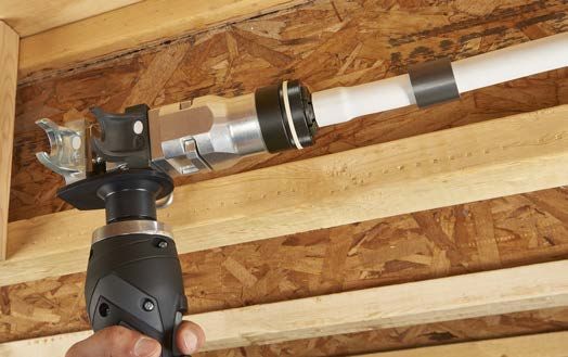
2.3.2 Looped System                                                    2.4 Design Considerations
    A looped system is a sprinkler system where multiple cross mains are   The critical points in design of an NFPA 13D and IRC P2904 sprinkler
    connected, but the branch lines are not.                               system are:
                                                                           - Identify local jurisdiction requirements, including determination of
                                     City Water Main
                                                                             pertinent building, fire protection and plumbing codes.
                                                                           - Obtain residence characteristics.
             Domestic Hot Water
             Domestic Cold Water                                           - Identify the water supply source and available flow in GPM and
             Fixtures
             Service Line
             Fire Protection
                                    Water Meter
                                                                             supply pressure in psi.
                                                                           - Identify the water supply service line including elevation difference
                                                            To Domestic
                                                            Hot Water
                                                                             between connections and routing of the service line into the
                                                                             residence.
                                                                           - Determine the specifications for the sprinklers including water flow
                                                                             and operating pressure requirements and coverage area
                                                                             specifications.
                                                                           - Lay out the piping system in the residence as a looped, gridded or
                                                                             straight-run system as defined by NFPA 13D.
                                                                           - Lay out the piping system for cold and hot water distribution.
                                                                           - Perform the hydraulic calculations on the system to determine
                                                                             system performance.
                                                                           - Coordinate fire sprinkler installation with other building trades to
                                                                             minimize installation/scheduling conflicts. Verify installation of
                                                                             sprinkler system per plan (includes sprinkler locations and proper
                                                                             mounting height).
    Fig. 2.6: Looped system layout                                         - When the fire sprinkler system connects to plumbing fixtures it is
                                                                             required to comply with prevailing local plumbing codes.

    2.3.3 Straight-run System                                              NOTICE
    A straight-run system, also known as a tree-type system, is a          The FIREPEX system shall not have a fire department connection and
    sprinkler system in which each sprinkler is served by only one water   the static pressure of the system shall be limited to 80 psi. If the static
    flow path.                                                             pressure of the water supply is not less than 80 psi, a pressure
                                                                           reducing valve set no higher than 80 psi shall be used. When a
                                      City Water Main
                                                                           pressure reducing valve is required, an automatic means of pressure
                                                                           relief shall be installed on the sprinkler system side of the pressure
                                                                           reducing valve.
              Domestic Hot Water
              Domestic Cold Water
              Fixtures
              Service Line
              Fire Protection
                                    Water Meter

                                                        To Domestic
                                                        Hot Water

    Fig. 2.7: Straight-run system layout

6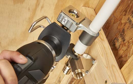
3. SYSTEM OVERVIEW
3.1 Application
The FIREPEX residential fire sprinkler system includes RAUPEX white
UV shield (PEXa) pipe, EVERLOC+ polymer and lead-free brass
fittings, PEXa compression sleeves and EVERLOC+ compression-
sleeve tools.

The EVERLOC+ compression-sleeve fitting system is a cold-
expansion PEXa fitting system available in polymer and lead-free (LF)
brass, assembled with a specially designed PEXa compression sleeve.
The fittings are designed specifically for use with RAUPEX pipe and
must only be assembled with EVERLOC+ compression-sleeve tools.
                                                                             Fig. 3.3: EVERLOC+ compression-sleeve tools

                                                                             3.2 Standards and Certifications
                                                                             RAUPEX white UV shield pipes are certified for use in residential fire
                                                                             sprinkler systems as defined by NFPA 13D or IRC P2904.

                                                                             RAUPEX red and blue UV shield are not certified for fire sprinkler
                                                                             systems.

                                                                             The FIREPEX system is third-party certified by NSF International
                                                                             (www.nsf.org) to the following standards:
                                                                             - UL 1821 Standard for Thermoplastic Sprinkler Pipe and Fittings for
                                                                               Fire Protection Service
Fig. 3.1: RAUPEX white UV shield crosslinked polyethylene (PEXa) pipe        - ASTM F877 Standard Specification for Crosslinked Polyethylene
                                                                               (PEX) Hot- and Cold-Water Distribution Systems
                                                                             - CSA B137.5 Crosslinked Polyethylene (PEX) Tubing Systems for
                                                                               Pressure Applications
                                                                             - NSF/ANSI 14 Plastic Piping System Components and Related
                                                                               Materials
                                                                             - NSF/ANSI 61 Drinking Water System Components and Related
                                                                               Materials
                                                                             - NSF/ANSI 372 Drinking Water System Components – Lead Content
                                                                               (complies with the lead-free requirements of the U.S. Safe Drinking
                                                                               Water Act)

                                                                             3.3 Warranty
                                                                             RAUPEX UV shield pipe and EVERLOC+ compression-sleeve fittings
                                                                             and sleeves are backed by a 25-year limited warranty. EVERLOC+
Fig 3.2: EVERLOC+ compression-sleeve fittings and PEXa compression sleeves   compression-sleeve tools are backed by a 2-year limited warranty.
                                                                             REHAU offers this warranty when the installation is carried out in
                                                                             accordance with the requirements outlined in the REHAU PEXa
                                                                             Warranty 855.018, which is available as a separate document at
                                                                             www.na.rehau.com/warranties.

                                                                                                                                                      7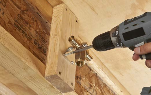
4. RAUPEX PEXa PIPE
    4.1 Pipe Properties                                                             Specification         English                    SI             Standard
    Crosslinked polyethylene is polyethylene (PE) which has undergone a            Tensile          4194-4355 psi         26-30 N/mm2
    change in molecular structure whereby the polymer chains are                   Strength         @68˚F                 @20˚C
                                                                                                    2610-2900 psi         18-20 N/mm2                   --
    chemically linked, crosslinked (X), with each other to form a three-                            @176˚F                @80˚C
    dimensional network. The result is a flexible thermoset polymer with                            per ASTM D638         per ASTM D638
    improved mechanical, thermal and chemical properties.                          IZOD Impact      No Break              No Break                      --
                                                                                   Resistance

    There are three methods of manufacturing PEX:                                  Roughness        e=0.00028 in.         e =0.007 mm                   --
    - The peroxide method (PEXa), ASTM requires a minimum of 70%                   Temperature      -40 to 200˚F          -40 to 93˚C                   --
                                                                                   Working Range
      crosslinking
                                                                                   Maximum          150 psig @ 210˚F      1035 kPa @ 99˚C          ASTM F876
    - The silane method (PEXb), ASTM requires a minimum of 65%                     Short-term       (48 hr)               (48 hr)
      crosslinking                                                                 Exposure
    - The radiation method (PEXc), ASTM requires a minimum of 65%                  UV Resistance                    See TB218                      ASTM 2657
      crosslinking

    RAUPEX pipe is manufactured using the peroxide method (PEXa),                 4.2 Pipe Dimensions and Weights
    which yields the highest, most consistent level of crosslinking. PEXa         RAUPEX white UV shield pipe for residential fire sprinkler systems is
    technology enhances flexibility and thermal memory, providing ease of         available in nominal sizes ranging from 3/4 to 2 in., and is in accor-
    handling and kink repair compared to PEXb and PEXc.                           dance to the dimensional standards defined in ASTM F876 and CSA
                                                                                  B137.5. RAUPEX is copper tube size (CTS) outside diameter (OD),
    PEXa has distinct advantages over other polymer and metal pipes:              which means that the actual OD of the pipe is 1/8 in (3.18 mm) larger
    - Resists pitting and stress corrosion                                        than the nominal size.
    - Resists scaling and deposit build-up when used with both hard and
      softened water                                                              Wall thickness is defined by the standard dimensional ratio (SDR).
    - Minimizes noise that is transmitted through pipes                           RAUPEX UV shield pipe is SDR9, which equates to the outside
    - Resists notching and abrasion damage                                        diameter being approximately nine times the wall thickness. Since
                                                                                  PEX pipe has a thicker wall than copper tube, the inside diameter (ID)
    RAUPEX is manufactured by REHAU in a facility whose quality                   is slightly smaller. However, since PEX pipe is not susceptible to the
    management system is ISO 9001 certified. In addition, RAUPEX                  erosion and corrosion issues of copper tube, systems can be designed
    production is independently monitored annually by NSF International,          at higher velocities which allow for comparable sizing of a system.
    CSA Group and Underwriters Laboratories Inc. (UL).
                                                                                  Table 4.2: RAUPEX White UV Shield Pipe Dimensions and Weights
    Table 4.1: RAUPEX Properties                                                    Pipe Size       Average OD         Min Wall Thickness       Weight
      Specification          English                    SI         Standard                           in (mm)               in (mm)           lb/ft (kg/m)

     Minimum          58 lb/ft3                 926 kg/m3       ASTM F876          3/4 in           0.875 (22.22)         0.097 (2.47)            0.10 (0.15)
     Density                                                                       1 in             1.125 (28.58)         0.125 (3.18)            0.17 (0.26)
     Minimum          70%                       70%             ASTM F876          1 1/4 in         1.375 (34.92)         0.153 (3.88)        0.25 (0.37)
     Degree of
                                                                                   1 1/2 in         1.625 (41.28)         0.181 (4.59)        0.35 (0.52)
     Crosslinking
                                                                                   2 in             2.125 (53.98)         0.236 (6.00)        0.60 (0.90)
     Max Thermal      2.84 Btu in/(ft2 ˚F•hr)   0.41 W/(m˚K)    DIN 16892
     Conductivity
     Coefficient of   9.33 x 10⁻⁴ in/ft ˚F      0.14 mm/(m˚C)   Mean @
     Linear           @68˚F                     @20˚C           20-70˚C per DIN   4.3 Pipe Markings
     Expansion        1.33 x 10⁻³ in/ft ˚F      0.2 mm/(m˚C)    16892
                      @212˚F                    @100˚C                            RAUPEX pipe markings are repeated every 3 ft (0.9 m), list all
                                                                                  certifications and approvals, and include an incremental footage
     Modulus of       87,000-130,500 psi        600-900 N/mm2   Minimum @         marking to assist with installation.
     Elasticity       @ 68˚F                    @20˚C           20˚C per DIN
                      43,500-58,000 psi         300-400 N/mm2   16892
                      @176˚F                    @80˚C

8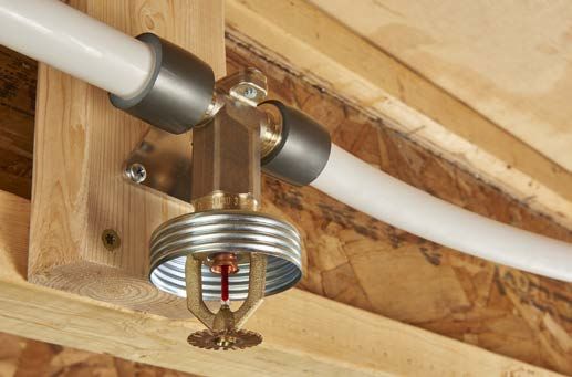
4.3.1 PEX Designation Code                                                                    4.5 Excessive Temperature and Pressure Capability
RAUPEX pipe is further identified with a PEX Material Designation                             Temperature and pressure (T&P) relief valves are safety mechanisms
code in accordance to ASTM F876. The PEX Designation Code is the                              in case the system overheats (mandatory in hot water distribution
abbreviation for the material - PEX - followed by four numerals.                              systems). These valves act quickly to relieve excess temperature or
                                                                                              pressure if either one of these conditions is reached. In the event of a
The PEX Designation Code for RAUPEX white UV shield pipe is                                   water heating system failure or T&P relief valve failure, RAUPEX pipe
                                                                                              has been tested to accommodate short-term exposure conditions of
   PEX 3306
                                                                                              210°F (99°C) at 150 psi (10 bar) for 48 hours.

The first numeral (3) refers to the chlorine resistance in one of four
categories, when tested in accordance with ASTM Test Method F2023                             NOTICE
and evaluated in accordance with ASTM F876. This measurement                                  Failure to follow pressure and temperature limits may damage the pipe
indicates the allowable hours of 140°F water recirculation in 1 day.                          resulting in leaks and operational failures, and will negate any
                      1 = 4 hours            3 = 12 hours            5 = 24 hours             warranty provided by REHAU for RAUPEX pipes. The designer must
    0 = none                                                                                  incorporate proper controls into the system to ensure the pressure and
                     e.g., 25% of lifetime   e.g., 50% of lifetime   e.g., 100% of lifetime
                                                                                              temperature capability of the pipe is not exceeded.

The second numeral (3) refers to UV resistance in one of four
categories, when tested in accordance with ASTM Test Method F2657                             4.6 Corrosion Resistance
and evaluated in accordance with ASTM F876. The measurement                                   RAUPEX pipe is non-reactive and displays excellent corrosion
indicates the allowable time pipe can be exposed to UV without being                          resistance. Corrosion is a process that requires electrically conductive
compromised.                                                                                  materials and occurs on metals. PEXa, being a dielectric, does not
                                                                                              corrode like metal pipes. PEXa also resists the buildup of scale which
    0 = none         1 = 1 month             2 = 3 months            3 = 6 months
                                                                                              is common with copper pipe.

The third and fourth numerals (06) refer to the Hydrostatic Design                            4.7 Chlorine Resistance
Stress for water at 73°F in hundreds of psi. The standard pressure                            RAUPEX pipe has been tested in accordance with ASTM F2023,
rating at 73°F is derived from this measurement.                                              Standard Test Method for Evaluating the Oxidative Resistance of
                                                                                              Crosslinked Polyethylene (PEX) Tubing and Systems to Hot Chlorinated
                                  06 = 630 psi
                                                                                              Water as required in ASTM F876. RAUPEX pipe exceeds the minimum
                                                                                              extrapolated test lifetime as certified by NSF for cold water applica-
                                                                                              tions, intermittent hot water applications and timed hot water
4.4 Pressure and Temperature Ratings                                                          applications.
The maximum temperature and pressure ratings of RAUPEX pipe are
in accordance to ASTM F876, CSA B137.5 and PPI TR-3. The                                      This recommendation applies to RAUPEX white UV shield pipes for
designer shall determine the actual conditions and apply the appropri-                        cold water and intermittent hot water applications (25% @ 140°F,
ate and additional design factors as required for any particular project.                     75% @ 73°F) and for timed hot water recirculation systems for up to
                                                                                              12 hours per day (50% @ 140°F, 50% @ 73°F). The ASTM F876
According to the REHAU PEXa Limited Warranty, the RAUPEX pipe                                 standard includes designation codes for these applications which are
warranty period is for operating conditions at or below 180°F (82.2°C)                        included on the print line of RAUPEX pipes.
in permitted applications when the handling, use, installation and
maintenance continually complies with all REHAU Technical
Guidelines.                                                                                   4.8 Ultraviolet Resistance
                                                                                              All polymers are susceptible to damage from exposure to the
Table 4.3: RAUPEX White UV Shield Pressure and Temperature Ratings                            ultraviolet (UV) radiation in sunlight. PEX pipes can be designed to
 RAUPEX White UV Shield Pipe                                                                  protect against short-term UV damage, but after some time, UV
 Maximum Pressures and Temperatures            Design Factors                                 radiation will reduce the lifetime of the pipe. The extent of the
 160 psi @ 73.4°F (1055 kPa @ 23°C)            0.50 (per ASTM F876, CSA B137.5)               reduction depends on factors such as temperature, pressure and
 130 psi @ 120°F (900 kPa @ 49°C)              0.50 (per ASTM F876, CSA B137.5)               chlorination levels in potable water. Excessive UV exposure will reduce
 100 psi @ 180°F (690 kPa @ 82.2°C)            0.50 (per ASTM F876, CSA B137.5)               the lifetime of the PEXa pipe.

                                                                                                                                                                         9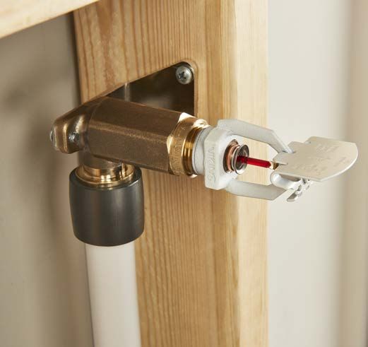
REHAU has performed extensive testing of RAUPEX pipes exposed to          4.10 Chemical Compatibility
     UV, leading to the maximum UV exposure times expressed in                 While RAUPEX pipes are resistant to many chemicals that are used in
     accumulated days. Once the pipes leave the manufacturing plant, any       typical residential fire sprinkler applications, there are some chemicals
     exposure to UV, including transportation and storage, is part of the      that may damage the pipe.
     accumulated exposure time.
                                                                               Chemicals that may be damaging include (but are not limited to):
     Although ASTM F876 only categorizes up to 6 months of UV resis-           - Adhesives
     tance (Material Designation Code = 3306), REHAU has tested and            - Oil or petroleum-based products
     certified RAUPEX white UV shield pipe according to ASTM F2657 for         - Paints
     the following maximum UV exposure period:                                 - Solvents
                                                                               - Oxidizing agents
     - RAUPEX white UV shield pipe: Maximum exposure time of one year          - Disinfectants
       accumulated                                                             - PVC glues
                                                                               - Solvents and cements
     RAUPEX pipes must be kept in the original packaging until the time of
     installation. RAUPEX must not be stored outdoors and is not designed      Many factors, such as exposure time, temperature, pressure and other
     for permanent outdoor exposure (with the exception of non-exposed         operating parameters, can influence the performance of a pipe that is
     buried applications).                                                     exposed to a chemical. To determine the impact of a particular
                                                                               chemical, short- and long-term pressure testing may be required. In
                                                                               some cases, a pipe may be resistant to short-term exposure to the
     NOTICE                                                                    chemical, but not resistant to continuous exposure. Each chemical
     Failure to follow maximum UV exposure limits may damage the pipe          must be evaluated individually. It is the responsibility of the installing
     resulting in leaks and operational failures, and will negate any          contractor to verify chemical compatibility of any chemicals that may
     warranty provided by REHAU for RAUPEX pipes.                              come into contat with the polymer material.

     4.9 Bend Radius                                                           4.11 Freeze Break Resistance
     RAUPEX pipe may be bent, even when cold. REHAU support bends              The flexibility of the RAUPEX pipe allows it to expand as water freezes
     can assist to create tight bends without kinking. The typical bend        in the pipe as long as the pipe has room to expand. When the water
     radius used by the installer is 8X the OD. The minimum bend radius is     thaws, the pipe returns to its original shape. If the pipe is not allowed
     5X the OD for cold bends. For an even smaller bend radius, the pipe       to expand (e.g., it is encased in concrete), it may burst.
     may be heated with a heat gun and bent to no less than 3X the OD. If
     a tighter bend radius is required, the designer should consider using a
     smaller diameter pipe.                                                    NOTICE
                                                                               Designers and installers must take precautions as per the guidelines
     Table 4.4: RAUPEX Bend Radius                                             defined in NFPA 13D to ensure that pipes do not freeze. Frozen pipes
                                   Bend Radius in (mm)                         may burst resulting in leaks and operational failures.
       Pipe Size    Typical 8X OD        Min. Cold 5X OD   Min. Heated 3X OD
         3/4 in        7.0 (178)           4.375 (111)        2.625 (67)
          1 in         9.0 (229)           5.625 (143)        3.375 (86)
        1 1/4 in      11.0 (279)           6.875 (175)        4.125 (105)
                                                                               4.12 Condensation
        1 1/2 in      13.0 (330)               --                 --
                                                                               Condensation occurs on pipes when the surface temperature is lower
                                                                               than the dew point of the environment. This is typically a problem for
          2 in        17.0 (432)               --                 --
                                                                               metallic cold water piping. PEX pipe has lower thermal conductivity
                                                                               (0.41 W/m°K) than copper (401 W/m°K) resulting in less heat loss to
                                                                               the surface and greater resistance to condensation or sweating.

10
5. EVERLOC+ COMPRESSION-SLEEVE FITTINGS
5.1 Fitting Scope 5.1.2 Fitting and Sleeve Markings
The EVERLOC+ compression-sleeve system is a cold-expansion PEXa All polymer fittings include the following marks for identification
fitting system that is available in polymer and lead-free (LF) brass and
is assembled with a specially designed PEXa compression sleeve. The
fitting is designed specifically for use with RAUPEX pipe and must OR
only be assembled with the EVERLOC+ compression-sleeve tools.
EVERLOC+ fittings for residential fire sprinkler applications are
available in 3/4 to 2 in. sizes and are listed for use with RAUPEX white
UV shield pipe (3/4 to 2 in.) manufactured in accordance with ASTM
F876.
For a detailed description of the REHAU system components, refer to
the REHAU Building Solutions Product Catalog (855.312).
5.1.1 Fitting Features Fig. 5.2: Fitting size marking (e.g., 3/4”)
EVERLOC+ polymer and lead-free (LF) brass fittings have the
following features:
1. Four sealing edges
2. Pipe stop
3. Fitting collar
4. Tool jaw body
1
3
Fig. 5.3: Batch code (e.g., production date)
All LF brass fittings are marked "REHAU"
All sleeves include the following
marks for identification
- Sleeve size (e.g., 3/4")
4 - Batch code for production date
2 Fig. 5.4: Sleeve markings
Fig. 5.1: EVERLOC+ fitting features
115.1.3 Polymer Fittings
EVERLOC+ polymer fittings are available in couplings, tees, elbows,
multi-port tees and plugs. All polymer fittings are produced from a
polyphenylsulfone (PPSU) material. See also REHAU Technical Bulletin
TB265 EVERLOC+ Polymer Fitting Material - PPSU.
5.1.4 Lead Free (LF) Brass Fittings
EVERLOC+ LF brass fittings are available as couplings, tees, elbows,
plugs and transition fittings to NPT thread and copper solder
connections. All metal fittings are produced from ECO BRASS® (UNS Fig. 5.6: EVERLOC+ PEXa compression sleeves
69300 or CW 724R). See also REHAU Technical Bulletin TB264
EVERLOC+ Lead-free Brass Fitting Material.
5.1.6 Certifications
The EVERLOC+ compression-sleeve fitting system is certified to the
following standards:
- UL 1821 Standard for Thermoplastic Sprinkler Pipe and Fittings for
Fire Protection Service
- ASTM F877, Standard Specification for Crosslinked Polyethylene
(PEX) Hot- and Cold-Water Distribution Systems
- NSF/ANSI 14, Plastic Piping System Components and Related
Materials
- NSF/ANSI 61, Drinking Water System Components – Health Effects
- NSF/ANSI 372, Drinking Water System Components – Lead Content
- CSA B137.5, Crosslinked polyethylene (PEX) Tubing Systems for
Pressure Applications
Fig. 5.5: EVERLOC+ polymer and LF brass fittings
5.1.5 PEXa Compression Sleeves
EVERLOC+ compression sleeves are produced using a specially
formulated PEXa material and are designed specifically for use with
EVERLOC+ fittings and RAUPEX pipe. EVERLOC+ compression
sleeves have the following features:
- Co-extruded platinum-colored PE coating
- Squarely cut ends that can be slid over the pipe in either direction
- Grooved and roughened inside surface for locking the sleeve into
place once slid over the pipe and fitting
125.1.7 Equivalent Length of Fittings Adapters (PEX to MPT/FPT)
It is common practice for designers to convert the pressure drop Equivalent
across fittings to an average equivalent length of pipe. These Fitting Description Length (ft)
equivalent lengths are added to the total pipe length. Designers can 3/4 x 3/4 in. FPT EVERLOC+ LF Brass Adapter 2.8
calculate total pressure loss using this adjusted piping system length. 3/4 x 3/4 in. MPT EVERLOC+ LF Brass Adapter 3.4
3/4 x 1 in. MPT EVERLOC+ LF Brass Adapter 4.3
Table 5.1: Equivalent Length of Fittings 1 x 1 in. FPT EVERLOC+ LF Brass Adapter 3.6
Couplings 1 x 1 in. MPT EVERLOC+ LF Brass Adapter 3.8
Fitting Description Equivalent Length (ft) 1 1/4 x 1 1/4 in. MPT EVERLOC+ LF Brass Adapter 4.9
3/4 x 3/4 in. EVERLOC+ Polymer Coupling 0.8 1 1/2 x 1 1/2 in. MPT EVERLOC+ LF Brass Adapter 5.9
1 x 3/4 in. EVERLOC+ Polymer Coupling 2.7 2 x 2 in. MPT EVERLOC+ LF Brass Adapter 7.3
1 x 1 in. EVERLOC+ Polymer Coupling 1.1
1 1/4 x 1 in. EVERLOC+ Polymer Coupling 4.0
1 1/4 x 1 1/4 in. EVERLOC+ Polymer Coupling 2.0
Tees
Equivalent Equivalent
1 1/2 x 1 in. EVERLOC+ Polymer Coupling 4.8
Length (ft) Length (ft)
1 1/2 x 1 1/2 in. EVERLOC+ Polymer Coupling 2.0 Fitting Description RUN BRANCH
2 x 1 in. EVERLOC+ LF Brass Coupling 5.2 3/4 x 3/4 x 3/4 in. EVERLOC+ Polymer Tee 1.2 7.6
2 x 1 1/4 in. EVERLOC+ LF Brass Coupling 5.3 3/4 x 3/4 x 1 in. EVERLOC+ Polymer Tee - 6.8
2 x 1 1/2 in. EVERLOC+ LF Brass Coupling 6.1 1 x 1 x 1/2 in. EVERLOC+ Polymer Tee 1.6 3.9
2 x 2 in. EVERLOC+ Polymer Coupling 2.2 1 x 3/4 x 3/4 in. EVERLOC+ Polymer Tee 2.8 6.5
1 x 3/4 x 1 in. EVERLOC+ Polymer Tee 3.1 10.9
Elbows (PEX to PEX) 1 x 1 x 3/4 in. EVERLOC+ Polymer Tee 1.2 6.7
Fitting Description Equivalent Length (ft) 1 x 1 x 1 in. EVERLOC+ Polymer Tee 1.6 10.6
3/4 x 3/4 in. EVERLOC+ Polymer Elbow 7.0 1 1/4 x 1 x 1 in. EVERLOC+ Polymer Tee 3.8 9.7
1 x 1 in. EVERLOC+ Polymer Elbow 10.7 1 1/4 x 1 x 1 1/4 in. EVERLOC+ LF Brass Tee 4.3 9.6
1 1/4 x 1 1/4 in. EVERLOC+ Polymer Elbow 14.2 1 1/4 x 1 1/4 x 1 in. EVERLOC+ Polymer Tee 2.3 10.1
1 1/2 x 1 1/2 in. EVERLOC+ Polymer Elbow 16.0 1 1/4 x 1 1/4 x 1 1/4 in. EVERLOC+ Polymer Tee 2.2 14.4
2 x 2 in. EVERLOC+ Polymer Elbow 24.2 1 1/2 x 1 x 1 in. EVERLOC+ LF Brass Tee 5.5 7.9
1 1/2 x 1 x 1 1/2 in. EVERLOC+ LF Brass Tee 5.6 12.4
1 1/2 x 1 1/4 x 1 in. EVERLOC+ LF Brass Tee 4.4 8.1
Elbows (PEX to transition)
1 1/2 x 1 1/4 x 1 1/4 in. EVERLOC+ LF Brass Tee 4.5 9.5
Equivalent
1 1/2 x 1 1/4 x 1 1/2 in. EVERLOC+ LF Brass Tee 4.3 10.9
Fitting Description Length (ft)
1 1/2 x 1 1/2 x 1 in. EVERLOC+ Polymer Tee 2.2 9.1
3/4 x 3/4 in. C Female EVERLOC+ LF Brass Elbow 7.1
1 1 2 x 1 1/2 x 1 1/4 in. EVERLOC+ LF Brass Tee 1.7 9.6
3/4 x 3/4 in. C Male EVERLOC+ LF Brass Elbow 7.4
1 1/2 x 1 1/2 x 1 1/2 in. EVERLOC+ Polymer Tee 2.6 17.0
3/4 x 3/4 in. MPT EVERLOC+ LF Brass Drop Ear Elbow 7.5
2 x 1 1/4 x 2 in. EVERLOC+ LF Brass Tee 6.7 14.9
2 x 1 1/2 x 1 in. EVERLOC+ LF Brass Tee 6.2 7.7
Adapters (PEX to copper) 2 x 1 1/2 x 1 1/4 in. EVERLOC+ LF Brass Tee 6.3 9.5
Equivalent 2 x 1 1/2 x 1 1/2 in. EVERLOC+ LF Brass Tee 6.4 11.2
Fitting Description Length (ft) 2 x 1 1/2 x 2 in. EVERLOC+ LF Brass Tee 6.5 14.6
3/4 x 1 in. C Female EVERLOC+ LF Brass Adapter 3.9 2 x 2 x 1 in. EVERLOC+ Polymer Tee 3.2 9.0
3/4 x 3/4 in. C Female EVERLOC+ LF Brass Adapter 2.7 2 x 2 x 1 1/4 in. EVERLOC+ LF Brass Tee 1.9 9.7
3/4 x 3/4 in. C Male EVERLOC+ LF Brass Adapter 2.6 2 x 2 x 1 1/2 in. EVERLOC+ LF Brass Tee 1.9 10.9
1 x 1 in. C Female EVERLOC+ LF Brass Adapter 3.5 2 x 2 x 2 in. EVERLOC+ Polymer Tee 4.0 25.3
1 x 1 in. C Male EVERLOC+ LF Brass Adapter 3.3
1 1/4 x 1 1/4 in. C Female EVERLOC+ LF Brass Adapter 4.1
1 1/4 x 1 1/4 in. C Male EVERLOC+ LF Brass Adapter 4.3
1 1/2 x 1 1/2 in. C Female EVERLOC+ LF Brass Adapter 5.3
1 1/2 x 1 1/2 in. C Male EVERLOC+ LF Brass Adapter 5.4
2 x 2 in. C Female EVERLOC+ LF Brass Adapter 7.0
2 x 2 in. C Male EVERLOC+ LF Brass Adapter 6.9
135.2 Fitting Assembly Required assembly tools include:
Before starting the installation process, read the EVERLOC+ - RAUPEX cutter
Compression-sleeve System Product Instructions (855.724). - EVERLOC+ compression-sleeve tools
- EVERLOC+ expander heads and compression jaws
Assembling the EVERLOC+ compression-sleeve system requires the
use of the EVERLOC+ compression-sleeve tools. Only make
EVERLOC+ compression-sleeve joints with these tools. Refer to 5.3 Installation Considerations
EVERLOC+ Power Tool Product Instruction Manual (855.725), Some precautions and additional considerations that should be taken
EVERLOC+ XL Power Tool Product Instruction Manual (855.728) and when installing the system.
EVERLOC+ XL Expander Tool Product Instruction Manual (855.729) for
a complete understanding of operation, care and use of the
EVERLOC+ compression-sleeve tools. 5.3.1 EVERLOC+ Fitting Removal
- EVERLOC+ LF brass fittings CAN be reused, as long the rib area
was not damaged during removal.
WARNING - EVERLOC+ polymer fittings CANNOT be reused and should be
Read the instruction manual for the EVERLOC+ discarded immediately.
compression-sleeve tools before use and follow all - EVERLOC+ compression sleeves CANNOT be reused and should be
safety precautions - improper use can cause serious
discarded immediately.
personal injury.
WARNING
To reduce the risk of permanent eye injury, always
wear close-fitting protective eye wear with side
protection. Eye wear must be impact-rated and
marked as complying with ANSI Z87.
NOTICE
Use only EVERLOC+ compression-sleeve tools for assembly and Fig. 5.7: DO NOT cut the EVERLOC+ compression sleeve from finished joint
installation. Use of other tools will result in an improperly assembled
joint, which may result in leaks and property damage.
The basic process of assembling an EVERLOC+ compression-sleeve
joint is as follows:
- Make a clean, square cut of the RAUPEX pipe using a RAUPEX
cutter
- Slide the EVERLOC+ compression sleeve over the RAUPEX pipe
ensuring the sleeve is a minimum of two times the length of the
sleeve from the end of the cut pipe to allow for expansion of the pipe
only Fig. 5.8: DO NOT cut RAUPEX pipe from fitting
- Expand the RAUPEX pipe twice, ensuring the expander head is
rotated 1/2 of one expander head segment between expansions,
using the EVERLOC+ compression-sleeve tools 5.3.1.1 Fitting Removal of Completed Joint (LF brass ONLY)
- Insert the EVERLOC+ compression-sleeve fitting into the expanded If it is required to remove the LF brass fitting or disassemble the LF
end of the RAUPEX pipe so that the pipe is touching the pipe stop on brass compression-sleeve joint, use the following procedure:
the fitting
- Compress the EVERLOC+ compression sleeve over the RAUPEX pipe If the fitting has been inserted into the pipe and the sleeve has been
and EVERLOC+ compression-sleeve fitting using the EVERLOC+ compressed, safely hold the fitting while it is heated. Be careful not to
compression-sleeve tools damage the fitting with the tool.
1. Heat the sleeve directly using a heat gun.
2. Rotate the joint several times while heating.
3. Remove heat and use pliers to pull the sleeve off the fitting, then
immediately pull the fitting out of the pipe.
14WARNING 5.3.2 Protecting EVERLOC+ Joints
- Do not use open flames to disassemble the joint. Open flames can REHAU permits EVERLOC+ compression-sleeve joints (polymer and
cause injury or property damage. LF brass) to be buried or concealed. REHAU recommends that
- Never use a torch, open flame or heat gun on a pressurized system. threaded connections never be buried or concealed as they must be
- Never rework a connection that is under pressure. Depressurize the accessible for periodic inspection, per prevailing local codes.
system, cut out connection and replace.
The requirement to wrap an EVERLOC+ joint can depend on many
factors including location and the presence of other materials that
contact or can come in contact with the joint.
When wrapping an EVERLOC+ joint, the following is required:
- Wrap the joint, ensure minimum of 50% overlap of the tape
- Avoid wrinkles or kinks in the tape and ensure the joint is completely
covered, extending on to the pipe as necessary
- Indicate the location of each joint as required on the “as-built”
Fig. 5.9: Heating EVERLOC+ compression sleeve with heat gun drawings
Fig. 5.12: REHAU Protective Tape, Red Fig. 5.13: Linerless Rubber Tape, Black
Fig. 5.10: Removing pipe from LF brass fitting
Note: Use only REHAU recommended protective tapes referenced in
For re-assembly of a joint, the following should be considered: REHAU Technical Bulletin TB266 Protecting EVERLOC+ Joints. Do not
- The end of the pipe where the previous fitting had been installed use other types of tapes (e.g., duct tape, standard electrical tape) to
must be completely cut off prior to making a new joint. Cutting off a wrap the joint, as chemicals in the adhesive may not be compatible
minimum of 3 in (approximately 75 mm) is recommended. with the PPSU fitting material or the PEXa pipe.
Note: Never use heat shrink tubing (e.g., RAUCROSS) to wrap the
joint, as the high temperatures produced from a heat gun will soften
the pipe and may cause it to pull away from the fitting.
Fig. 5.11: Cut off 3 in. of pipe from end prior to making new joint
5.3.1.2 Fitting Removal of Partially Completed Joint (LF Brass
ONLY)
If the fitting has been inserted into the pipe, but the sleeve has not Fig. 5.14: DO NOT use heat shrink tubing for EVERLOC+ joints
been compressed, attempt to remove it without damaging the fitting.
If fitting cannot be easily removed, heat 1 to 1 1/2 in (25 to 38 mm) of
the pipe that covers the fitting and pull the fitting out of the pipe. 5.3.2.1 Concealed in Inaccessible Locations
When EVERLOC+ joints are concealed but are still in open air spaces
(e.g., behind drywall), it is not necessary to wrap the joint. However,
the installer should ensure that the fitting does not come in contact
with chemicals (e.g., PVC glues, solvents and cements) that could
damage the fitting material.
155.3.2.2 Buried Directly in Concrete Slab: 5.3.7 Chlorine Resistance
When burying an EVERLOC+ polymer joint directly in a concrete slab, EVERLOC+ compression-sleeve joints have a chlorine resistance
it is not necessary to wrap the joint. However, there are some additives rating based on the ratings of RAUPEX pipe, as defined in Section 4.7.
in concrete that could potentially damage the fitting material, and in
this case, wrapping is recommended. EVERLOC+ LF brass fittings
buried directly in a concrete slab must be wrapped. 5.3.8 Stress Corrosion Resistance
EVERLOC+ LF brass fittings have been tested in accordance with
UL1821 and NSF/ANSI 14 and comply with the requirement for stress
5.3.2.3 Buried in a Sub-base or Underground in Soil: corrosion resistance. However, fittings should not be exposed to
In these instances, the joint must be wrapped. harmful chemicals or aggressive water conditions that could result in
operational failures.
5.3.2.4 With Foaming Agents:
Foaming agents and solvents in closed-cell foam insulation kits can 5.3.9 Chemical Compatibility
damage the PPSU fitting material. Therefore, it is necessary to wrap There are certain chemicals that can damage the EVERLOC+
polymer fittings in a protective tape to protect from polyurethane compression-sleeve system. This applies to external exposure of
foams. chemicals and to the transport of such chemicals by the piping
system.
Chemicals that may damage the compression-sleeve system include
5.3.3 Pressure Testing (but are not limited to):
The compression-sleeve joint is ready for immediate pressure testing - Adhesives and tapes other than those recommended by REHAU
and use after completion of the assembly process. There is no wait - Oil/petroleum-based products
time for the system to be put into service. See Section 7.4 for REHAU - Paints, solvents
pressure test procedures. - Oxidizing agents (e.g., bleach)
- Disinfectants (e.g., separate dosing unit integrated into building
distribution system)
5.3.4 Pressure and Temperature Ratings - PVC glues, solvents and cements
The maximum temperature and pressure ratings of the REHAU
residential fire sprinkler system are in accordance with NFP 13D,
ASTM F877 and CSA B137.5 for SDR9 PEX, as defined in
Section 4.4.
5.3.5 Ultraviolet Resistance
The fittings and sleeves must never be stored in areas exposed to
direct UV light or stored outside of the original cardboard packaging.
In addition, the system is not intended for permanent outdoor
applications or in areas with continuous UV exposure. Fig. 5.15: DO NOT use harmful chemicals near EVERLOC+ fittings
Many factors, such as exposure time, temperature, pressure and
5.3.6 Freeze Break Resistance other operating parameters, can influence the performance of a
The flexibility of RAUPEX pipe allows it to expand as water freezes in system that is exposed to a chemical. To determine the impact of a
the pipe as long as the pipe has room to expand. When the water particular chemical, short- and long-term pressure testing may be
thaws, the pipe returns to its original shape. However, this flexibility required. In some cases, a system may be resistant to short-term
does not ensure the integrity of the joint. If the pipe is not allowed to exposure to the chemical, but not resistant to continuous exposure.
expand (e.g., it is encased in concrete), it may burst. Each chemical must be evaluated individually. It is the responsibility of
the installing contractor to verify chemical compatibility of any
chemicals that may come into contact with the polymer material.
NOTICE
Designers and installers must take precautions as per the guidelines
defined in NFPA 13D to ensure that pipes do not freeze. Frozen pipes
may burst resulting in leaks and operational failures.
165.3.10 Copper Soldering NOTICE
Proper soldering techniques must be followed when soldering all Use only EVERLOC+ compression-sleeve tools for assembly and
compression-sleeve fittings according to the Copper Development installation. Use of other tools will result in an improperly assembled
Association (CDA) Handbook: joint, which may result in leaks and property damage.
- The surface of the fitting soldering area must be properly cleaned for
a good solder connection. Applying flux is not considered sufficient 5.4.1 EVERLOC+ Power Tool
cleaning for the soldering area. Using a proper sanding or brush For assembly of EVERLOC+ fittings up to 1 in. Use the
technique is necessary to remove the surface oxides. In order to EVERLOC+ power tool. Refer to EVERLOC+ Power Tool Product
prevent further formation of oxides, the flux should be applied Instruction Manual (855.725) for a complete understanding of
immediately after the cleaning process. A proper flux that is operation, care and use of the tool.
compatible with the brass alloy must be used.
- Care must be taken to not overheat the soldering surface as this can
lead to the formation of oxides preventing good adhesion of the
solder material. It is imperative that the fitting is heated evenly
around the entire surface so as to not overheat one particular area.
- All completed solder joints must be tested for joint integrity following
the procedures prescribed by prevailing local codes.
When soldering an LF brass EVERLOC+ fitting:
- The fitting must be soldered onto the copper first.
- The solder joint must be allowed to cool to ambient room
temperature prior to making an EVERLOC+ connection.
- Never solder after EVERLOC+ connection has been made.
Fig. 5.16: EVERLOC+ power tool
5.4 EVERLOC+ Compression-sleeve Tools
Assembling the EVERLOC+ compression-sleeve system requires the EVERLOC+ power tool standard kit:
use of the EVERLOC+ compression-sleeve tools. Only make - EVERLOC+ power tool
EVERLOC+ compression-sleeve joints with these tools. - Expansion adapter
- 1/2, 3/4 and 1 in. EVERLOC+ expander heads (quick change)
Before use, read and understand the following safety symbols which - 1/2, 3/4 and 1 in. EVERLOC+ compression jaws
are found on the EVERLOC+ compression-sleeve tools. - DEWALT® 12V Li-ion battery (DCB127) (2 batteries per kit)
- DEWALT 12V/20V Li-ion charger 120VAC (DCB107)
Safety Alert Symbol – To reduce the risk of injury, follow --DEWALT 12V/20V Li-ion Battery Charger Instruction Manual
the specified safety instructions. - Pipe cutter
- Lubricant
Read and follow all safety precautions in the instruction - Cleaning brush
manual. Improper use can lead to serious personal injury - Tool case
or property damage. --EVERLOC+ Power Tool Product Instruction Manual
To reduce the risk of serious eye injury, always wear
proper eye protection.
Risk of electric shock. Never operate the power tool in
damp or wet conditions. Never expose to rain or
submerge in water or other liquids. Never operate the
power tool near wires or cables carrying electric current.
To reduce the risk of severe personal injury, including
crush and laceration injury, keep fingers, hands and all
parts of your body away from the expander head,
hydraulic slide and compression jaws during operation.
Fig. 5.17: EVERLOC+ power tool standard kit
175.4.2 EVERLOC+ XL Power Tool 1 1/4 to 2 in. 5.4.3 EVERLOC+ XL Expander Tool 1 1/4 to 2 in.
Assembling the EVERLOC+ compression-sleeve system with In addition to the EVERLOC+ XL power tool, the EVERLOC+ XL
diameters of 1 1/4 through 2 in. requires the use of the EVERLOC+ expander tool can be used for the expansion steps of the 1 1/4 to 2 in.
XL power tool. Refer to the EVERLOC+ XL Power Tool Product fitting assembly process. Use of this tool in addition to the XL power
Instruction Manual (855.728) for a complete understanding of tool allows for greater efficiency in some installation situations. Refer
operation, care and use of the tool. to the EVERLOC+ XL Expander Tool Product Instruction Manual
(855.729) for a complete understanding of operation, care and use of
the tool.
Fig. 5.20: EVERLOC+ XL expander tool Fig. 5.21: EVERLOC+ XL expander tool
standard kit
Fig. 5.18: EVERLOC+ XL power tool EVERLOC+ XL expander tool standard kit:
- EVERLOC+ XL expander tool
EVERLOC+ XL power tool standard kit: - MAKITA 18V Li-ion battery
- EVERLOC+ XL power tool --MAKITA 18V Li-ion Battery Charger Instruction Manual
- Expansion adapter - Lubricant
- 1 1/4, 1 1/2 and 2 in. EVERLOC+ expander heads (quick change) - Cleaning brush
- 1 1/4, 1 1/2 and 2 in. EVERLOC+ compression jaws - Tool case (gray latches)
- MAKITA® 18V Li-ion battery (BL1840B) (2 batteries per kit) --EVERLOC+ XL Expander Tool Product Instruction Manual
- MAKITA 18V Li-ion charger 120VAC (DC18RC)
--MAKITA 18V Li-ion Battery Charger Instruction Manual
- Pipe cutter
- Lubricant
- Cleaning brush
- Tool case (black latches)
--EVERLOC+ XL Power Tool Product Instruction Manual
Fig. 5.19: EVERLOC+ XL power tool standard kit
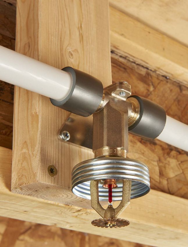
185.5 Fire Sprinklers 5.5.2 Domed Concealed Pendent Sprinklers
An automatic sprinkler is a fire suppression or control device that Domed concealed pendent sprinklers have a cover plate assem-
operates automatically when its heat-actuated element is heated to its bly that, when installed, protrudes below the ceiling. During fire
thermal rating or above. When activated, water discharges over the conditions, when the temperature around the sprinkler approaches its
specific area on fire. operating temperature, the cover plate detaches and falls away.
Only residential sprinklers that have been tested and listed for Continued heating of the now exposed sprinkler causes the
residential fire protection service may be used. The sprinklers must be sprinkler’s heat responsive element to disengage releasing the sealing
installed in accordance with their listing and limitations. assembly. This allows water to flow from the sprinkler.
NOTICE
Nothing in this manual supersedes national or local code requirements
or the recommendations of other manufacturers regarding their
components. Observe all applicable national, state and local laws,
regulations, standards, codes and ordinances. If you believe REHAU
product information conflicts with applicable code requirements,
industry standards, or the recommendations of other manufacturers
regarding their components, contact the REHAU distributor in your
area and consult with the building authority having jurisdiction before
installation. Fig 5.23: Domed concealed pendent sprinkler
There are four types of recommended sprinklers: flat plate concealed
pendent, domed concealed pendent, recessed pendent and horizontal
sidewall. WARNING
Do not paint the cover plate of the concealed sprinkler. Paint may
5.5.1 Flat Plate Concealed Pendent Sprinklers interfere with the operation of the sprinkler, preventing it from
Flat plate concealed pendent sprinklers have a cover plate that is achieving its life safety function.
installed flush to the ceiling. During fire conditions, when the tempera-
ture around the sprinkler approaches its operating temperature, the
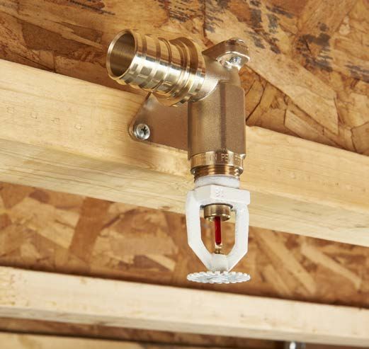
cover plate detaches and falls away. 5.5.3 Recessed Pendent Sprinklers
Recessed pendent sprinklers are visible in the ceiling and do not have
Continued heating of the now exposed sprinkler causes the sprinkler’s a cover plate. During fire conditions, continued heating
heat responsive element to disengage, releasing the sealing assembly, of the exposed sprinkler causes the heat responsive element to
allowing water to flow. disengage. This allows water to flow from the sprinkler.
Fig. 5.22: Flat plate concealed pendent sprinkler
Fig 5.24: Recessed pendent sprinkler
WARNING
Do not paint the cover plate of the concealed sprinkler. Paint may
interfere with the operation of the sprinkler, preventing it from
achieving its life safety function.
195.5.4 Horizontal Sidewall Sprinklers
Horizontal sidewall sprinklers are visible in the wall and do not have a
cover plate. During fire conditions, continued heating
of the exposed sprinkler causes the heat responsive element to
disengage. This allows water to flow from the sprinkler.
Fig 5.25: Horizontal sidewall sprinkler
206. SYSTEM PLANNING
The overall system layout and calculation of the hydraulic demand 6.2 Step Two - Obtain Residence Information
must conform to all requirements of NFPA 13D and IRC P2904. Prior The next step is to identify the characteristics of the residence to
to installation, construction plans showing sprinkler locations, piping ensure the residence can be protected with a NFPA 13D residential
layout and hydraulic demand (flow in GPM and required pressure sprinkler system. Some local building codes may contain require-
in psi) must be submitted to and approved by the authority having ments such as fire separation walls that will allow buildings that
jurisdiction. Any deviation from the approved plans requires permis- contain more than two dwelling units to be protected with a residen-
sion from local authorities. tial sprinkler system. This information must be confirmed with the
local authority having jurisdiction.
The critical points in design of an NFPA 13D and IRC P2904 sprinkler
system are: Next, the characteristics of the residence must be identified. This
- Identify local jurisdiction requirements, including determination of includes the layout of the home, individual room sizes, heights of all
pertinent building, fire protection and plumbing codes. flat ceilings and pitch of all sloped ceilings. In addition, all areas of
- Obtain residence characteristics. each story should be identified including crawl spaces, basements,
- Identify the water supply source and available flow in GPM and garages, attics and individual levels.
supply pressure in psi.
- Identify the water supply service line including elevation difference
between connections and routing of the service line into the 6.3 Step Three - Identify Water Supply Source, Flow and
residence. Pressure
- Determine the specifications for the sprinklers including water flow Identify the water supply source, available flow in GPM and supply
and operating pressure requirements and coverage area pressure in psi.
specifications.
- Lay out the piping system in the residence as a looped, gridded or As defined by the NFPA 13D standard, every piping system shall have
straight-run system as defined by NFPA 13D. at least one automatic water supply. Sources that qualify as automatic
- Lay out the piping system for cold and hot water distribution. water supply are defined in NFPA 13D, Chapter 6.
- Perform the hydraulic calculations on the system to determine
system performance. Once the water supply source has been identified, the available flow
- Coordinate fire sprinkler installation with other building trades to and supply pressure must be determined. This information can be
minimize installation/scheduling conflicts. Verify installation of obtained from the local waterworks authority or can be measured at
sprinkler system per plan (includes sprinkler locations and proper the nearest hydrant. When determining the system supply pressure,
mounting height). be sure to consider minimum pressure conditions occurring during
- Ensure compliance with prevailing local plumbing codes if the fire heavy usage periods (e.g., evenings, summer months). An accurate
sprinkler system connects to plumbing fixtures. assessment of the available flow and supply pressure is crucial for
proper design and layout of the sprinkler system.
The following is an overview for planning and designing a PEXa
plumbing/residential fire sprinkler system. Hydraulic calculations are required to determine the exact require-
ments for each system.
6.1 Step One - Determine Local Jurisdiction Requirements
Prior to initiating a system design, determine the local jurisdictional
requirements. This includes identifying the pertinent sprinkler
installation standards and plumbing codes followed by the authority
having jurisdiction. In addition, the local licensing requirements for the
qualified sprinkler system installer must also be determined.
Fire sprinkler plans for residential systems are reviewed by the local
authority having jurisdiction, so the design/installation of the system
must be performed by a qualified sprinkler designer/installer familiar
with local requirements.
216.4 Step Four - Determine Layout of Water Supply 6.4.3 Pressure Reducing Valves
Determine the layout of the water supply, the underground piping that As required by typical plumbing codes, if the pressure entering the
will supply water to the residence. This includes determining the residence is above 80 psi (6 bar), a pressure reducing valve (PRV) is
length, type and size of pipe required and accounting for pressure required to limit the pressure to a maximum of 80 psi (6 bar). When
loss. using a PRV, the designer must take into consideration the pressure
loss through the PRV. Some PRVs have associated flow limits that
Pipe needs to be sized to minimize pressure loss through the service when exceeded may result in improper system operation.
line during maximum flow demand of the system. Determine the
elevation difference between the connection to the water supply If a PRV is used on a stand-alone sprinkler system, an automatic
source and the grade of the residence. means of pressure relief should also be installed on the sprinkler side.
Following are other considerations for calculating the pressure loss
through the service line. 6.4.4 Backflow Requirements
The designer/installer must confirm with the authority having
jurisdiction on backflow requirements.
6.4.1 Shut-off Valves
For system maintenance and safety, every system must have a control
valve to shutoff the water flow. Valves must be installed and operated 6.4.5 Additional Flow-restricting Devices
according to NFPA 13D and prevailing local codes. Design and calculation of the system should account for any flow
restricting devices that may be added to the system in the future such
A sign shall be affixed adjacent to the main shut-off valve that states as water softeners, filtration systems and automatic shut-off valves.
the following:
6.4.6 Smoke Detectors and Water Flow Alarms
WARNING The NFPA 13D standard does not require a water flow alarm on a
The water system for this home supplies fire piping system when the dwelling has smoke detectors throughout the
sprinklers that require certain flows and pressures to dwelling unit. The smoke detectors must be installed in accordance
fight a fire. Devices that restrict the flow or decrease the with NFPA 72 National Fire Alarm Code.
pressure or automatically shut-off the water to the
fire sprinkler system, such as water softeners, filtration
systems and automatic shutoff valves shall not be added 6.5 Step Five - Determine Sprinkler Requirements
to this system without a review of the fire sprinkler Performance requirements for sprinklers define the water flow,
system by a fire protection specialist. operating pressure and coverage area specifications. The coverage
area dictates the flow rate and pressure of the system. Typical
DO NOT REMOVE THIS SIGN. coverage area specifications for sprinklers range from 12 x 12 ft to
20 x 20 ft (3.7 x 3.7 m to 6 x 6 m).
Fig. 6.1: Warning sign for main water shut-off
The local code and the listing of the sprinkler manufacturer define
6.4.2 Water Meters proper spacing of the sprinklers. The minimum distance between
Pressure loss through the water meter must be taken into consider- residential sprinklers to prevent cold soldering, which is the spray
ation during design and installation. Some water meters have from one operating sprinkler onto an adjacent sprinkler preventing its
associated flow limits that when exceeded may result in improper proper activation, is typically 8 ft (2.4 m). The maximum sprinkler
system operation. spacing should be no farther than the listed coverage area.
The designer/installer should verify that the installed water meter’s To ensure proper coverage in each room, lay out the sprinklers, taking
pressure loss is within the specifications that were used for the design into consideration all flat and sloped ceilings, as well as proper
of the system and that the maximum flow rate, as recommended by locations for sidewall heads. When locating the sprinklers, ensure
the water meter manufacturer, is not exceeded. proper clearance from ceiling fans, lights, duct work, registers and
fireplaces.
22You can also read