Thermodynamic modeling of absorption heat pumps
←
→
Page content transcription
If your browser does not render page correctly, please read the page content below
Thermodynamic modeling of absorption heat pumps
Master’s Thesis within the Sustainable Energy Systems programme

Helen Jarlros

Department of energy and environment
Division of heat and power technology
CHALMERS UNIVERSITY OF TECHNOLOGY
Göteborg, Sweden, 2010
MASTER’S THESIS

Thermodynamic modeling of absorption
          heat pumps
Master’s Thesis within the Sustainable Energy Systems programme

                 HELEN JARLROS
                        SUPERVISOR
                        Jonas Sjöblom

                         EXAMINER
                       Thore Berntsson

          Department of Energy and environment
          Division of Heat and Power Technology
       CHALMERS UNIVERSITY OF TECHNOLOGY
                  Göteborg, Sweden 2010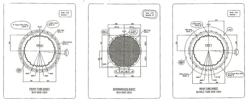
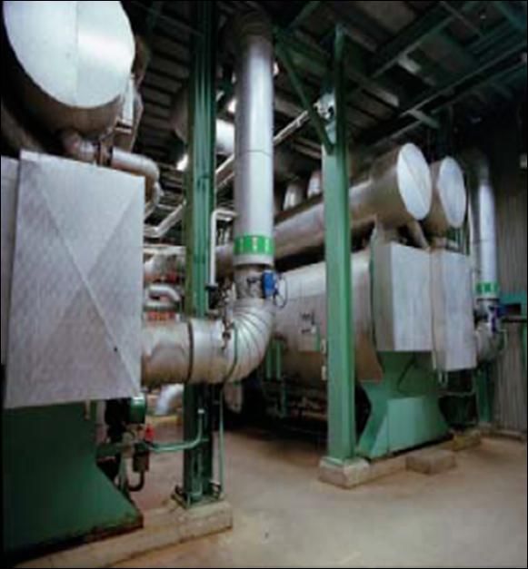
Thermodynamic modeling of absorption heat pumps
Master’s Thesis within the Sustainable Energy Systems programme
HELEN JARLROS

© HELEN JARLROS

Department of Energy and Environment
Division of Heat and Power Technology
Chalmers University of Technology
SE-412 96 Göteborg
Sweden
Telephone: + 46 (0)31-772 1000

Cover:
[One of the Sanyo absorption heat pumps at Renova waste incineration plant [5] ]

Chalmers Reproservice
Göteborg, Sweden 2010
Thermodynamic modeling of absorption heat pumps
Master’s Thesis within the Sustainable Energy Systems programme
HELEN JARLROS
Department of Energy and Environment
Division of Heat and Power Technology
Chalmers University of Technology

Abstract
In order to recover as much as possible of the energy released in the waste incineration
process at Renova, six lithium bromide absorption heat pumps are utilized to raise the
temperature of a recovered low temperature stream.
The recovered heat utilized in the absorption heat pumps comes from the flue gas cleaning
process, and is after the temperature has been raised in the heat pumps, delivered to the
district heating network.
Four of the six heat pumps is of an older brand called Sanyo and has nominal effect of 4MW
each. The two more modern heat pumps have a nominal effect of 6MW and are of brand
called Entropie.
As a part of an energy optimization project initiated at Renova, together with a consultant
company called “Energy project E&S”, the entire plant, including the absorption heat pumps,
have been represented in an Excel based model (here referred to as Model-Renova). This
model started with simple equations describing a small part of the energy recovery process
and the choice to use Excel as a base for the modeling, was explained by the simplicity of
Excel and the fact that Excel is a common and well known program,
The aim of this model is to find the optimal process solutions that would result in a more
optimal use of the energy released in the combustion.
The parts of the Model-Renova that represents the absorption heat pumps are based on
empirical correlations formulated from collected process data and represent the six heat
pumps as two units. The Model-Renova has an unknown range of validity, accuracy and a
limited possibility to model the individual heat pumps.
The accuracy of this heat pump model was evaluated by comparing the result of this model
with real process data. The old model has a fairly god accuracy in predicting the district
heating temperature, but give slightly over or under predicted estimations of the heat
recovered by the heat pumps and the coefficient of performance. However a possibility to
improve the model by changes in the governing equations could improve the accuracy.
This master’s thesis work focus on creating an improved model (New-model) of these heat
pumps with a better defined range of validity and the possibility to individualize the model to
each separate heat pump.
Some theoretical background concerning the heat transfer and the absorption heat pumps is
briefly presented in this report as a base for new models of the absorption heat pump.
Energy and mass balances along with common calculation methods used in calculation with
heat exchangers (the NTU method and the logarithmic mean temperature method) were used
in the representation of the absorption heat pumps as an excel base models (New model ).

                                               I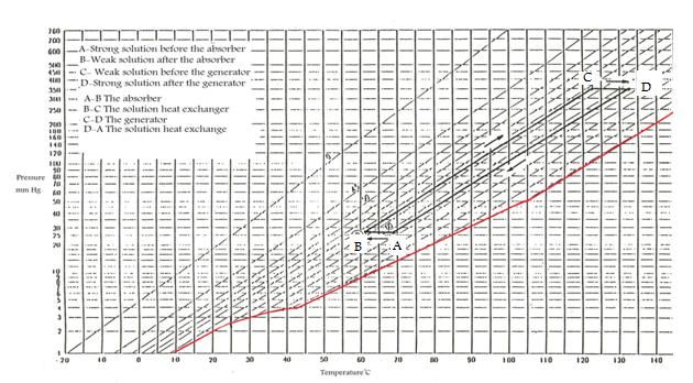
The two brands of heat pumps (Entropie and Sanyo) were modeled in two separate theoretical
models based on their design. These models should then be adapted to the six real heat pumps
by altering a factor on the heat transfer coefficient.
Due to some problems and difficulty in the modeling and the use of Excel as a modeling tool
descried in the report, only one of the two types of heat pumps was completely modeled.
It could also be concluded that the Model-Renova could, after some smaller alterations, be a
fairly god representation of the real heat pumps from a process perspective.
Key words: Absorption heat pump, Thermodynamic model

                                             II
Table of content
ABSTRACT                                                                       I

TABLE OF CONTENT                                                             III

NOMENCLATURE                                                                 VII

1     INTRODUCTION                                                            1
    1.1    Background                                                         1
    1.2    Objective                                                          2
    1.3    Scope                                                              2
    1.4    Method                                                             2

2     DESCRIPTION OF THE PROCESS                                              3
    2.1    Renova AB                                                          3
    2.2    The incineration plant                                             3
    2.3     The absorption heat pumps                                         4
       2.3.1    Working medium                                                6
    2.4     The heat pumps at Renovo waste incineration plant                 7
       2.4.1    Description of the four Sanyo machines                        7
       2.4.2    Description of the two Entropie machines                      9
    2.5    The overhead control system                                       12

3     THEORETICAL FRAMEWORK                                                  13
    3.1    Models in the literature                                          13
    3.2    Coefficient of performance                                        14
    3.3    Mass and energy analysis                                          14
    3.4    Absorption and desorption                                         15
    3.5     Heat transfer within the heat exchangers                         15
       3.5.1    The logarithmic mean temperature difference method (LMTD)    16
       3.5.2    The number of transfer units - NTU method                    17
    3.6    Boling point elevation                                            17
    3.7    Crystallization                                                   18
    3.8     Thermodynamic properties of lithium bromide and water solution   19
       3.8.1    Enthalpy                                                     19
       3.8.2    Saturation pressure                                          20
       3.8.3    Specific heat and density                                    21
    3.9     The Model-Renova and its limitations                             21
       3.9.1    Accuracy                                                     22

                                              III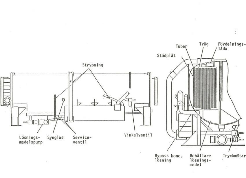
3.9.2     Advantages and disadvantages with the Model-Renova of the absorption heat
      pumps     26

4     CREATION OF NEW THE MODEL                                                27
    4.1    Mass balance and species balance                                    27
    4.2    Energy balance                                                      28
    4.3    Calculation procedure                                               28
    4.4     Properties                                                         32
       4.4.1    Enthalpy                                                       32
       4.4.2    Pressure                                                       33
       4.4.3    Specific heat and density                                      33
    4.5    Heat transfer coefficients                                          33
    4.6    The heat transfer efficiency parameter (ε)                          36
    4.7    Excel iteration                                                     37
    4.8    Assumptions                                                         37
    4.9     Accuracy of the iteration                                          38
       4.9.1    Iteration boundaries                                           38
       4.9.2    IF ERROR (OM FEL)                                              38

5     ADAPTION OF THE MODEL TO THE INDIVIDUAL HEAT PUMPS                       39

6     RESULTS                                                                  41
    6.1    Model: Sanyo                                                        41
    6.2    Model Entropie                                                      45
    6.3    Modeling issues and discussion                                      45
    6.4    Excel                                                               46

7     CONCLUSIONS                                                              47

8     FURTHER WORK                                                             49

REFERENCES                                                                     51

APPENDIX I: SYSTEM BOUNDARIES, HEAT PUMP                                       55

APPENDIX II: ABSORPTION HEAT PUMP, TECHNICAL DATA                              57

APPENDIX III: DRAWING OF THE ENTROPIE HEAT PUMP                                67

APPENDIX IV: ABSORPTION HEAT PUMP, MODELL-RENOVA                               69

                                               IV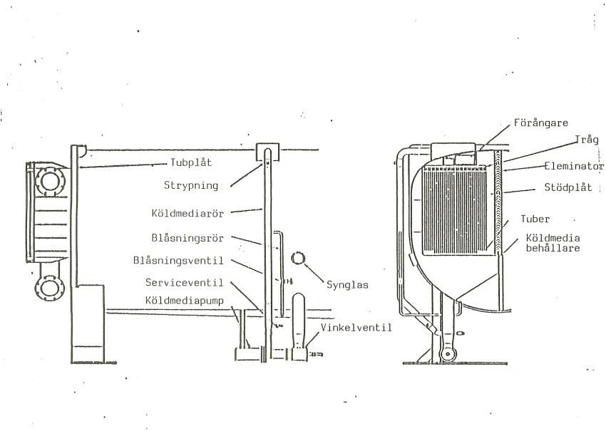
APPENDIX V: MODEL-RENOVA MODEL OF THE ENTIRE PLANT   71

APPENDIX VI: THE NEW MODEL                           73

APPENDIX VII: CALCULATION                            75

APPENDIX VIII: EQUATION SYSTEM                       83

APPENDIX IX: PROPERTIES CALCULATIONS                 87

                                 V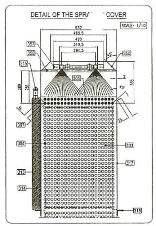
VI
Nomenclature

                                              [K]
LMTD= Logarithmic mean temperature difference
NTU = number of heat transfer units

Model-Renova = Existing model of the heat recovery process at Renova
New- model= Model created during this master thesis
DH-District heating
Strong solution – High mass concentration of lithium bromide
Weak solution – Low mass concentration of lithium bromide

Superscript

Subscript
 h=hot
c=cold

i=inside
o=outside

1, 2, …. .20 = stream number

                                        VII
VIII
1 Introduction
The continued growth of the world’s population and the increased standard of living will
bring out an increased demand for varies types of energy. The increase in the world’s energy
consumption is estimated by the American energy information administration, to be 44%
from 2006 to 2030 ([1] EIA Energy outlook report, 2009).
All energy production will result in some harmful influence on the environment including
global warming, emission of pollutions, land use and resource depletion.
As a way to manage the increasing amount of waste produced in the world and to contribute
to meeting the increasing energy demand, the waste is incinerated and the released energy is
recovered to produce electricity and district heating.
The energy produced in the waste incineration process can replace energy production by use
of combustion of fossil fuels. The amount of district heating produced in waste incineration
plants in Sweden each year could provide heat for 700000 villas and at the same time produce
enough electricity to supply 200000 villas. ([2] Avfall Sverige, Avfallsförbränning)
Using industrial heat pumps to make use of waste heat at low temperature can optimize the
heat recovered from the incinerated waste.

1.1      Background
As always in industrial processes there is a need to optimize the operation in order to get a
high overall efficiency of the plant. There is a project at Renova with the aim to find methods
to optimize the production. This project is conducted together with a consultant company
called “Energi projekt E&S (EPRO)”. A thermodynamic model of the whole process and all
important components has been made for this purpose (Model-Renova).
The Existing-model is built up in the software Excel and represents all parts of the energy
recovery process. The equations representing the different parts of the process have been
gradually improved and developed as the need for simulation of the different parts emerged.
These have sometimes been found from simple thermodynamic equations and correlations
between different parameters given as process data. All six heat pumps are modeled in the
same way from the same identical correlation.
 The accuracy and the range of validity in the Model-Renova of the heat pumps are somewhat
uncertain and a need for improvement was therefore identified.
The fact that the model does not consider the characteristics of each individual heat pump will
be a deficit in modeling operation changes or when the characteristics of the heat pumps
change as a result of rebuilding or aging. A need to get a more detailed model that can be
adapted to each individual absorption heat pump and their dependence on each other and the
surrounding process was recognized.
The equations and relations that constitute the Model-Renova are partly made up from
adaption of the model to measure data and might not give sufficient transparency and
understanding of the process.

                                              1
1.2 Objective
The aim is to create a model with an improved defined range of validity that can be converted
into the Excel format of the Model-Renova.
The model should be a good thermodynamic representation of the individual heat pumps and
be representative for the real heat pumps at different operation conditions. As the model will
be a detailed representation of the reality there will also be an option to alter the model as the
operation of the heat pump with aging and increased fouling on the equipment. This will also
give an understanding which parameters that are important for the performance of the
equipment.
The models should correspond to real measured operational data found from the real process
in operation.
1.3 Scope
Since the main purpose of the models will be to simulate a stationary system and not to
simulate failures or rapid changes, there will be no need to include transients into the model.
The limits for the model of the absorption heat pump cycles will be at the heat pumps input
and output of low pressure steam, condensate from the flue gas cleaning and the district
heating water respectively. (See Appendix I, figure 26)
An absorption heat pump is a complex machine containing several different components and
simultaneous mass and heat transfer. The amount of details in the model equations, should
therefore always subjected too careful considerations.
Some assumptions have been made concerning the state of steam or condensate at certain
points in the machine.
The properties of the working medium are assumed to be uninfluenced by properties of the
additives included in the working medium.
1.4 Method
Existing literature was evaluated to find thermodynamic models that are used for simulating
heat pumps. The examined correlations and models will, together with knowledge obtained in
courses within the master program, be used when constructing the model for this application.
An evaluation of the accuracy of the model is made by statistics analysis of process data. The
resulting model will then be adjusted to represent the individual heat pumps. This will
characterize how the heat pumps differ in their operation.
22 Description of the Process
2.1 Renova AB
Renova AB is a waste management and recycling company owned by 11 municipalities in the
western part of Sweden. The company takes care of various types of waste coming from both
households and industry.
After the waste has been discarded and sorted into hazardous waste, recyclable, compostable
and combustible waste it is transported by garbage trucks to Renova´s different waste
management facilities.
2.2 The incineration plant
The part of the waste that is combustible is incinerated in Renova's incineration plant.
The incineration plant is located in Sävenäs close to the small river Säveån outside
Gothenburg. The plant produced 228 GWh of electricity and 1197GWh heat in 2009 which
corresponds to about 5% and 26% of Gothenburg’s electricity and heat need respectively ([3]
Renova AB, Miljörapport, 2009).
There are four furnaces installed to combust the allowed amount of waste, around 550000
tons per year. ([4] Renova AB, Homepage )
The waste is combusted from a sloping grate in the bottom of the furnace. The grate is
penetrated by a part the combustion air coming from beneath the grate.
As a way to reduce the formation of nitrogen oxides, the combustion is first preformed in a
fuel rich conditions and the rest of the air is introduced higher up in the combustion chamber.
Nitrogen oxides are also further reduced by injection of ammonia, a so called selective non-
catalytic reduction (SNCR) ([5] Renova AB, Waste to energy plant in Göteborg).
The walls in the combustion chamber are covered with tubes containing water. The water
within the tube wall will be evaporated into saturated steam.
The steam is superheated to 400°C and 40 Bar in the superheater, located after the combustion
chamber. The temperature of the flue gases leaving the superheater will be rather high and is
therefore used to preheat the water in a feed water economizer.
As the flue gases leaves the feed water economizer they enter an electrostatic precipitator that
is used to clean the flue gases from large particles and soot.
The flue gas will then be cooled down from about 230 °C to 140 °C in a flue gas economizer
by heating the district heating.
The next step is the wet flue gas cleaning consisting of a wash reactor and a condensing
reactor. The heat released in these processes is delivered to the district heating via six
absorption heat pumps. The flue gas will then be reheated by use of steam and as a last step
the flue gases are cleaned in a fabric filter before it leaves the process in the chimney. (Figure 1)
The superheated steam leaving the superheater is expanded in a turbine that is connected to a
generator producing electricity. The electricity produced is delivered to the electricity grid via
a transformer.
Not all of the steam will pass all the way through the turbine; some steam is extracted at
intermediated levels 3, 5 and 7 bars. The wet steam that passed all the way through the turbine
will be condensed in a heat exchanger that will deliver heat to the district heating network.
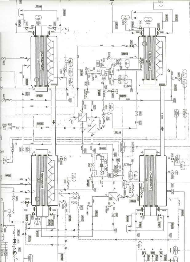
3Figure 1. The entire energy recovery process at Renova waste incineration plant
2.3 The absorption heat pumps
The second law of thermodynamic states that:
Energy has both a quantity and a quality and that all spontaneous processes occur in the
direction of decreasing energy quality.
This means that heat can only be raised from a low temperature to higher temperature by
introducing some form of higher quality energy.
Not so many practical end applications where energy at a low temperature can be utilized,
which means that there is a need for a technical solution that can, without violating the second
law of thermodynamics, bring low temperature energy up to a higher temperature. A heat
pump or a heat transformer is used to do just that.
A common application for a heat pump is to recover low temperature waste heat that cannot,
due to the low temperature, be used for other purposes within the process and bring it to a
more useful temperature.
The cycle can also be inverted in order to accomplish cooling (e.g. refrigerator) when the heat
is removed from a cooled space and delivered to the higher temperature surrounding.
There are several different types of heat pumps and heat transformer technologies. The most
common type of heat pump is the compression heat pump that accomplishes an increased
temperature due to the fact that the working medium has a different boiling and condensing
4temperature at different pressures. A compressor powered by some form of work, for instance
electricity, is then used to create the pressure difference within the heat pump.
Another approach is to use steam to raise the temperature up to a desired level, which is the
case in an absorption heat pump. An absorption heat pump will instead utilize the increased
boiling point of the solution compared to the boiling point of the pure substance. Steam is
then used instead to drive the heat pump cycle as describe bellow.
Absorption heat driven heat pumps can be divided into two different types. Type I is a cycle
where heat is introduced at both a high and a low temperature and the heat deliver from the
heat pump has an intermediate temperature.
In the type II heat pump, heat will be introduced at an intermediate level and output heat will
have both higher and lower temperatures ([6] Herold, Keith 1996)
The absorption heat pumps considered here are of the first type.
Absorption heat pump cycle can be divided in one two or several effects meaning that the
generator and condenser have been divided into two or more stages with an additional
solution heat exchanger, in order to improve the heat pumps efficiency ([6] Herold, Keith
1996).
The basic components included in the absorption heat pump are made up by heat exchanges
with some alterations (2.4.1 and 2.4.2) and are described below.
Weak solution referrers to as dilute solution with a relatively low concentration of lithium
bromide compared to the strong solution that has a high concentration of lithium bromide.
Figure 2: A single effect absorption heat pump
5Evaporator
The saturated water coming from the condenser into the evaporator will evaporate into steam
due to the low pressure within the evaporator by use of a low temperature heat source. The
temperature of evaporation will then be around 30-40 °C and the heat required to evaporate
can, due to the low pressure (around 0, 08-0, 04 bar), be made up by low temperature waste
heat.
Absorber
The steam entering the absorber will be absorbed by a salt solution in an exothermic reaction.
The week solution will have a higher boiling temperature than the boiling point of water and
will therefore condensate. The heat realized in the condensation will be delivered to the
district heating network.
Generator
The generator requires low pressure driving steam to evaporate the water out of the weak salt
solution in an endothermic process. The strong salt solution is returned to the absorber while
the evaporated water solved from the solution continues to the condenser.
Heat exchanger (HX)
A heat exchanger placed between the generator and the absorber will utilize the heat in the
strong solution returning to the absorber to pre-heat the week solution before it enters the
generator.
Condenser
The steam coming from the generator is condensed and heat is delivered to the district heating
network. The condensed water is then returned to the evaporator and the cycle is completed.
2.3.1 Working medium
The working medium includes both the solution and the pure component and consists of one
volatile and one non-volatile component. The working medium is most often made up by
water as a volatile component together with the non-volatile component consisting of lithium
bromide or ammonia as a volatile component and the non-volatile water.
All heat pumps at Renova operate with a working medium consisting mainly of water and
lithium bromide. Lithium bromide is chemical compound of Lithium and Bromide and has a
melting point of 547°C. Lithium bromide is soluble in water, alcohol and glycol and looks
like a white powder ([7] Chemland,21) .
Using Lithium bromide/water solution as a working medium compared to the use of water /
ammonia solution has advantages and disadvantages. The efficiency of a single stage heat
pump is increased when using lithium bromide/water compared to using water/ammonia.
The specific heat of water/ammonia solution is also about twice as high as for the lithium
bromide/water solution causing any higher losses (irreversibility) as a result of inefficiency in
the heat exchangers ([6] Herold, Keith 1996). The latent heat of water/ammonia solution is also
6about half the heat released as the lithium bromide solution changes phase resulting in a higher
flow of the refrigerant to achieve the same heat or cooling effect ([6] Herold, Keith 1996) .
A mayor disadvantage when using a salt solution like Lithium bromide salt solution is the risk
of crystallization (se section below) that will restrict the operation of the absorption heat
pump. Ammonia and water solutions is most often used when temperatures goes under zero in
cooling heat pumps.
In order to prevent both corrosion and crystallization and also to increase the heat transfer
giving an enhancement of the performance of the absorption heat pump, some additives have
been included in the working fluid.
2.4 The heat pumps at Renovo waste incineration plant
The six heat pumps installed at Renova are of two different brands with a design that deviate
somewhat from the general description above. Four of the heat pumps are of an older brand,
manufactured by a company called SANYO. They have a nominal cooling effect of 4MW i.e.
they can cool 4MW from the low temperature heat source.
The two more recently installed heat pumps are of a brand called Weir/ Entropie and have a
more modern design and construction. They have a nominal cooling effect of about 6MW each.
2.4.1 Description of the four Sanyo machines
The four Sanyo heat pumps had identical design at the time of installation year 1988.
The heat pump machines are based on the absorption heat pump cycle but include one
additional condensate after cooler heat exchanger and utilize a solution consisting of Lithium
bromide and water as a working medium.
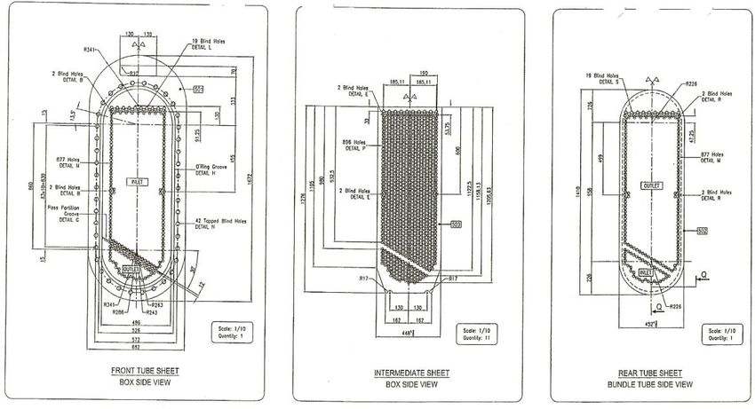
7Figure 3: Sanyo absorption heat pump
Construction
The bottom of the heat pump consists of a large tube shaped vessel that contains both the
evaporator and the absorber. The working medium is separated between the evaporator and
the absorber by use of a fluid separator. The liquid that have not been vaporized as it passed
the tube bundle in the evaporator is collected in the bottom below the tubes and circulated up
to the top again. (See APPENDIX Figure 25-26)
The low temperature heat source from the flue gas condensation and the district heating water
is lead through a tube bundle in the evaporator and absorber respectively. Located above the
tube bundles are distribution tubes that have the objective to distribute the working fluids
evenly over the tube bundle.
The evaporator can be considered as a four pass tube heat exchanger and the absorber as a two
pass heat exchanger.
The driving steam is condenses as it is circulated within the tubes in generator order to
separate the water from the Li/Br solution. The generator can be considered as a one pass
evaporator where pool boiling occurs. (See APPENDIX Figure 27)
Evaporated water from the generator is entered in the condenser above the one pass tube
bundle and the condensed water from a film on the tubes surface. The district heating water
circulates within the tubes and will in that way recover the heat from the condensing steam.
(See APPENDIX Figure 28)
Some heat in the strong solution leaving the generator is recovered as it is circulated in the
tubes of a tube and shell heat exchanger (solution heat exchanger). The heat is transferred to
the weak solution as it passes through outside the tubes on the shell side of the heat
8exchanger. Both the strong and the weak solution pass through the heat exchanger three
times. (See APPENDIX Figure 29)
The condensed steam leaving the generator has a substantially high temperature and needs to
be sub cooled in order to be handled in the collection container.
This is done through heat exchanging with the weak solution before they are entered to the
generator .This is done in parallel with the weak-strong solution heat exchanger in the
condensate after cooler. The condensate after cooler heat exchanger is a tube and shell heat
exchanger where the condensed steam circulates inside the two pass tubes and the weak
solution outside the tubes ([8] Sanyo manufacturing files).
Control system
The Sanyo heat pumps have been equipped with two different control systems connected via a
min selector, in order to control the pressure on the driving steam.
The first system controls the level of working fluid inside the evaporator.
More condensate from the condenser enters the evaporator than can be vaporized in the
evaporator lead to an increased liquid level in the bottom of the evaporator.
When steam pressure of the driving steam entering the generator decreases, less water will be
evaporated out of the solution and will leave the generator as steam. The decreased flow of
evaporated water from the generator will result in a decreased flow of condensate from the
condenser into the evaporator. This decreased flow will in turn lead to a lowered water level
at the bottom of the evaporator.
An increased level of water in the bottom of the evaporator will mean that more water is on
the water side (condenser and evaporator) and less water will be on the solution side (absorber
and generator). The decreased amount of water on the solution side will mean that the
medium concentration of Lithium bromide between the strong and the weak solution
increases. A conclusion will therefore be that the liquid level in the evaporator is in
proportional to the medium concentration of lithium bromide.
The second system regulates the steam demand depending on the desired outgoing
temperature of the cooling water (MKS water).
The control system with the lowest control value will be the one that is selected. The system
controlling the fluid level have been designed in order to minimize the steam consumption
and will most often be the one giving the lowest signal and therefore be the prioritized signal.
This is an important feature since the plant will always will be regulated in order to maximize
the steam through the turbine and therefore maximize the production of electricity ([8] Sanyo
manufacturing files).
2.4.2 Description of the two Entropie machines
The two more modern heat pumps have a more advanced design and control system than the
four older heat pumps, but are based on the same absorption heat pump cycle. However the
design of the Entropie heat pumps includes, as in the Sanyo heat pumps, a condensate after
cooler that is in this case mounted on the district heating water. The design also includes an
additional heat exchanger in parallel to the absorber.
9These heat pumps were installed 2003 and are identical in their initial design. These heat
pumps also utile a solution manly consisting of lithium bromide and water as a working fluid.
Figure 4: Entopie heat pump
Condenser
Absorber
Evaporator
Generator
Figure 5: The front side of the Entropie absorption heat pump [9]
10The tube bundle in the evaporator is divided in three parts as a three pass heat exchanger. The
evaporated steam passes leaves the evaporator for the absorber and the water that still is in a
liquid phase is collected in the bottom of the evaporator where it is mixed with the water
coming from the condenser.
A pump is used to pump the collected liquid up on top of the evaporator where the water is
sprayed down on the tube bundle from pressurized nozzles located above the tube bundle.
The steam from the evaporator enters the absorber from above the tube bundle and the steam
is absorbed by the strong Lithium bromide solution. The district heating water circulates
inside the two pass tube bundle containing aligned tubes.
A circulation pump is used to bring the solution from the low pressure in the absorber to the
high pressure in the solution heat exchanger, generator and condenser.
The solution heat exchanger is designed as a cylindrical plate and shell heat exchanger that
will transfer heat from the warm strong solution coming from the generator to the weak
solution coming from the absorber. As the strong solution coming from the absorber enters
the generator it is sprayed down over a one pass tube bundle circulated with condensing
steam. In this way the Lithium bromide and the water is being resolved from each other.
The condenser can be seen as an ordinary one pass tube and shell condenser where the tube
bundle is constructed in a cylindrical and staggered manor. The district heating water is
circulated inside the tubes as the steam coming from the generator is condensed outside the
tubes. The steam is entered above the tubes and the condensate is collected underneath the
entire tube bundle.
Some of the reaming heat in the condensate is recovered and transferred to the district heating
network after the condenser. The condensate after cooler is also constructed as a cylindrical
plate and shell heat exchanger.
A plate and shell heat exchanger is mounted parallel to the absorber on the district heating
side and is used to recover heat from the condensate coming from the condenser and make
sure that it is in a saturated state.
Control system
The Entropie heat pumps have been equipped with an advanced control and regulations
system in order to optimize the operation and to avoid crystallization.
The system includes several temperature and pressure measurement and rupture disk to
protect against high pressure and temperature in the condenser as well as in the district
heating water.
A main concern when designing a control system for an absorption heat pump is the risk of
crystallization (see explanation below). The protection against crystallization includes
measures to sustain a god circulation and to keep a sufficient low level of Lithium bromide
concentration ([9] Entropie manufacturing files).
The temperature difference between the strong solution after the generator and the
temperature of the weak solution before it enters the generator corresponds to the boiling
point elevation of the weak solution. The boiling temperature elevation is, as described in a
section below, connected to the concentration of the solution and need therefore be monitored
in order to control the risk of crystallization.
11The liquid level in the bottom of the evaporator and generator is controlled by the circulation
pumps circulating the liquid faster or slower in order to decrease or increase the heat transfer
and an therefore decrease or increase the level.
The liquid level in the condenser is controlled by the opening of two valves in the bottom of
the condenser that regulates the outflow of condensate.
2.5 The overhead control system
The district heating water is a part of the wide spread integrated district heating network that
delivers heat to many customer at different geographical location and from several heat
producing units. This system is owned and controlled by an energy company called
“Göteborg Energi” that manages this complex network. The water flow and ingoing and
desired outgoing temperature is therefore predetermined and controlled by “Göteborg Energi”
as the water enters the plant at Renova.
The district heating pipes to the heat pump units are designed in a parallel design to the big
district heating pipe so that they take water from the district heating network and return it at a
higher temperature.
The four Sanyo heat pumps and the two Entropie heat pumps have separate pipes connected
to the district heating network.
The district heating flow to the two Entropie Heat pumps are regulated by frequency regulated
pumps that is controlled from the control room.
In case the heat pumps demand more water from the district heating network than the
incoming district heating water flow into the plant the water will move backward in the
district heating lines and be lead through the heat pumps once more. This will result in a
higher temperature of the district water coming into the heat pumps and therefore a lower
efficiency of the heat pumps.
Figure 6: The six absorption heat pumps connected to the district heating network
123 Theoretical framework
An absorption heat pump is a very thermodynamically complex machine that can be described
by chemical, mechanical and heat interactions.
As any system, the heat pump must obey by both the first and second law of thermodynamics,
meaning that no energy or mass can be created or destroyed within the system and that no
heat can directly be transfer to a higher temperature without addition of some external work.
Since the system mainly consists of heat exchangers in different executions, a parameter that
strongly influencing the performance of the heat pump is the heat transfer area and heat
transfer coefficient between the two fluids of each heat exchanger.
3.1 Models in the literature
Absorption heat pumps have been modeled by several different authors for the purpose of
simulating different aspects of the heat pump.
According to Qin many of the developed models and investigations have been focused on a
finite-time thermodynamics .The finite time -thermodynamics (or finite-size thermodynamic
or endoreversibility or entropy generation) analysis is most often used in order simulate the
optimization of operation of the absorption heat pump including the internal irreversibility,
heat leakage and losses with heat resistance. ([10] Qin et.al 2007).A finite time analysis
results in many advanced equations and require a powerful calculation tool and will therefore
not be used in the model created here.
Using the second law of thermodynamics to model the entropy generation or to perform an
exergy analysis on the heat pump in order to evaluate the performance of the absorption heat
pump, have been done by several researchers including Sencan and Wolf ([11] Sencan et.al
2004), ([11] Wolf .et.al 1988)
Many of these analysis focus on locating the sources of losses and finding design possibilities
to decreases these losses by an optimal design of the absorption heat pump system and the
area distribution, and might therefore be more used in a design aspect of the heat pump where
the heat pump configuration and area distribution in the included heat exchangers are design
variables.
A model that is frequently mentioned and referred to in the literature is the “ABSIM” model
(ABsorption SIMulation) developed by Gershon Grossman. This model is used to investigate
different cycle configurations of absorption systems in steady state conditions ([13]
Grossman et.al 2001). The code in this model is constructed in a modular way as subroutines
for each component solving the governing equations. The ABSIM model is used to evaluate
different cycle configurations and working fluids and simulate absorption systems at off
design operation.
A less complex approach is to model the absorption heat pump by considering the mass,
species and heat balances. This approach was taken in the modeling of absorption heat pump
cycles by Keith Herold who made in a special version of the Engineering Equation solver
(EES) software. ([6] Herold, Keith 1996)
The approach taken in this model is suitable for simulating a steady state operation found in
the modeling of an existing heat pumps operation and will therefore serve as a base for the
modeling in this master thesis work.
133.2 Coefficient of performance
When describing the efficiency of a process it is common to refer the required energy input
divided by the useful energy generated by the process as a way to describe how efficient the
process convert the input to desired output.
When referring to a heat pump cycle it is more common to use the coefficient of performance
that will compare the work or driving steam required to produce the useful output.
The coefficient of performance will often exceed one and can therefore not be considered to
be a true efficiency. Efficiency that is higher than one would mean that more useful energy
output would be created in the machine than is required as energy input which would violate
the first law of thermodynamics.
What is considered as the required energy output differs if the heat pump is used as a cooling
machine or as a heating machine i.e. when a cooling machine is considered the required
output is the amount of heat that you cooled off and in a heating machine the amount of the
heat delivered.
( [6] Herold, Keith 1996)
As the heat pumps considered here is used to heat the district heating system, only the last
expression of the COP will be considered in this report.
3.3 Mass and energy analysis
A common approach when conducting energy and mass balance of an absorption heat pump
system is to consider each component as a separate control volume where inlet and outlet
steams flows cross the system boundary of each control volume .
Mass and energy balance is based on the first law of thermodynamics meaning that the mass
and energy flow into a system is equal to the change of mass and energy inside the system and
the mass and energy flow out of the system.
The same goes for all individual components in the flow when no reaction occurs between the
components.
The mass and energy balance equations for each individual component was stated, and all
components was connected together to form the entire heat pump unit by linking inputs and
outputs between the different control volumes. (See figure 15)
143.4 Absorption and desorption
The water vapor entering the absorber is absorbed into the strong solution.
The result of mixing two different species like water and Lithium bromide is not that the
enthalpy of the solution will be the mass-weighted average of enthalpies.
When water is absorbed into the strong Lithium bromide solution, it will result in an enthalpy
of the diluted solution that is less than the weighted average enthalpy meaning that the
absorption process is exothermic i.e. heat is released to the district heating water (heat of
solution). ([6] Herold, Keith 1996).
In adiabatic system this would result in an increased temperature but as the absorber in the
heat pump is constructed as heat exchanger .i.e. not an adiabatic system, the released heat will
be delivered to the district heating water.
3.5 Heat transfer within the heat exchangers
Heat is transferred from a stream with higher temperature to a stream with lower temperature
in heat exchangers.
The process of heat transfer occurs in three different ways, conduction through the tube wall,
convection outside the tube wall and radiation. As the temperature difference the working
fluid and the tube wall in heat exchanger tend to be small the heat transferred by radiation can
be neglected.
The heat transferred between the two streams can be described as:
U is the overall heat transfer coefficient which describes the above mentioned heat transfer
processes by including coefficient for the conduction and convection as well as the fouling
resistance both inside and outside the tube.
The heat transfer is not constant throughout the whole heat exchanger and U will therefore be
seen as an average value over the entire heat exchanger. The fouling resistance is the heat
transfer resistance caused by dirt that is stuck on the tube wall.
The amount of heat that can be transferred per area unit is determined by the shape of the heat
exchanger as well as the temperature and velocity of the fluids, the boundary layer
surrounding the heat exchanger area and the process occurring in the heat exchanger.
153.5.1 The logarithmic mean temperature difference method (LMTD)
The temperature changes within the heat exchanger will result in a varying driving force
throughout the length of heat exchanger as a result of varying temperature difference between
the hot and the cold fluid. As the hot fluid heats the cold fluid and the temperature difference
between them decrease resulting in logarithmic temperature profile through the length of the
heat exchanger. (Figure 14)
Figure 7: Temperature variation, Top row left parallel flow, Top row right condensation,
bottom row left evaporation, bottom row counter flow
As the driving force and the temperature difference between the hot and the cold stream
changes along the heat exchangers length it is not representative measurement of the driving
force to take the difference between the two inlet streams.
In order to formulate a better estimation of the mean driving force throughout the heat
exchanger, an integration of the differential equation describing the change in the temperature
difference between the hot and the cold streams within a counter current is made.
16To represent other heat exchange designs a correction factor Ft is used to calculate the
corresponding logarithmic mean temperature difference.
The logarithmic mean temperature difference is used instead of the temperature difference in
the above expression of the heat transferred. (Equation 3.5.1)
3.5.2 The number of transfer units - NTU method
In calculations where only the inlets temperatures are known, the logarithmic mean
temperature difference method requires a sometimes very big iteration process.
A simplified method to evaluate the heat exchangers performance is called the Number of
Transfer Unit method or the NTU method.
This method is based on the maximal amount of heat that theoretically could be transferred
between the two streams (Qmax) and a dimensionless parameter called the heat transfer
effectiveness ( ) ([14] Incropera 2005)
The heat transfer effectiveness is the relation between the actual heat transferred and the
theoretical maximum heat transferred.
The heat transfer effectiveness depends on the type of heat exchanger and the flow pattern and
is calculated from the heat capacity rate (C=Cp* ) of the two streams and also the number
of heat transfer units ( ).
The maximal theoretical heat that can be transferred between the two streams will be
calculated based on smallest of the heat capacity rates (Cmin) and the difference between the
two inlet temperatures. ([14] Incropera 2005)
As the temperature of the stream changes the specific heat will be calculated at a mean value
of the inlet and outlet temperatures. This simplification will only be valid when the specific
heat is fairly constant i.e. no big changes in temperature or concentration.
3.6 Boling point elevation
As the concentration of Lithium bromide decreases by the absorption of water in the absorber,
the saturation temperature will increase.
This increased saturation temperature will in the low pressure result in the condensation of the
water in the solution.
The opposite occur in the generator where the water is boiled of resulting in a decreased
saturation temperature. The difference between these two temperatures is the boiling point
elevation. The boiling point elevation is measured as the difference between the temperature
of the strong solution out from the generator and the weak solution coming from the absorber.
17This change in the boiling temperature with different concentrations is the principle that
enables the absorption heat pump to move heat from a low temperature heat source up to a
useful temperature.
Since the boiling point is a function of the lithium bromide concentrations, the boiling point
elevation can be used as a measure of the concentration in the solution in order to prevent
crystallization (see section 3.8).
3.7 Crystallization
Crystallization is, when the concentration of the salt exceeds the solubility limit, causing
precipitation of the salt component.
The solubility is a strong function of the mass fraction and temperature and a weak function
of the pressure.
Once the salt has started to precipitate it forms crystals that enhance the possibility for further
creation of crystals. The formation of crystals will accelerate and continue even though the
satiety has declined. The crystals can the clog the system and create blockages in the flow
([6] Herold, Keith 1996)
To reduce the risk of crystallization in a Lithium bromide heat pump the temperature needs to
be sufficiently high and the concentration be sufficiently low.
The highest risk for crystallization is when the strong solution has been cooled by the solution
heat exchanger. This is the point where the concentration is highest and the temperature is
lowest. (See point A in figure 15 below)
Pressure
mmHg
Temperature
TemperatureCC
Figure 8: Crystallization line, absorption desorption ([8] SANY
183.8 Thermodynamic properties of lithium bromide and water
solution
The thermodynamic properties of the lithium bromide solution are essential to get a god
thermodynamic representations of the processes in the absorption heat pump.
The temperature of the working fluid in the considered heat pumps varies from the high
temperatures in the strong solution to the low temperatures of the weak solution leaving the
absorber and the concentrations varies from the weak concentration to the strong
concentration. The thermodynamic properties must therefore be valid for a temperature range
of about 30 °C to 130 °C and for mass fraction 0, 3-0, 8 (kg/kg).
Many articles have been made over the properties of lithium bromide/water solutions. An
often used formulation of the properties of Lithium bromide is made by McNeely and has
validity between 15 °C up until 166°C. ([15] Klomfar J Patek 2006)
The properties for the lithium bromide/water solution is calculated from an empirical
correlations valid between 273K (unless the crystallization temperature is larger than 273K)
and 500K and from 0 to 75% lithium bromide concentration, which was found in an article by
J. Pa’tek, JKlomfar ([15] Klomfar J Patek 2006).
3.8.1 Enthalpy
The polynomial to find the enthalpy from the temperature and the concentration consist of 31
terms in a summation.
([14] Klomfar J.Patek 2006)
It can be seen in the figure below that the enthalpy of the solution will decrease as the
concentration increases and obviously also decrease with decreasing temperature.
The enthalpy at zero concentration is the same as for pure water which could be expected
(figure 16).
19227
T[C]
0
Figure 9: Enthalpy of the Lithium bromide/ Water solution
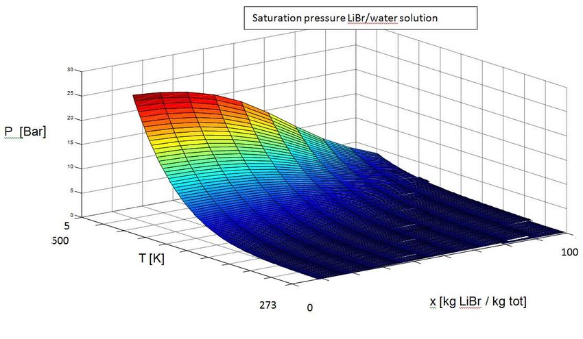
3.8.2 Saturation pressure
The saturation pressure of the solution is calculated from the polynomial bellow. In
comparison to the polynomial to calculate the enthalpy the saturation pressure only includes 8
terms.
([15] Klomfar J Patek 2006).
227
T[C]
0
Figure 10: Saturation pressure of the Lithium bromide/ water solution
20The saturation pressure will of course decrease with the temperature in the same way as for
pure water, but will also decrease with decrease with increasing lithium bromide
concentration.
This behavior is the reason for that the absorption heat pump can move heat from a low
temperature to higher temperature
3.8.3 Specific heat and density
The equations used to calculate both the specific heat (Cp) and the density (ρ) for the lithium
bromide and water solution are calculated from a similar polynomial as for the enthalpy
includes fewer terms
:
([15] Klomfar J Patek 2006).
([15] Klomfar J Patek 2006).
3.9 The Model-Renova and its limitations
The Model-Renova have been implemented in Excel and covers the whole steam cycle from
the generation of steam in the furnace, the turbine, and the steam headers to the point when
the water return to the furnace as well as the heating of the district heating water and the
thermodynamic aspects of the flue gas cleaning process. (Appendix V)
The model was built in a very simplified approach and has been gradually improved as the
need for simulation of certain parts of the process has emerged.
The Model-Renova of the absorption heat pump represents the four smaller Sanyo machines
as one unit and the two lager Entropies machines as one unit. (Appendix IV)
The model is based on process data collected for one of the Entropie heat pumps. This heat
pump is then modeled by an empirical correlation of how the heat recovered from the flue gas
cleaning system varies with the temperature in the outgoing district heating water,
temperature of the incoming water from the flue gas cleaning and the driving steam pressure.
The same procedure was used for a correlation of the coefficient of performance (COP) as a
function of the incoming district heating temperature.
This correlation is then altered with respect to the nominal cooling power to be valid for the
small Sanyo heat pump. The units representing the two Entropie heat pumps and the four
Sanyo heat pumps are therefore described by multiplying this correlation with a scaling factor
according to the nominal effects.
The COP value is then used to calculate the resulting heat delivered to the district heating and
also the steam consumption.
21The model is also equipped with two correction factors meant to describe the situations when
not all of the heat pumps are running. One factor describing the division of district heating
water between the two units and one factor that describes if the calculated COP value is
expected to be under or over estimated in this particular operation condition.
3.9.1 Accuracy
The accuracy of the Model-Renova has been evaluated by comparing the results of the model
with actual process data from the real heat pumps used as input. The available database
located on sight (OPTIMAX) has been used to collect process data from every hour from
2009-07-03 to 2009-12-10 (3842 time samples).
The model of the absorption heat pumps has been isolated from the process model and all
inputs from the surrounding model were identified. (Se Appendix IV)
The model of the absorption heat pumps was equipped with four factors
Factor S- Determine how many of the four Sanyo heat pumps currently in use (0, 5=2 heat
pump are stopped). This factor was entered as how many of the heat pumps that were on,
divided with 4.
Factor E- Determine how many of the two Entropies heat pumps currently in use (0, 5=1 heat
pump are stopped).This factor was entered as how many of the heat pumps that were on,
divided with 2.
Factor V- A factor that can correct for known overestimations of the COP in certain process
cases. As this factor is an estimation done manually as the model is operated I put this factor
to 1.
Factor F- Determine how much of the district heat flow that will be re circulated between the
heat pumps.
The difference between the measured process data and the predictions from the model was
divided with the measured value to get a relative error.
In order to see if there was any continuing trend in the errors i.e. that the model always
predicts a too high or too low value, the frequency of the relative errors was plotted.
Table 1: Mean value and variance of the relative error
Mean value of the Variance of the
relative errors (%) relative error
DH temperature -0,0207 0,000522
Q Sanyo -0,0157 0,0373
Q entropie -0,003 0,0610
COP Sanyo -0,0157 0,00538
COP Entropie -0,0225 0,00572
22QDH Sanyo
Outgoing district
heating temperature
% Relative error
COP Sanyo
Q DH Entropie
COP
Entropie
Figure 11: The frequency of the relative error
Based on figure 11 it can be noted that the relative errors are somewhat centered around a
value on the right or left side of the zero value. A mean value of the relative errors has been
calculated and is given in the table above (table 1). The variance of the relative errors has also
been calculated as a measure of the distribution of the relative errors around the mean value.
A high variance, meaning a high distribution of the errors, could mean that the result of the
model is quite inaccurate even though the mean value is close to zero.
23As the models errors are about 1-2 % of the measure process it can be concluded that the
model are a god representation of the absorption heat pumps during the considered time span.
The relative errors of the district heating temperature have a peak near the zero, meaning that
the model is a god prediction the outgoing district heating temperature in several of the
process cases. However the distribution of the relative errors is quite broad and the prediction
of the outgoing district heating temperature have been over estimated in many of the process
cases.
The peak of the relative error on the calculated heat transferred to the district heating system
shows, as can be seen in the figure 11 above, that the model over predicts and under predicts
the heat transfer in the Sanyo and the Entropie heat pumps respectively with about 12-22 % .
It should also be noted that the process data have been collected as a time discrete sample
where the process might not be in stable operation, and that the data was collected from
measure equipment with unknown accuracy. This can explain some of the more extreme
errors but since process data have be collected for an entire year the focus have to be on the
bulk of errors.
24Figure 12: Scatter plot, Process data / Modeling results
The results from the Model-Renova were plotted as a function of the measured process data
for the previous mentioned process parameters to form scatter plots (Figure 12).
All samples would end up at in alignment with the straight diagonal line (Y=X) if the model
always predicted all properties to be equal to the corresponding measured value.
The scatter plots of the result of the tested made on the old model, during this period show
that the Model-Renova of the absorption heat pumps predicts the temperature of the outgoing
district heating water and the district heating effect fairly accurate.
However the heat transferred to the district heating water in the two Entropie heat pumps will,
according to this plot, deviate from the measure value at higher heat transfers.
25The estimations of the COP efficiency is more spread out in reality then the model is
predicting for both the Sanyo and the Entropie heat pumps.
3.9.2 Advantages and disadvantages with the Model-Renova of the
absorption heat pumps
The Model-Renova is a simplified representation of the reality as it basically represents the
group of heat exchangers by one empirical correlation. The simplicity of this model makes it a
robust representation of the reality and will, as it is based on analysis of real process data,
incorporate all uncertainties in the process.
As the model basically only consist of a few main equations and some surroundings energy
and mass balance equations, it can be modeled using only a limited computer size and can
therefore easily be incorporated into the Model-Renova.
Advantages
Simplicity
God accuracy
Small computer capacity needed
Based on process data
Since the model is build up around process data, collected at discrete time points where the
operation was assumed to be representative, there is an uncertainty concerning the range of
validity. The model can therefore be expected to deviate from the reality in operations that
differs considerable from the operation at the time when the process data was collected.
As the model represents the six heat pumps like two units there is no possibility to analyze
how the individual heat pump operates and how changes and rebuilding in one or a few of the
heat pumps affects the total operation in of the plant.
The exciting model simulates the operation when one or more of the heat pumps have been
stopped by the previous mentioned factors (S and E). These factors only affect the heat
transferred to the district heating network and do not take into account the reduced flow of
district heating water to the heat pump units.
Disadvantages:
Unknown range of validity
Do not model each separate heat pump
Hard to model when one or more of the heat pumps have been turned of
264 Creation of new the model
The absorption heat pump will, in reality, experience inputs from the surrounding system
including temperature and mass flow of incoming district heating water and MKS water as
well as steam data and flow. As the heat pump cools the MKS water and heats the district
heating water, it will deliver “out data” to the surrounding system in form of temperatures of
the outgoing district heating water, the MKS water and the condensate coming from the
condensate after cooler.
The absorption heat pump can be seen as a network of heat exchangers assembled in such a
way to achieve an indirect transfer of heat from one temperature level to another. The model
is therefore created as separate heat exchangers with inputs as temperatures, pressures, mass
flow rates and concentrations calculated in surrounding process models.
4.1 Mass balance and species balance
The mass balance in all components, except for the absorber and the generator, is trivial as the
mass flow in to the component equals the flow out of the component at steady state
conditions.
The mass flow of water vapor in to the absorber from the evaporator together with the mass
flow of the strong solution coming from the generator will equal the mass flow of the weak
solution leaving the absorber.
In the same way the mass flow of the weak solution entering the generator will equal the
steam passing in to the condenser and the strong solution leaving in the bottom of the
generator. The heat pump can therefore, with respect to the mass and species balance, be
described by three streams seen in the figure below (figure 20).
The circulation pump mounted at the weak solution after the absorber will govern the mass
flow of the weak solution based on the pump curve which is a function of the pressure
difference between the low pressure and high pressure side. The pump curve is for now
assumed to be fairly independent of the pressure, at the small pressure difference in which the
absorption heat pump operates. The mass flow will be calculated from the commonly used
value of the ratio between the weak solution mass flow and the steam leaving the generator
10.84 i.e. ( (Herold, et al., 1996)
A-Water
B-Strong solution
C-weak solution
Figure 13: Mass balance
27You can also read