Automatic transfer switch 4 226 83 - Installation and user manual - E-Cataleg
←
→
Page content transcription
If your browser does not render page correctly, please read the page content below
Automatic transfer switch
                                                        4 226 83
                                                                                                            Installation and user manual

                                                                                                       DE
                                                                                               MO

                                                                                 D             ST
                                                                           AN         TE
                                                                        MM
                                                                   CO

                                                                                               T
                                                                                          AU
                                                                         2
                                                                    LINE
                                                              E1                          MA
                                                                                                   N
                                                        LIN

                                                                             Q2           OF
                                                                                                   F
                                                                                                   T
                                                                                            SE
                                                                                          RE

                                                    N
                                                 TIO    Q1                 S E
                                               GA                  C    LO
                                             VI
                                           NA
                                                             EN
                                                         OP                               CO
                                                                                               M
                                                                                     IR

                                      OK
                                   NU
                                 ME

Part. LE09478AA_EN-09/16-01 GF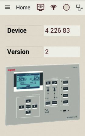
Automatic transfer switch
    4 226 83

    EN   ENGLISH                                                                                     3

                                                                                                DE
                                                                                        MO

                                                                          D             ST
                                                                      AN       TE
                                                               MM
                                                             CO

                                                                                        T
                                                                                   AU

                                                                  E   2
                                                              LIN
                                                        E1                         MA
                                                                                            N
                                                  LIN

                                                                      Q2           OF
                                                                                            F
                                                                                            T
                                                                                     SE
                                                                                   RE

                                              N
                                          TIO     Q1              OSE
                                      VIGA                   CL
                                    NA
                                                       EN
                                                   OP                              CO
                                                                                        M
                                                                              IR

                               OK
                            NU
                          ME

2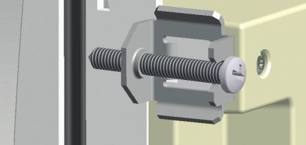
Installation and user manual
                                                                                     Automatic transfer switch
                                                                                                     4 226 83

      WARNING
• Read carefully the manual before the installation or use, taking count of the informations of instruction sheet given
  with to the product.
• These equipments have to be installed by qualified personnel, in compliance to local standards, to avoid damages or
  safety hazards.
• Before any device maintenance operation, remove the supply from measuring inputs or isolate them cutting the supply
  from other sources.
• Legrand assumes no responsibility if the device isn’t properly used, if installative informations aren’t respected or if the
  device is tampered.
• Products described here below are subject to alterations and changes without prior notice. For this reason the catalo-
  gues data couldn’t have contractual value.
• Clean the instrument with a soft dry cloth; do not use abrasives, liquids.
• Due of presence of electrical connections, the safety standards have to be respected.
• The ATS is supplied with Legrand standard parameters. These couldn’t respect the necessity of the specific application/
  installation. For this reason it is necessary to know the parameters and eventually to modify them in order to better
  integrate the device to the plant.

       SAFETY INSTRUCTIONS
This product should be installed in compliance with installation rules, preferably by a qualified electrician. Incorrect installation
and use can lead to risk of electric shock or fire.
Before carrying out the installation, read the instructions and take account of the product’s specific mounting location.
Do not open up, dismantle, alter or modify the device.
All Legrand products must be opened and repaired exclusively by personnel trained and approved by Legrand. Any unauthori-
zed opening or repair completely cancels all liabilities and the rights to replacement and guarantees.
Use only Legrand brand accessories.

                                                                                                                                   3
Index
1. General features 6
1.1 Description 6
1.2 Applications 6
1.3 Installation 6
2. ATS front panel description 7
2.1 Identification of ATS check and management area 7
3. Operating mode 10
3.1 Reset mode (OFF-RESET) 10
3.2 Manual mode (MAN) 10
3.3 Automatic mode (AUT) 13
3.3.1 Control of 2 lines and 1 tie breaker QC (2 lines and 3 devices) - Standard 13
3.3.2 Logic type C: 2S – 1T – SI Standard Legrand (Default) 13
3.3.3 Logic type B:2S-1T-PL 14
3.3.4 Logic type D: 2S – 1T – AI 14
3.3.5 Logic type O: 2S-NPL 15
3.3.6 Control of 2 lines and 2 changeover devices 15
3.3.7 “Open transition” changeover: 16
3.3.8 “Closed transition” changeover 18
3.4 Test mode (TEST) 20
4. Power-up 21
5. Main menu 21
6. Password access 22
7. Table of display pages 24
8. Expandability 27
9. Communication 33
9.1 Limit thresholds (LIMx) 30
9.2 Remote-controlled variables (REMx) 30
9.3 User Alarms (UAx) 30
9.4 Counters (CNTx) 31
9.5 PLC Logic (PLCx) 31
9.6 Timers (TIMx) 31
10. Keypad lock 31
11. Programmation 32
11.1 Parameter setting (setup) from frontal panel 32
11.2 Parameter setting (setup) with PC 32
11.3 Parameter setting with smartphone or tablet 33
11.4 IR port 33
12. Generator test 34
12.1 Generator command with simulation of line missing 34
4Installation and user manual
Automatic transfer switch
4 226 83
13. Parameters 36
13.1 Description of “Utility” menu 36
13.2 Description of “General” menu 37
13.3 Description of “Password” menu 38
13.4 Description of “Battery” menu 39
13.5 Description of “Acoustic alarms” menu 40
13.6 Description of “Source Lines (S.Qn)” menu 40
13.7 Description of “Breakers” menu 41
13.8 Description of “Switch” menu 42
13.9 Description of menu “Source line control S.Qn ” 44
13.10 Description of “Communication” menu 46
13.11 Description of “Automatic Test” menu 47
13.12 Description of “Digital inputs” menu 48
13.13 Description of “Programmable outputs” menu 48
13.14 Description of “Miscellaneous” menu 49
13.15 Description of “Limit thresholds” menu 49
13.16 Description of “Counters” menu 50
13.17 Description of“Timer” menu 51
13.18 M19 Description of “Analog inputs” menu 51
13.19 M20 Description of “ Analog outputs ” menu 51
13.20 Description of “User alarms” menu 51
13.21 Description of “Alarms” menu 52
13.22 Alarm properties 52
13.23 Alarm table 53
13.24 Alarm description 53
14. Function I/O 56
14.1 Programmable inputs function table 53
14.2 Default programmable inputs 58
14.3 Output function table 58
14.4 Default programmable outputs 59
15. Commands menu 60
16. Installation 61
17. Terminals position 61
18. Dimensions 61
19. Technical characteristics 62
51. General features
The automatic transfer switch ref. 422683 has been designed to control and to manage the automatic changeover be-
tween two power sources with the followings setups:
• Line–Line (U-U)
• Line–Generator (U-G)
• Generator–Generator (G-G)
The ATS can command and control up to three devices (breakers or contactors): two to manage lines and one to manage
the tie breaker.
ATS has an LCD screen to provide a clear and intuitive user interface.
1.1 Description
• 128x80 pixel, backlit LCD screen with 4 grey levels.
• 8 language texts for measurements, settings and messages.
• Fully user-definable alarm properties.
• 100-240VAC power supply.
• Aux supply available at 12-24-48 VDC.
• 2 measure voltages inputs (Three-phases+neutral).
• Voltage thresholds with programmable hysteresis.
• Integrated isolated RS-485 Interface.
• Front optical programming interface, galvanically isolated, connectable with USB and WiFi dongles.
• 8 programmable digital inputs (negative).
• 7 outputs:
- 2 relays with NO contact 12A 250VAC.
- 2 relays with NO contact 8A 250VAC.
- 3 relays with changeover contact NO/NC 8A 250VAC.
• Storage of the last 250 events.
• IP 65 front protection.
• Compatible with App and SW ACU.
1.2 Applications
• To check and to manage lines: line-line (U-U), line-generator (U-G) and generator-generator (G-G).
• Possibility to switch the load in “open transition” (default) or “close transition” modes.
• Control of three-phase, two-phase and single-phase networks.
• Control of phase-phase and / or phase-neutral voltages.
• 5 logics to control 2 lines with tie breaker systems.
• To control 2 lines in “open transition” modality.
• To control 2 lines in “close transition” modality.
• Possibility to choose the kind of sources (line or generator) and its priority for all scenarios.
• Manage of not-priority loads.
• Control of motorized circuit breakers or contactors.
• Control of undervoltage, overvoltage, phase loss, asymmetry, minimum frequency, maximum frequency.
• Possibility to manage custom logic using ladder PLC language (50 lines for 8 columns).
1.3 Installation
• Install the unit following the instruction sheet attached to the product. Evaluate if the default configuration is in com-
pliance with the desired one. Otherwise it is necessary modify the configuration. Check the wiring diagram supplied by
Legrand in order to correctly connect the unit and others Legrand devices.
• The ATS standard configuration guarantees the correct work of devices if wiring diagrams supplied are respected.
WARNING
the change of parameters, of input functions, of output functions etc... causes a functional change. This could
cause incompatibility with standard wiring diagrams. It is recommended to evaluate changes of parameters or
functional modes after having read the ATS user manual.
• At first power on, the OFF/RESET mode is activated on the ATS.
6Installation and user manual
Automatic transfer switch
4 226 83
2. ATS front panel description
2.1 Identification of ATS check and management area
1= LCD Display
2= Command area
COMMAND MODE
TEST
LINE 1 LINE 2
AUT
NAVIGATION 3= Selection of ATS
MAN work mode
Q1 Q2
OPEN CLOSE OFF
OK RESET
MENU
5= IR Port
IR COM
6= Alarm LED
4= Navigation
N.B. If the LED is on, the relative function is activated.
1 = LCD Display
The LCD display allows to see all informations/parameters of ATS. It is possible to have the direct control of changeo-
ver system status with synoptic that provides clear and in real time information about the status of lines and devices.
Fig. 1- LCD Display
72. ATS front panel description
2 = Command area (available in MAN modality)
Keys > – Breaker selection
for manual control of Q1 – Q2 – QC
COMMAND MODE
TEST
LINE 1 LINE 2
LINE 1 voltage presence LED (green) LINE 2 voltage presence LED (green) –
AUT
It indicates that line 1 (S.Q1) voltage is it indicates that line 2 (S.Q2) voltage is
within the set limits. within the set limits.
NAVIGATION
MAN
Breaker Q1 state LED (yellow) Breaker Q2 state LED (yellow) –When
Q1 Q2
When fixed, it indicates the open or fixed, it indicates the open or closed state of
closed state of Q1. When blinking, it Q2. When blinking, it indicates incoherence
indicates incoherence between required OPEN CLOSE between
OFF required state of the ATS and real
state of the ATS and real state detected state detected by the feedback signal.
OK RESET
by the feedback signal.
MENU
OPEN key CLOSE keys
Manual command to open breakers. Manual command to close breakers.
IR COM
N.B.1 If the LED is on, the relative function is activated.
N.B.2 For QC device (tie breaker) LED indications about status of command and open/close status aren’t available.
Anyway it is possible to read from display the status open/close of QC .
Fig. 2 - QC close ( I ) Fig. 3 - QC open ( O )
It is recommended to bring on front panel the signal of open/close of breakers Q1, Q2 and in particular QC using OC
auxiliary contacts (open/close).
3= Selection of ATS operating mode
TEST LED COMMAND MODE
It indicates the TEST mode active. OFF button
It selects the OFF operating mode.
TEST
AUT LED
It indicates the AUT mode active. AUT button
LINE 1 LINE 2
It selects the AUT operating mode.
AUT
MAN LED
It indicates the MAN mode active. MAN button
NAVIGATION
It selects the MAN operating mode.
MAN
Q1 Q2
OFF/RESET LED
It indicates the OFF/RESET mode active. OFF/RESET button
It selects the OFF/RESET operating mode.
OPEN CLOSE OFF
OK RESET
MENU
N.B. If the LED is on, the relative function is activated. IR COM
8Installation and user manual
Automatic transfer switch
4 226 83
COMMAND MODE
TEST
LINE 1 LINE 2
4= Navigation
AUT
NAVIGATION
MAN
Q1 Q2
COMMAND MODE
OPEN CLOSE OFF
TEST
OK Key OK ✓ – To recall the main
RESET
Key , , , – For scrolling
the display and selecting
MENU menu and to confirm a selection.
LINE 1 LINE 2
menu options.
AUT
IR COM
NAVIGATION
MAN
Q1 Q2
5 = IR Port OPEN CLOSE OFF
OK RESET
MENU
IR Port
IR COM
Connecting IR port to connect IR-USB or IR-WiFi dongle accessories, to allow the dialogue between ATS and SW ACU or
APP ACU.
6 = Alarm LED
If it is flashing, it indicates an active alarm.
93. Operating modes
With of OFF-RESET/MAN/AUT/TEST keys the desidered operating mode can be selected and it will appear on the
display.
It is possible to see the selected mode with LED on ATS frontal.
Fig 4 - OFF/RESET mode Fig. 5 - MAN mode
Fig 6 - AUT mode Fig. 7 - TEST mode
The change of operating mode can be done by pressing the specific button for at least 0.5s. After this time the new cho-
sen modality will appear on the display.
3.1 Reset mode (OFF-RESET)
• In this mode the ATS looks over the lines status but it does not perform any changing actions.
• In OFF/RESET mode, measures display and status LEDs remain active.
• Pressing the OFF-RESET button it’s possible to reset the retentive alarms, after removing alarm conditions.
N.B. To access the programming menu is necessary to activate the OFF mode.
3.2 Manual mode (MAN)
• In MAN mode it is possible to electrically command the devices Q1, Q2 and QC directly from the ATS.
COMMAND MODE COMMAND MODE
TEST TEST
LINE 1 LINE 2 LINE 1 LINE 2
AUT AUT
NAVIGATION NAVIGATION
MAN MAN
Q1 Q2 Q1 Q2
OPEN CLOSE OFF OPEN CLOSE OFF
OK OK RESET RESET
MENU MENU
• The command can be selected independently IR COM
from lines status. If in presence of auxiliary
IR COM
voltage necessary to electric
command, it can be done only if it respects the chosen functional logic. The ATS continuously checks, in fact, that the
provided command is in compliance to breakers status (Q1 – Q2 – QC) and to functioning logic table chosen for the
plant. If the command is not coherent, it will be discarted.
10Installation and user manual
Automatic transfer switch
4 226 83
• The command of changeover devices, in Legrand Default configuration, is continuos. The user can set the kind of com-
mand modifying the parameter P07.n.06 (using the layout with three devices, it is recommended to use the continuos
command).
In the Standard configuration, (device with 2 sources (U-U) and 1 tie breaker), logic control is done respecting the follow-
ing table:
TYPE 2 S- 1T -SI
S Q1 S Q2
Type
C
Q1 Q2
S.Q1 S.Q2 Q1 Q2 QC
0 0 0 0 0
QC
0 1 0 1 1
1 0 1 0 1
1 1 1 1 0
Fig 8 - Standard configuration.
2 sources (U-U) and 1 tie breaker
To execute the electric command of devices, it is necessary to enter in MAN mode pressing the correct key. On display the
synoptic page appears and the MAN mode will be indicated.
Fig. 9 - MAN Mode Indication
COMMAND
COMMAND MODE
MODE
Using keys it is TEST
TEST
possible to select of device to command (Q1, Q2, QC).
The selection of devices is possible in the following order:
LINE
LINE
1 1 LINE
LINE
2 2
Q1>>Q2>>QC and vice versa QC3. Operating mode
Fig. 10 - Selection of device order Q1>>Q2>>QC
Fig. 11 - Selection of device order QCInstallation and user manual
Automatic transfer switch
4 226 83
3.3 Automatic mode (AUT)
• In automatic mode, the ATS checks permanently the lines and breakers status. Starting from the status of lines S.Q1 and
S.Q2, it performs autonomously the closing/opening operations of breakers Q1, Q2 and, in function of command logic
chosen, it manages the command of tie breaker QC and the optional startup/shutdown of the generator set.
• When the main line (S.Q1) exceeds the specified limits for a time higher than the one set, the green LED (line presence)
switches off giving a “threshold out” alarm. The ATS disconnects the load from S.Q1 and connects it to the S.Q2 (if it is
available and within admitted limits) closing also the QC. After S.Q1 returns within the specified thresholds, the ATS
moves the load on this one after it has checked the stability and the quality of line and it opens the QC.
• During the transfer operations with tie breaker QC, the device Q2 stays closed assuring the service continuity of load.
• The automatic functioning cycles are different in relation of kind of logic applied.
The programmables logics control are the following:
• Control of 2 lines and 1 tie breaker (2 lines and three devices - Default)
2S - 1T SI Standard Legrand
2S - 1T-PL
2S - 1T-PL
2S - 1T –AI
2S - NPL
• Control of 2 lines and 2 devices in “open transition” mode
• Control of 2 lines and 2 devices in “closed transition” mode
For each logic it is possible to choose the kind of lines control selectioning the mode U-U, U-G, G-G, establishing if the
command is related to motor breakers or contactors and defining the line priority.
3.3.1 Control of 2 lines and 1 tie breaker QC (2 lines and 3 devices) - Standard
The ATS in standard configuration is able to control 2 lines U-U (Utility - Utility) and 1 tie breaker. This kind of control can
be modified in case of necessity to associate a generator.
It is possible to select different kinds of control in function of plant requirements.
It is possible to bring some changes passing from a control U-U to U-G or G-G. To do this is enough to modify the parame-
ter of line to control, to activate the extended programmables outputs with external modules to control generator.
In the followings tables are shown the different logics:
3.3.2 Logic type C: 2S – 1T – SI Standard Legrand (Default)
With this logic it is possible the control of 2 sources S.Q1 and S.Q2 supplied from transformers or generics lines. The sourc-
es characteristics have to allow the contemporary power supply of Load 1 and Load 2. Using this logic, it is possible to
supply loads from a single source closing a line breaker Q1 or Q2 and the tie breaker QC.
LINES Type C: 2S – 1T - SI SQ1 SQ2
S.Q1 S.Q2 Q1 Q2 QC Load 1 Load 2
0 0 0 0 0 OFF OFF Q1 Q2 Q
0 1 0 1 1 ON ON
1 0 1 0 1 ON ON
1 1 1 1 0 ON ON
QC
Q
Load 1 Load 2
133. Operating mode
Others possible control logics can be chosen modifying parameters of menu M02 “General” P02.01.
The followings logics of control can be chosen:
• Manage of 2 power sources using 3 devices
• Manage of 2 power sources using 2 devices
When the logic of control is modified, it is necessary to check the correct modifies and cabling schema.
3.3.3 Logic type B:2S-1T-PL
Control of 2 power sources with 2 independent loads (Load 1 e Load 2) that, in normal conditions, are supplied from S.Q1
and tie breaker QC.
In case of missing of S.Q1, S.Q2 can supply the only Load, otherwise, in case of missing of S.Q2 it is possible to supply both
loads with S.Q1 and the closing of tie breaker QC.
LINES Type B: 2S-1T-PL SQ1 SQ2
S.Q1 S.Q2 Q1 Q2 QC Load 1 Load 2
0 0 0 0 0 OFF OFF Q1 Q2 Q
0 1 0 1 0 OFF ON
1 0 1 0 1 ON ON
1 1 1 0 1 ON ON
QC
Q
Load 1 Load 2
3.3.4 Logic type D: 2S – 1T – AI
Control of 2 power sources with 2 independent loads (Load 1 and Load 2) that, in normal conditions, are supplied from
the related source S.Q1 and S.Q2.
In case of missing of S.Q1, S.Q2 can supply the only Load 2, otherwise in case of missing of S.Q2, Load 1 and Load 2 can be
supplied from S.Q1 and the closing of QC.
LINES Type D: 2S – 1T - AI SQ1 SQ2
S.Q1 S.Q2 Q1 Q2 QC Load 1 Load 2
0 0 0 0 0 OFF OFF Q1 Q2 Q
0 1 0 1 0 OFF ON
1 0 1 0 1 ON ON
1 1 1 1 0 ON ON
QC
Q
Load 1 Load 2
14Installation and user manual
Automatic transfer switch
4 226 83
3.3.5 Logic type O: 2S-NPL
Control of 2 power sources with 2 independent loads (Load 1 and Load 2) that, in normal conditions, are supplied from S.Q1.
In case of missing of S.Q1, S.Q2 can supply only the Load 2 with Q2.
In case of presence of both S.Q1 and S.Q2, the priority of supply of Loads is of S.Q1 with Q1 and QC.
LINES Type O: 2S-NPL
SQ1 SQ2 SQ1 SQ2
S.Q1 S.Q2 Q1 Q2 QC Load 1 Load 2
0 0 0 0 0 OFF OFF
Q1 Q2 Q1 Q2 Q1
0 1 0 1 0 OFF ON
1 0 1 0 1 ON ON
1 1 1 0 1 ON ON
QC
QC
Load 1 Load 2 Load 2
Load 1
3.3.6 Control of 2 lines and 2 changeover devices
The ATS can control 2 power sources S.Q1 and S.Q2 and control the changeover of them using devices Q1 and Q2.
In this configuration the ATS can manage the changeover in “open transition” or “closed transition” modes.
These different modes of control require different setup of changeover system.
Open transition Closed transition
SQ1 SQ2 SQ1 SQ2
Q1 Q2 Q1 Q2
Load Load
153. Operating mode
3.3.7 “Open transition” changeover:
The logic of control and changeover in mode “open transition” respects the general rules of switch between two lines. This
command logic provides to open the device of not commanded line and after the closing of commanded line. The same
logic of command is applied when the priority line comes back.
It is possible to apply this logic to systems U-U, U-G and G-G.
The advantage of this kind of management is to have possibility to mechanically interlock breakers and to avoid the tem-
porary closing (also manually of both lines on the load).
Main line Secondary line
230/400 V 230/400 V
N R S T N R S T
Q1 Q2
OC1
OC1
CTR
CTR
CC M CC M
Motor Auxiliary Motor Auxiliary
Operator contact Operator contact
LOAD
Here it is shown the working logic in mode “open transition” with ATS in AUT and MAN modes.
16Installation and user manual
Automatic transfer switch
4 226 83
With this mode, the switching of load from a line (S.Q1) to the other line (S.Q2) or viceversa can happen with a voltage
breaking.
S Q1
S Q1
GE S Q2
GE S Q2
S Q1
ON
Q1
OFF
ON
GE S Q2
Q1 ON
Q2 OFF
ON OFF
ON
Q1
OFF Q2
ON OFF
Q2
OFF
SQ1 GE SQ1 GE SQ1 GE
GE GE GE
SQ1 GE SQ1 SQ1 GE GE SQ1 SQ1 GE GE SQ1 GE
O I I O I O
GEQ1 Q2 GE Q1 Q2 Q1 Q2
GE GE GE GE
O I I O I O
Q1
O
Q2 Q1
I Q2
I Q1
O Q2
I O
Q1 Q2 Q1 Q2 Q1 Q2
Complete sequence of changeover from grid to generator and reverse:
SQ1 GE SQ1 GE SQ1 GE SQ1 GE SQ1 GE SQ1 GE
SQ1 GE SQ1 GE SQ1 GE SQ1 GE SQ1
GE GE GE GE GE GE
GE GE GE GE
I O O O O I O I O O I O
SQ1 GE SQ1 GE SQ1 GE SQ1 GE SQ1
Q1 I
Q2 Q1 O Q2 O Q1 O
Q2 Q1 O Q2 I Q1 O Q2 Q1 I O Q2
Q1 GE
Q2 Q1 GE
Q2 Q1 GE
Q2 Q1 GE
Q2 Q1
I O O O O I O I O
Q1 Q2 Q1 Q2 Q1 Q2 Q1 Q2 Q1
173. Operating mode
3.3.8 “Closed transition” changeover
N.B. The “closed transition” (see parameter P.08.14 of menu M08 “switch”) control logic can be used only with ATS
in AUT mode (automatic control of sources and devices). If the ATS is switched in MAN mode (electric command
of breakers from ATS), it works following the “open transition” logic. The same behaviour is present passing from
AUT to OFF/RESET mode.
The logic of command and control of two lines for the changeover in “closed transition” is used to reduce to minimum the
interruptions of energy. This logic allows to avoid the second interruption of energy during the changeover between sec-
ondary line (generator) to primary line (grid). Generally it is applied in changeover system type (U-G). In case of blackout
of primary line, the relative breaker is opened and the starting command of generator on secondary line is given. After the
secondary line (generator) is available, the breaker Q2 will be closed and the load is supplied from S.Q2.
When the primary line is available again, the ATS waits that all parameters of voltage, frequency and phases synchronism
are correct and it commands the closing of Q1. The breaker Q2 will remain anyway close for a configurable time. After, the
changeover is completed opening Q2. For a short period, the load is supplied from net and generator in parallel.
For this application it is MANDATORY to have specific generators capable to self regulate in order to guarantee
that 2 lines are in perfect synchronism.
N.B. For this application, the mechanical interlock HAVE NOT TO BE INSTALLED to permit the contemporary
closing of the lines.
Main line Secondary line
230/400 V 230/400 V
N R S T N R S T
Q1 Q2
OC1
OC1
CTR
CTR
CC M CC M
Motor Auxiliary Motor Auxiliary
Operator contact Operator contact
LOAD
Here it is represented the working logic in mode “closed transition” with ATS in AUT mode.
18Installation and user manual
Automatic transfer switch
4 226 83
In the sector A the syncronization of lines is verified and in the sector B the closing of both lines in parallel is done (closed
transition): S Q1 A B
GE S Q2
S Q1 A B
S Q1 A B
ON
GEQ1 S Q2
GE S Q2 OFF
ON
ON
Q2 ON
Q1
Q1OFF
OFF OFF
ON ON
Q2 Q2
OFF
OFF
SQ1 GE SQ1 GE SQ1 GE
GE GE GE
SQ1 GE SQ1 GE SQ1 GE
O I I I I O
GE GE GE
Q1 Q2 Q1 Q2 Q1 Q2
O I SQ1I GE I I SQ1 O GE SQ1 GE
Q1 Q2 Q1 Q2 Q1 Q2
GE GE GE
O I I I I O
Q1 Q2 Q1 Q2 Q1 Q2
Complete sequence of changeover from grid to generator in “closed transition”
SQ1 GE SQ1 GE SQ1 GE SQ1 GE SQ1 GE SQ1 GE SQ1 GE
SQ1 GE SQ1 GE SQ1 GE SQ1 GE SQ1 GE
GE GE GE GE GE GE GE
I O O O GE
O I O GE I I GE I I GEO I O GE
Q1 Q2 Q1 Q2 Q1 Q2 Q1
I O O O OQ2 Q1
I Q2
OQ1 Q2
I Q1
I Q2
I
Q1 Q2 Q1 Q2 Q1 Q2 Q1 Q2 Q1 Q2
SQ1 GE SQ1 GE SQ1 GE SQ1 GE SQ1 GE
GE GE GE GE GE
I O O O O I O I I I
Q1 Q2 Q1 Q2 Q1 Q2 Q1 Q2 Q1 Q2
Here it is represented the operating logic “closed transition” mode with ATS in MAN mode.
193. Operating mode
With this mode, as the control of lines syncronization can’t be done, it is not possible to manage the simultaneous closing
of lines. It is mandatory toSapply
Q1 the “open transition” logic.
GE SS Q2
Q1
S Q1
ON
GE S Q2
GE S Q2 Q1
OFF
ON ON
Q1 Q1
Q2
OFF
OFF
ON
ON
Q2
OFF Q2
OFF
SQ1 GE SQ1 GE SQ1 GE
SQ1 GE SQ1 GE SQ1 GE
GE
GE GE GE
GE GE
O I O I I O I I OO I O
Q1 Q2Q1SQ1 Q1 GE
Q2 Q2 SQ1
Q1 Q1
GEQ2
Q2 Q1
SQ1 GE
Q2
GE GE GE
O I I O I O
Q1 Q2 Q1 Q2 Q1 Q2
Complete sequence of changeover from grid to generator and viceversa in MAN mode.
SQ1 GE SQ1 GE SQ1 GE SQ1 GE SQ1 GE SQ1 GE
GE GE GE GE GE GE
I O SQ1 O GE O OSQ1 I GE O SQ1 I O
GE SQ1O I GE O SQ1
Q1 Q2 Q1 Q2 Q1 Q2 Q1 Q2 Q1 Q2 Q1 Q2
GE GE GE GE
I O O O O I O I O
SQ1 GE SQ1 GE SQ1 GE SQ1 GE SQ1
Q1 Q2 Q1 Q2 Q1 Q2 Q1 Q2 Q1
GE GE GE GE
I O O O O I O I O
3.4 Test mode (TEST)
Q1 Q2 Q1 Q2 Q1 Q2 Q1 Q2 Q1
• In test mode, the equipment starts the generators, if present, to test their operation. If the TEST button is held pressed
for 5 seconds, the equipment will run a cycle which simulates loss of the priority line anticipated by a notification mes-
sage with consequent load transfer.
This will momentarily interrupt power supply to the load.
20Installation and user manual
Automatic transfer switch
4 226 83
4. Power-up
• The ATS can be supplied at 100-240VAC o 12-24-48VDC. In case of simultaneous presence of both power supplies, pri-
ority is given to the AC power supply.
• After first power-up the device normally starts in OFF/RESET mode.
• During the normal work of ATS, if it switches off, when it will be switched on it comes to operating mode actives before
the switching off.
If it is necessary to modify this behaviour, the parameter P01.03 in the M01 “utilities” menu has to be changed.
• The automatic transfer switch can be supplied with a second Vaux with the input “DC battery” from 12VDC to 48VDC.
The same input could be used for the battery control, if it is activated. In this case it is necessary to set the correct bat-
tery voltage in the menu M04 “battery”.
• During power-up all the LEDs blink in order to verify their operation.
5. Main menu
• The “main menu” is made up of a group of graphic icons that allow to access to functions. In function of selected icon,
a description will appear on the display.
Fig. 14 - Main menu
• The main menu allows the quick access to measurements and settings.
• Starting from main page, press ✓ OK. The menu screen is displayed.
• Press or to rotate clockwise/counter clockwise to select the required function. The selected icon is highlighted
and the central part of the display shows the description of the function.
• Press (AUT) ✓ OK to activate the selected function.
• If some functions are not available, the correspondent icon will be disabled (shown with light grey colour).
• Icons descriptions:
Password access Synoptic L-L voltages
Commands menu Alarm status
Parameters Setup Nominal data
Information page Statistics
Input/output status
Battery status Event log
Fig. 15 - Icon desctription
•• – Settings and access to the password inserction.
•• – View of voltages.
•• – View of voltages.
•• – View of alarm status.
•• – Access point to nominal data.
•• – Access point to the statistic data of the ATS operation.
•• – Access point to the event log list.
•• – Access point to view of input/output status.
•• – Input/output status.
•• – Access point to information page.
•• – Access point to the setup menu for parameter programming (see dedicated chapter).
•• – Access point to the “commands menu (see dedicated chapter).
216. Password access
• The ATS has a password function that at first switching on is not active in order to access to all parameters (Password
OFF).
N.B. In case of password activation/modify, it is recommended to make a copy of it to guarantee future access
with desired rights.
• It is possible to define different level of password in order to permit different access to “settings/commands” menu in
function of access rights.
• If password is activated, in order to enter to protected data, it is necessary to insert the correct code.
• To enable password management and to define numeric codes, see M03 “password” menu.
• There are different access levels:
• Password disabled (OFF)– The password is disabled. Complete access to all parameters (Legrand Default).
• Password enabled (ON) – The password is enabled:
- Access without to insert password (Lev.1)- The password is enabled but not inserted. This access allow the
visualization only.
- User Level access (Lev.2)- It allows the change of mode, the clearing of recorded values and editing of a limited
number of setup parameters.
- Advanced Level access (Lev.3) - Complete access to all parameters.
Password OFF
MENU Password ON (lev2-lev.3)
NO Password Lev 1 Lev. 2 Lev. 3
M01 ● X ● ●
M02 ● X X ●
M03 ● X X ●
M04 ● X X ●
M05 ● X X ●
M06 ● X X ●
M07 ● X X ●
M08 ● X X ●
M09 ● X ● ●
M10 ● X ● ●
M11 ● X ● ●
M12 ● X X ●
M13 ● X X ●
M14 ● X X ●
M15 ● X X ●
M16 ● X X ●
M18 ● X X ●
M19 ● X X ●
M20 ● X X ●
M21 ● X X ●
M22 ● X X ●
• Passwords for menu 19 and 20 are only for custom solution: for further info please contact Legrand.
• The default passwords for each level are the following:
Password OFF default Legrand Level Password
Password OFF (Default) -
1 -
Password ON 2 1000
3 2000
• From normal viewing, press ✓ OK to recall main menu, select the password icon and press ✓ OK.
22Installation and user manual
Automatic transfer switch
4 226 83
Fig. 16 - Enter password
• With keys and it is possible to change the selected digit.
• With keys and it is possible move through the digits.
ATTENTION! To confirm the password it is mandatory to select icon and to confirm with ✓ OK.
If the code is confirmed with OK without going on key icon “ ”, the value won’t be accepted.
• In function of level password “Level 2-User or Level 3-Advanced” the correspondant unlock message is shown.
• Once unlocked the password, the access rights are valid until one of the followings conditions are verified:
- A timeout period of two minutes elapses without any keystroke.
- The device is reset (after quitting the setup menu).
- The device is turned off.
• To quit the password entry screen press ✓ OK key.
237. Table of display pages
• Keys and allow to scroll pages of measures.
• Some measures could not be available in function of ATS programming.
Example: if the function “limits” isn’t set, the related page can’t be available.
• The user has the possibility to specify the page shown on display after a time during that anyone press keys. Fur-
themore the ATS can be programmed so that the display always remains in the position where it was left. To do this, see
menu M01 “utility”.
• In default conditions, the main page of display represents the synoptic of plant that can be modified using parameter
P02.01.
• In the synoptic there are all informations that, with status of LEDs, allow to have a complete knowledge of power sourc-
es status.
• Here below are represented an example of synoptic on display:
Fig. 17 - Synoptic
• The following table contains the details of display pages.
Voltage 1 Voltage 2
(line SQ1) (line SQ2)
Contacts status Contacts status
(breaker Q1) (breaker Q2)
Contacts status
Fig 18 - Synoptic (tie breaker QC)
Fig 19 - Date / Time
Fig 20 - Phase to phase voltage
Voltage
Frequency
Fig 21 - Phase voltage
24Installation and user manual
Automatic transfer switch
4 226 83
Active alarms
Fig 22-Alarms
Voltage
thresholds
Frequency
thresholds
Fig 23-Control thresholds
LINE1 LINE 2
AUT mode commutation counter AUT mode commutation counter
MAN mode commutation counter MAN mode commutation counter
Alarms counter A03 A04 Alarms counter A03 A04
Time lapse with load supplied Time lapse with load supplied
Time lapse with lines in the limits Time lapse with lines in the limits
Time lapse with lines out the limits Time lapse with lines out the limits
Total time with no supplied load
ATS total power down counter
Fig. 24 - Statistics
Minimum voltage Maximum voltage
measured measured
Actual voltage Maximum voltage limit
Minimum MAX and min
voltage limit voltages reset
Fig. 25 - Battery status
Fig. 26 - Expansion modules
257. Table of display pages
Fig. 27-I/O Status
Fig. 28 - Input configurations
Fig. 29 - Outputs configurations
Fig. 30 - Info page
ATS name
Revision
Software
Hardware
Fig. 31 - System info
26Installation and user manual
Automatic transfer switch
4 226 83
8. Expandability
• The automatic transfer switch can be expanded with additional modules.
It is possible to connect a maximum of 3 expansion modules at the same time.
Fig. 32 - Expansion modules
• The expansion modules provide additional resources in order to extend the checking and managing chances. These
ones can be parameterized and managed through the dedicated setup menus.
• The supported expansions modules can be grouped in the following categories:
- I/O modules
• Procedure to add an expansion module:
- remove the power supply to automatic transfer switch (230VAC and auxiliary in DC, if present);
- remove the protecting cover of one of the expansion slots;
- insert the upper hook of the module into the fixing hole on the left of the expansion slot;
- rotate right the module body, inserting the connector on the bus;
- push until the bottom clip snaps into its housing.
• Unless otherwise indicated, the insertion order of the modules is free.
• Fit the specific module lock accessory included in the package to improve expansion module fixing safety in applica-
tions subjected to strong vibrations.
• To fit this accessory:
- remove the two right screws with a Torx T7 screwdriver
- Set the jumper over the previously coupled modules
- fasten the screws back in their original seat.
• Once expansion modules are installed, the ATS recognize them when it will be powered on. It automatically recognises
the kind of mounted expansions modules showing it on display.
• At switching on, if the device configuration has changed compared to the last saved, (one module has been added
or removed), the ATS asks the user to confirm the new configuration. In case of confirmation, the new configuration
will be saved and will become effective, otherwise the mismatch will be shown at every subsequent power-on of the
system.
Figura 33 - Configuration change
N.B. One time the module has been installed, the associated functions have to be set by the user.
278. Expandability
• The I/O numbering is shown under each module.
• The I/O status (active/not active) is graphically shown in the following way:
- ACTIVE: with words in negative (white on black background)
- NOT ACTIVE: with words in positive (black on white background)
Fig. 34- I/O Active/Not active
• The setup menus related to the modules are always accessible, even if the expansion modules are not physically fitted.
• It is possible to add modules I/O of the same type; the setup menus are multiple and identified by a sequential number.
• The following table shows how many modules of each group can be mounted at the same time.
MODULE TYPE CODE FUNCTION MAX Nr.
COMMUNICATION Standard
4 226 90 4 STATIC OUTPUTS 3
I/O 4 226 91 2 CHANGEOVER RELAYS 3
4 226 92 2 INPUTS + 2 RELAYS NO 3
* maximum 3 for ATS indipendently from the type
28Installation and user manual
Automatic transfer switch
4 226 83
9. Communication
• Into menu “communication” M10 it is possible set COM channel
• The ATS has an integrated communication port RS-485 (COM1).
• The inputs and outputs are identified by a code and a sequence number. Example: the digital inputs are identified by
code INPx, where x is the number of the input. In the same way, digital outputs are identified by code OUTx.
The numeration of input/output is based on mounting position of expansion modules, with progressive numeration
from top to bottom.
• The expansion I/O numbering starts from the last I/O fitted on the base unit. For example, for digital inputs , INP1…
INP12 on the basic unit and thus the first digital input on the expansion modules will be named INP13. The I/O number-
ing is shown in the following table:
CODE DESCRIPTION BASE EXP
INPx Digital inputs 1…6 9…20
OUTx Digital outputs 1…7 11…20
COMx Communication ports 1 -
AINx Analog inputs Only for Legrand custom solution
AOUx Analog outputs Only for Legrand custom solution
• Inputs/outputs can be associated to internal variables (bit) that can be associated between them.
Example: limit thresholds can be applied to detected measures or eventual counter related to an activation or fan input x.
• The following table shows all the internal variables managed by the ATS with their range (number of variables per type).
CODE DESCRIPTION RANGE
LIMx Limit thresholds on measurements 1…16
REMx Variables remotely controlled 1…16
UAx User alarms 1…8
CNTx Programmable counters 1…8
PLCx PLC logic variables 1…32
TIMx Timer 1…8
Functions associated to the inputs are the 6 described in the above table.
• LIMx: internal variable that identifies a limit value set by the user and managed by the ATS. Its status (active or not)
depends by out-of-limits of one measurement set by the user.
• CNTx: internal counters that can count pulses coming from an external source (through a digital input INPx) or the
times that a certain condition has been verified.
Example: defining a limit threshold LIMx as count source, it will be possible to count how many times one measurement
has exceeded a certain limit.
• REMx: it allows the managing of remote variables.
• UAx: it allows the activation and managing of 4 programmable alarms.
• PLCx: management of variables of PLC logic (see dedicated programming manual).
• TIMx: management of timer
299.1 Limit thresholds (LIMx)
• The LIMx thresholds are internal variables whose status depends by out-of-limits of one measurement set by the user.
(example: phase to phase voltage L1-L2 higher than 400V).
• The setting of thresholds value is calculated starting from a base value.
Example: “400 V” adding a multiplicative factor “x 1” 400 x 1 = 400V).
• For each LIM, there are two thresholds: upper and lower.
N.B. The upper threshold must always be set to a value higher than the nominal one and the lower threshold must
always to be set to a value lower than the nominal one.
• The control mode of thresholds can be done in 3 modes:
- MIN function: when the value of selected measure is under lower limit, after the delay set, the threshold will be
activated. When the value of selected measure is over the upper limit, after delay set, the threshold will be restored.
- MAX function: when the value of selected measure is higher than the superior limit, after the delay set, the thresh-
old will be activated. When the value of selected measure is under lower limit, after delay set, the threshold will be
restored.
- MAX+MIN function: when the value of selected measure is under lower limit or over the upper limit, after the delays
set, the threshold will be activated. When the value of selected measure comes back into the limits, the threshold will
be restored (if not retenitive).
• The managing of limit can be done in 2 modes: with memory or without memory. In the first case the reset of the alarm
can be done only manually (retenitive); in the second case the reset of alarm is automatic, if the value comes back into
the limits. The setting can be done using the dedicated command in the “commands” menu.
See setup menu M15 “Limit thresholds”.
Parameter number Current value
Minimum value Maximum value
Previous value
Default value
Fig 35-Limit threshold
9.2 Remote-controlled variables (REMx)
• The automatic transfer switch, with an external supervision software, can activate outputs (OUTx) via Modbus protocol
RS 485 channel. This can be done with remote variables REMx.
9.3 User Alarms (UAx)
• User can set a maximum of 8 programmable alarms (UA1…UA8).
• Conditions that generates the alarm can be different:
- In association of one thresholds LIMX set.
- Activation of digital inputs INPx.
- The same criterion can be used to combine an alarm to complex conditions resulting from the logical Boolean combi-
nation of inputs and thresholds, etc. The PLCx variables will be used in this case.
• For each alarm, the user can define a message that will appear on the alarm page.
• Properties of alarms can be defined by the user in the same way that normal alarms.
• When several alarms are activated at the same time, they are displayed sequentially, and their total number is shown
on the status bar.
• To reset one alarm that has been programmed with latch, use the dedicated command in the “commands” menu.
• For details on alarm programming and definition, refer to setup menu M21 “User alarms”.
30Installation and user manual
Automatic transfer switch
4 226 83
9.4 Counters (CNTx)
• This function allows, by selecting a control channel, to activate a counter (see chapter M16 “counters”).
• It is possible to count:
- Impulses acquired from inputs INPx;
- The numbers of activations of outputs OUTx;
- The overcome of limits LIMx;
- Activation of known variables.
• The description of counters CNTx can be customized with a test of maximum 16 characters.
• The unit of measure of counters Umn can be customized with a test of maximum 6 characters.
9.5 PLC Logic (PLCx)
• ACU Software can be set using a ladder program for creating a PLC internal logic inside the ATS, so as to be able to freely
manage any function necessary for generator accessory applications.
• In the program logic, all the variables managed internally by the ATS can be entered, such as inputs (INPx), threshold
limits (LIMx), remote variables (REMx), controller states (RALx) etc.
• The processing results of the various branches of the ladder logic are stored in internal variables (PLCx), which may
later be used to control the ATS outputs, or as support memories to built a more complex logic or to control the alarms
defined by the user (UAx).
• It is additionally possible to create timers inside the PLC program using the programmable timers of the M17 menu.
• The operation of the logic created with the ladder program may be checked in real time and possible corrected on the
specific ACU software window.
9.6 Timers (TIMx)
• The system includes 8 timer variables, named TIM1..TIM8.
• These variables may be used either in the PLC ladder logic or in combination with the OUTx outputs or in combination
with UAx user alarms.
• Each timer variable has an input which controls it (e.g. a LIMx limit or an INPx inputs etc.). The state of this variable
changes from FALSE to TRUE (ramp up) and the timing variable also changes from FALSE to true but only remains true
for the specified time and then returns FALSE.
• Whenever the input variable becomes false, the TIMx variable also becomes FALSE (this also occurs before the end of
the programmed time) and the time counter is reset to zero.
10. Keypad lock
• The automatic transfer switch keypad can be locked, avoiding not desidered command.
• Once the keypad is locked, it will only be possible to view measures, but not to change operating mode or to operate
in MAN mode on devices. If the icon menu is shown and the keypad is locked, wait 2 minutes to return to main page.
• The activation of keypad lock can be made in the followings ways:
- With a programmable input (activate the function “keypad lock”);
- With frontal keys;
- With SW ACU.
• To lock or unlock the keypad, press key and, while holding it down, press key three times without releasing it at
the end.
Release then key and then press it 5 times, then release both keys.
• When the keypad is locked, the display shows the sentence “KEYBOARD LOCKED”. If the keypad isn’t locked the
display shows the sentence “KEYBOARD UNLOCKED”.
3111. Programmation COMMAND MODE
11.1 Parameter setting (setup) from frontalTEST
panel
• To access to “parameters” menu and to modify them, it is necessary put the ATS in OFF mode, recall the “main” menu
LINE 1 LINE 2
(press simultaneously), select the “setup” menu
AUT
( ) and confirm with (✓ OK).
NAVIGATION
MAN
Q1 Q2
OPEN CLOSE OFF
OK RESET
MENU
IR COM
Fig. 36 - Main menu
• Table shown in the following picture is then displayed
Fig. 37 - Setup menu
• With sliding menus Mxx it is possible to select sub-menus where are present all parameters associated to the function.
• Select the required menu with keys or and confirm with ✓ OK.
• Press OFF to quit and return to the measurement viewing.
N.B. If the icon is not enabled (grey color), it is necessary to check access privileges to modify parameters (see
chapter “passwords”).
11.2 Parameter setting (setup) with PC
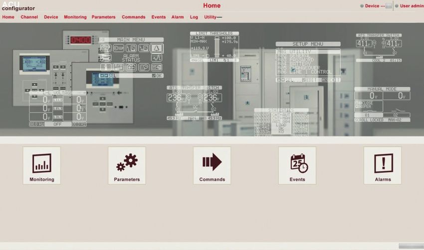
• The managing of setting parameters can be done also using the PC Software “ACU configurator” (available to free
download on Legrand E-catalogue.
• Using software ACU it is possible to transfer set-up parameters from ATS to PC, generating a file. It is also possible to
transfer to ATS a file with parameters from SW ACU.
• It is possible to transfer parameters in 2 ways:
- Total transfer: all parameters are uploaded on ATS in one time
- Partial transfer: only menu with modified data will be uploaded to the ATS
• The PC can be used also to define “information page” where to add informations, charachteristics, data etc...concerning
the application.
Fig. 38 - Software ACU
For more details refers to manual of Software ACU configurator.
32Installation and user manual
Automatic transfer switch
4 226 83
11.3 Parameter setting with smartphone or tablet
• The managing of setting parameters can be done also using the App for smartphone and tablet “ACU configurator”
(available to free download on Google Play and Apple Store).
• The connection between ATS and App is possible with WiFi dongle (Legrand).
• The App permits to see alarms, to send commands, to read measures, to set parameters, to download events.
Fig. 39 - App
11.4 IR port
• The parameters of the automatic transfer switch can be configured and consulted also through the front optical port,
using a USB or WiFi dongle.
• Using this port it is possible to configure and to dialogue with the automatic transfer switch without the need to access
to the rear of the device or having to open the electrical panel. This connection is isolated from internal circuit ensuring
safety for the operator.
• This port guarantees IP65 front protection.
• Simply holding the USB/WiFi dongle up to the front panel, connecting the plugs to the connectors the device will be
connected. The recognition between devices will be shown by the green “LINK” LED on the programming dongle.
3312. Generator test
• The ATS allows to the user to program a periodical control of generator start.
• The automatic test is a periodic test carried out at specific intervals (interval managed on from “setup” menu). This test
can be done only if the ATS is in AUT mode and the function has been enabled.
• It is possible to decide in which days of the week the automatic test can be executed and at what time of the day (hours;
minutes). See menu M11 “automatic test”.
• If there are multiple generators in the system, only one is started for each automatic test. The others will be started in
sequence the next time.
• After starting, the generator works for a programmable time after which it stops. The message “T.AUT” appears on the
display before starting.
• The test can be enabled or disabled for each single generator using the parameters of menu M11 and on the Automatic
Test display page without needing to open the setup menu.
- On the Automatic Test page, press and at the same time.
- Select the required generator by pressing and . Enable the test with and disable it with .
- ✓ OK Save and exit the setting.
- The test can be stopped by pressing key OFF - RESET.
12.1 Generator command with simulation of line missing.
• It is possible to simulate the lack of the priority line by SW in order to verify the behavior of the transfer switch system.
• The simulation can be started either using the “commands” menu (command C.24) or via a digital input, for example
connecting it to a key switch, programming the function of the input to the execution of the command C.24.
• The simulation consists in considering the priority line absent for 3 minutes (even if it is actually present). During this
time the main page shows the message “SIMUL xxx” with the countdown of the time.
• The simulation will cause the start of the generator (if present) and a load transfer exactly as in the automatic cycle.
• It is possible to stop the simulation at any time by passing in OFF mode.
N.B. Doing the simulation through commands menu, user must start from the OFF mode (which allows access to the
menu). Once selected and confirmed the C.24 command, exit the command menu. The unit will independently switch to
TEST mode and it starts the simulation.
In the following table are indicated menu available into ATS:
CODE MENU DESCRIPTION
M01 UTILITIES Language, brightness, display pages etc.
M02 GENERAL Characteristic system data
M03 PASSWORD Access code setup
M04 BATTERY Battery parameters
M05 ACOUSTIC ALARMS Control of internal buzzer and external siren
M06 SOURCE LINES (S.Qn) Characteristic source data
M07 BREAKERS (Qn) Characteristic breaker data
M08 SWITCH Load transfer mode
M09 SOURCE LINE CONTROL (S.Qn) Source line acceptability limits n.
M10 COMMUNICATIONS Communication parameters
M11 AUTOMATIC TEST Period, time, automatic test mode
M12 DIGITAL INPUTS Programmable digital input functions
M13 DIGITAL OUTPUTS Programmable digital output functions
M14 MISCELLANEOUS Functions (maintenance, etc.)
M15 LIMIT THRESHOLDS Programmable limit thresholds
M16 COUNTERS Programmable generic counters
M17 TIMERS Programmable timers for PLC logic
M19 ANALOG INPUTS Contact Legrand
M20 ANALOG OUTPUTS Contact Legrand
M21 USER ALARMS Programmable alarms
M22 ALARMS TABLE Alarm enabling and effect
34Installation and user manual
Automatic transfer switch
4 226 83
• The access to the menu/sub-menu modify page is subject to the input of password (if the function is activated).
• After highlighted the correct menu it is necessary press ✓ OK to show the parameters.
• Each parameter is shown with code, description and actual setting value.
Parameter code Selected parameter
Parameter Present setting value
description
Fig. 40- Battery menu
• To modify the setting of one parameter, select it and then press ✓ OK.
Selected parameter New value entered
Maximum possible
Graph bar of the setting
value-range Factory default
setting
Minimum
possible setting
Fig. 41- setting of Nominal Voltage
• The parameter setting can be modified with and keys. The screen shows the new setting, a graphic bar with the
setting range, the maximum and minimum values, the previous setting and the factory default.
• Pressing and the value is set to the maximum admitted, while with and - it is set to the minimum.
N.B. Pressing simultaneously and , the setting is set to factory default.
During the typing of a text string, keys and are used to select the alphanumeric character while and are used
to move the cursor along the text string.
N.B. Pressing keys and simultaneously will move the character selection straight to character “A”.
• Press ✓ OK to go back to the parameter selection. The entered value is saved.
• Press OFF to save all the settings and to quit the setup menu. The controller executes a reset and returns to normal
operation.
• In “SET-UP” mode, if the user does not press any key for at least 2 minutes, the system leaves automatically and goes
back to normal viewing without saving the changes done on parameters.
3513. Parameters
• In menu “parameters” are described all parameters, their changes and it is defined the work mode of ATS. Menu is com-
posed by 22 parts: from M01 to M22.
• Each menu is composed by specific parameters Px that can be modified in function of needs.
For example, the definition of control characteristics of power sources can be definied by the customer using parame-
ters of M08 “load changeover” menu and M09 “source line control ” menu.
• With menu M09 it is possible to set nominal data for power sources such as nominal voltage, nominal frequency that
could be used to set thresholds.
• The ATS can be set to do voltage checks in three-phases lines with or without neutral, bi-phases or single-phase
(P02.07).
• In case of lines three-phases or bi-phases it is possible to choose if monitor/control phase-phase voltage or phase-neu-
tral voltage or both. (P02.08).
N.B. Nominal voltage set with P02.02 must be referred to phase-phase voltage.
It is possible set a transformation ratio TV associated to the control inputs establishing criteria in M02 “general” menu. In
case a lower voltage is applied but proportional to that of plant, limits of measures will be real values of plant.
13.1 Description of “utility” menu
M01 – UTILITY UoM DEFAULT RANGE
P01.01 Language English English
Italian
French
Spanish
German
Portuguese
Polish
Russian
P01.02 Set real time clock at power-on OFF OFF-ON
P01.03 Power-on operating mode Previous OFF mode
Previous
P01.04 LCD contrast % 50 0-100
P01.05 Display backlight intensity high % 100 0-100
P01.06 Display backlight intensity low % 25 0-50
P01.07 Time to switch to low backlighting s 180 5-600
P01.08 Return to default page s 300 OFF / 10-600
P01.09 Default page Synoptic (page list)
P01.10 Plant identifier (empty) String 20 chr.
• P01.01 – Select display text language.
• P01.02 – Active automatic clock settings access after power-up.
• P01.03 – Start system in OFF mode after power-up or in same mode it was switched off in.
• P01.04 – Adjust LCD contrast.
• P01.05 – Display backlight high adjustment.
• P01.06 – Display backlight low adjustment.
• P01.07 – Display backlight low delay.
• P01.08 – Default page display restore delay when no key pressed. If set to OFF the display will always show the last
page selected manually.
• P01.09 – Default page displayed on power-up and after delay.
• P01.10 – Free text with alphanumeric identifier name of specific plant.
36Installation and user manual
Automatic transfer switch
4 226 83
13.2 Description of “general” menu
M02 – GENERAL UoM DEFAULT RANGE
P02.01 Layout plant C: 2S – 1T - SI A: 2S – 0T
B: 2S – 1T – PL
C: 2S – 1T - SI
D: 2S – 1T – AI
P 2S-NPL
Z: (custom)
P02.02 Nominal plant voltage VAC 400 50÷50000
P02.03 TV Use OFF OFF-ON
P02.04 TV Primary V 100 50÷50000
P02.05 TV Secondary V 100 50÷500
P02.06 Phase sequence control OFF OFF
L1-L2-L3
L3-L2-L1
P02.07 Wiring mode L1-L2-L3 L1-L2-L3-N
L1-L2-L3
L1-N-L2
L1-N
P02.08 Voltage control mode L-L L-L
L-N
L-L + L-N
P02.09 Nominal frequency Hz 50Hz 50 Hz
60 Hz
P02.22 Tie breaker management (QC) Continuous breaker OFF
Pulse breaker
Continuous breaker
Contactor
P02.23 Maximum tie breaker (QC) operation time s 2 1…900
P02.24 Open pulse time s 10 0÷600
P02.25 Close pulse time s 2 0÷600
P02.26 UVR opening pulse time s 1 0.1 … 10.0
P02.27 Delay between UVR and spring load s 0.2 0.1 … 10.0
P02.28 Description of tie breaker QC QC (4 caratteri)
P02.30 Tie breaker (QC) closing delay s 2 0.1…60.0
P02.31 Pre-transfer time load 1 s OFF OFF / 1÷1000
P02.32 Post-transfer time load 1 s OFF OFF / 1÷1000
P02.33 Pre-transfer time load 2 s OFF OFF / 1÷1000
P02.34 Post-transfer time load 2 s OFF OFF / 1÷1000
P02.37 Tie breaker QC continuous control in RESET/ NOC OFF
OFF mode NOC
P02.39 Tie breaker QC conditional enable OFF OFF
INPx
OUTx
LIMx
REMx
PLCx
Ax
UAx
P02.40 Function index (x) 1 OFF/1…99
• P02.01 – Set up the layout of plant.
• P02.02 - Rated voltage of grid and generator. Set the line-to-line voltage for polyphase systems.
37You can also read