System Impact Assessment Report - CONNECTION ASSESSMENT & APPROVAL PROCESS
←
→
Page content transcription
If your browser does not render page correctly, please read the page content below
IESO_REP_0761

            System Impact
        Assessment Report

         CONNECTION ASSESSMENT &
               APPROVAL PROCESS

                                          Final Report

CAA ID:    2011-447
Project:   Grand Bend Wind Farm
Applicant: Grand Bend Wind L.P.

Market Facilitation Department
Independent Electricity System Operator

Date:   December 21, 2011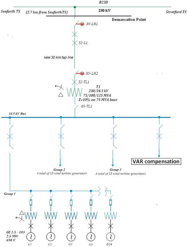
Document ID                    IESO_REP_0761
    Document Name                  System Impact Assessment Report
    Issue                          Final Report
    Reason for Issue               Final Report
    Effective Date                 December 21, 2011

© 2000, Independent Electricity System Operator.
System Impact Assessment Report

        System Impact Assessment Report

        Acknowledgement
        The IESO wishes to acknowledge the assistance of Hydro One in completing this assessment.

        Disclaimers
        IESO
        This report has been prepared solely for the purpose of assessing whether the connection applicant's
        proposed connection with the IESO-controlled grid would have an adverse impact on the reliability of
        the integrated power system and whether the IESO should issue a notice of conditional approval or
        disapproval of the proposed connection under Chapter 4, section 6 of the Market Rules.
        Conditional approval of the proposed connection is based on information provided to the IESO by the
        connection applicant and Hydro One at the time the assessment was carried out. The IESO assumes
        no responsibility for the accuracy or completeness of such information, including the results of
        studies carried out by Hydro One at the request of the IESO. Furthermore, the conditional approval is
        subject to further consideration due to changes to this information, or to additional information that
        may become available after the conditional approval has been granted.
        If the connection applicant has engaged a consultant to perform connection assessment studies, the
        connection applicant acknowledges that the IESO will be relying on such studies in conducting its
        assessment and that the IESO assumes no responsibility for the accuracy or completeness of such
        studies including, without limitation, any changes to IESO base case models made by the consultant.
        The IESO reserves the right to repeat any or all connection studies performed by the consultant if
        necessary to meet IESO requirements.
        Conditional approval of the proposed connection means that there are no significant reliability issues
        or concerns that would prevent connection of the project to the IESO-controlled grid. However, the
        conditional approval does not ensure that a project will meet all connection requirements. In addition,
        further issues or concerns may be identified by the transmitter(s) during the detailed design phase that
        may require changes to equipment characteristics and/or configuration to ensure compliance with
        physical or equipment limitations, or with the Transmission System Code, before connection can be
        made.
        This report has not been prepared for any other purpose and should not be used or relied upon by any
        person for another purpose. This report has been prepared solely for use by the connection applicant
        and the IESO in accordance with Chapter 4, section 6 of the Market Rules. The IESO assumes no
        responsibility to any third party for any use, which it makes of this report. Any liability which the
        IESO may have to the connection applicant in respect of this report is governed by Chapter 1, section
        13 of the Market Rules. In the event that the IESO provides a draft of this report to the connection
        applicant, the connection applicant must be aware that the IESO may revise drafts of this report at any
        time in its sole discretion without notice to the connection applicant. Although the IESO will use its
        best efforts to advise you of any such changes, it is the responsibility of the connection applicant to
        ensure that the most recent version of this report is being used.

Final Report – December 21, 2011                       CAA ID 2011-447
IESO_REP_0761
Hydro One
The results reported in this report are based on the information available to Hydro One, at the time of
the study, suitable for a System Impact Assessment of this connection proposal.
The short circuit and thermal loading levels have been computed based on the information available
at the time of the study. These levels may be higher or lower if the connection information changes
as a result of, but not limited to, subsequent design modifications or when more accurate test
measurement data is available.
This study does not assess the short circuit or thermal loading impact of the proposed facilities on
load and generation customers.
In this report, short circuit adequacy is assessed only for Hydro One circuit breakers. The short circuit
results are only for the purpose of assessing the capabilities of existing Hydro One circuit breakers
and identifying upgrades required to incorporate the proposed facilities. These results should not be
used in the design and engineering of any new or existing facilities. The necessary data will be
provided by Hydro One and discussed with any connection applicant upon request.
The ampacity ratings of Hydro One facilities are established based on assumptions used in Hydro One
for power system planning studies. The actual ampacity ratings during operations may be determined
in real-time and are based on actual system conditions, including ambient temperature, wind speed
and facility loading, and may be higher or lower than those stated in this study.
The additional facilities or upgrades which are required to incorporate the proposed facilities have
been identified to the extent permitted by a System Impact Assessment under the current IESO
Connection Assessment and Approval process. Additional facility studies may be necessary to
confirm constructability and the time required for construction. Further studies at more advanced
stages of the project development may identify additional facilities that need to be provided or that
require upgrading.
CAA ID 2011-447 Final Report – December 21, 2011System Impact Assessment Report Table of Contents
Table of Contents
Table of Contents...................................................................................................... i
Executive Summary ................................................................................................. 1
Project Description ........................................................................................................1
Findings ........................................................................................................................1
IESO Requirements for Connection ..............................................................................2
Notification of Conditional Approval ...............................................................................5
1. Project Description........................................................................................... 6
2. General Requirements ..................................................................................... 7
2.1 Frequency/Speed Control ..................................................................................7
2.2 Reactive Power/Voltage Regulation...................................................................7
2.3 Voltage Ride Though Capability.........................................................................8
2.4 Voltage ..............................................................................................................8
2.5 Connection Equipment Design ..........................................................................8
2.6 Disturbance Recording ......................................................................................8
2.7 Fault Level .........................................................................................................9
2.8 Breaker Interrupting Time ..................................................................................9
2.9 Protection System .............................................................................................9
2.10 Telemetry ........................................................................................................ 10
2.11 Revenue Metering ........................................................................................... 10
2.12 Reliability Standards ........................................................................................ 10
2.13 Restoration Participant .................................................................................... 11
2.14 Facility Registration/Market Entry .................................................................... 11
2.15 Other Connection Requirements...................................................................... 11
3. Data Verification ............................................................................................. 12
3.1 Connection Arrangement ................................................................................. 12
3.2 GE 2.5 MW - 103 WTG.................................................................................... 12
3.3 Main Step-Up Transformers............................................................................. 13
3.4 Collector System ............................................................................................. 13
3.5 Connection Equipment .................................................................................... 13
3.6 Wind Farm Control System .............................................................................. 14
4. Short Circuit Assessment.............................................................................. 16
5. Protection Impact Assessment ..................................................................... 19
6. System Impact Studies .................................................................................. 20
Final Report – December 21, 2011 CAA ID 2011-447 iTable of Contents IESO_REP_0761
6.1 Study Assumptions .......................................................................................... 20
6.2 Bruce Special Protection Scheme (BSPS) ....................................................... 21
6.3 Reactive Power Compensation ........................................................................ 22
6.4 Thermal Analysis ............................................................................................. 24
6.5 Voltage Analysis .............................................................................................. 28
6.6 Steady-State Voltage Stability ......................................................................... 29
6.7 Transient Stability Performance ....................................................................... 29
6.8 Voltage Ride-Through Capability ..................................................................... 30
6.9 Relay Margin ................................................................................................... 31
Appendix A: Figures .............................................................................................. 32
Appendix B: PIA Report ........................................................................................ 45
ii CAA ID 2011-447 Final Report – December 21, 2011System Impact Assessment Report Executive Summary
Executive Summary
Project Description
Grand Bend Wind L.P. (the “connection applicant”) is developing a new 100MW wind power
generation farm, Grand Bend Wind Farm (the “project”) in Zurich, Ontario. The project will be
connected to Hydro One’s 230 kV circuit B23D 2.77 km south of Seaforth TS. The project has been
awarded a Power Purchase Agreement under the Feed-In Tariff (FIT) program with the Ontario
Power Authority. The scheduled project in-service date is October, 2013.
Findings
1. The proposed connection arrangement and equipment for the project are acceptable to the IESO.
As outlined by Hydro One in the Protection Impact Assessment (PIA), an additional breaker in
series with the proposed 230 kV breaker at the connection point will be installed for breaker fail
scenarios.
2. The asymmetrical fault current at Bruce A 230 kV switchyard before and after the incorporation
of the project will exceed the interrupting capability of the existing breakers. Hydro One has
planned to replace the Bruce 230 kV breakers to improve fault current interrupting capability in
the long term. Before the circuit breakers are replaced, temporary operational mitigation measures
have been developed by Hydro One in collaboration with the IESO.
3. The project is connecting in the Bruce Area where transmission connected generation projects
participate in the Bruce Special Protection Scheme (BSPS).
4. The reactive power capability of the wind turbine generators (WTGs) along with the impedance
between the WTGs and the IESO controlled grid results in a reactive power deficiency at the
connection point which has to be compensated with additional reactive power devices.
5. The functions of the proposed wind farm control system meet the requirements in the Market
Rules.
6. The voltage performance with the proposed the project is expected to be acceptable under both
pre-contingency and post-contingency operating conditions
7. Circuit S2S will be required to operate open-loop under certain conditions after the integration of
the committed generation in the Bruce Area to prevent thermal overloading.
8. The WTGs of the project and the power system are expected to be transiently stable following
recognized fault conditions.
9. The proposed wind turbine generators are expected to be able to remain connected to the grid for
recognized system contingencies that do not remove the project by configuration.
10. Protection adjustments identified by Hydro One in the Protection Impact Assessment (PIA) to
accommodate the project have no adverse impact on the reliability of IESO-controlled grid.
11. The relay margins on the affected circuits after the incorporation of the project conform to the
Market Rules’ requirements.
12. In the event of high flows eastward towards Toronto, there is a low probability of congestion that
may require the connection applicant to curtail its output.
Final Report – December 21, 2011 CAA ID 2011-447 1Executive Summary IESO_REP_0761
IESO Requirements for Connection
Transmitter Requirements
The following requirements are applicable to the transmitter for the incorporation of the project:
(1) Hydro One is required to review the relay settings of the 230 kV circuit B23D and any other
circuits affected by the project, as per solutions identified in the PIA.
Modifications to protection relays after this SIA is finalized must be submitted to the IESO as
soon as possible or at least six (6) months before any modifications are to be implemented. If
those modifications result in adverse reliability impacts, the connection applicant and the
transmitter must develop mitigating solutions.
(2) Hydro One must modify the existing Bruce Special Protection Scheme to incorporate the project.
Applicant Requirements
Specific Requirements: The following specific requirements are applicable for the incorporation of the
project. Specific requirements pertain to the level of reactive compensation needed, operation
restrictions, special protection system, upgrading of equipment and any project specific items not
covered in the general requirements.
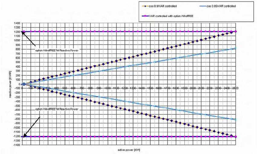
(1) The project is required to have the capability to inject or withdraw reactive power continuously
(i.e. dynamically) at the connection point up to 33% of its rated active power at all levels of active
power output.
Based on the equivalent collector impedance parameters provided by the connection applicant, a
static capacitive compensation device of at least 7 Mvar@34.5 kV installed at the project collector
bus would satisfy the reactive power requirement. The required capacitive compensation shall be
implemented as a part of wind farm control system that automatically controls the switching of
capacitor banks to regulate the overall WTGs’ reactive output to around zero output.
The connection applicant has the obligation to ensure that the wind farm has the capability to
meet the Market Rules requirement at the connection point and be able to confirm this capability
during the commissioning tests.
The connection applicant is required to provide a finalized copy of the functional description of
the wind farm control systems for approval to the IESO before the project is allowed to connect.
(2) Special protection system facilities must be installed at the project to accept a single pair (A & B)
of G/R signals from the BSPS, and disconnect the project from the system with no intentional
time delay when armed for G/R following a triggering contingency. These special protection
system facilities must also comply with the NPCC Reliability Reference Directory #7 for Type 1
special protection systems. In particular, if the SPS is designed to have ‘A’ and ‘B’ protection at a
single location for redundancy, they must be on different non-adjacent vertical mounting
assemblies or enclosures. Two independent trip coils are required on the breakers selected for
G/R. The applicant must provide two dedicated communication channels, separated physically
and geographically diverse, between the project and the Bruce NGS.
To disconnect the project from the system for G/R, simultaneous tripping of the two 230 kV
breakers at the connection point shall be initiated with no accompanying breaker failure response.
After being tripped by the BSPS, the closing of the breakers is not permitted until approval is
obtained from the IESO. Alternative solutions to disconnect the project from the system for G/R
may be acceptable upon the approval of the IESO.
2 CAA ID 2011-447 Final Report – December 21, 2011System Impact Assessment Report Executive Summary
General Requirements: The connection applicant shall satisfy all applicable requirements and
standards specified in the Market Rules and the Transmission System Code. The following
requirements summarize some of the general requirements that are applicable to the project, and
presented in detail in section 2 of this report.
(1) The connection applicant shall ensure that the project has the capability to operate continuously
between 59.4Hz and 60.6Hz and for a limited period of time in the region above straight lines
on a log-linear scale defined by the points (0.0s, 57.0Hz), (3.3s, 57.0Hz), and (300s, 59.0Hz).
The project shall respond to frequency increase by reducing the active power with an average
droop based on maximum active power adjustable between 3% and 7% and set at 4%.
Regulation deadband shall not be wider than ± 0.06%. The project shall respond to system
frequency decline by temporarily boosting its active power output for some time (i.e. 10 s) by
recovering energy from the rotating blades, if this technology is available.
(2) The connection applicant shall ensure that the project has the capability to supply continuously
all levels of active power output for 5% deviations in terminal voltage.
The project shall inject or withdraw reactive power continuously (i.e. dynamically) at a
connection point up to 33% of its rated active power at all levels of active power output except
where a lesser continually available capability is permitted by the IESO.
The project shall have the capability to regulate automatically voltage within ±0.5% of any set
point within ±5% of rated voltage at a point whose impedance (based on rated apparent power
and rated voltage) is not more than 13% from the highest voltage terminal. If the AVR target
voltage is a function of reactive output, the slope ∆V/∆Qmax shall be adjustable to 0.5%. The
response of the project for voltage changes shall be similar or better than that of a generation
facility with a synchronous generation unit and an excitation system that meets the
requirements of Appendix 4.2.
(3) The project shall have the capability to ride through routine switching events and design criteria
contingencies assuming standard fault detection, auxiliary relaying, communication, and rated
breaker interrupting times unless disconnected by configuration.
(4) The connection applicant shall ensure that the 230 kV equipment is capable of continuously
operating between 220 kV and 250 kV. Protective relaying must be set to ensure that
transmission equipment remains in-service for voltages between 94% of the minimum
continuous value and 105% of the maximum continuous value specified in Appendix 4.1 of the
Market Rules.
(5) The connection applicant shall ensure that the connection equipment is designed to be fully
operational in all reasonably foreseeable ambient temperature conditions. The connection
equipment must also be designed so that the adverse effects of its failure on the
IESO-controlled grid are mitigated. This includes ensuring that all circuit breakers fail in the
open position.
(6) The connection applicant shall install at the project a disturbance recording device with clock
synchronization that meets the technical specifications provided by the transmitter.
(7) The connection applicant shall ensure that the new equipment at the project be designed to
sustain the fault levels in the area. If any future system changes result in an increased fault level
higher than the equipment’s capability, the connection applicant is required to replace the
equipment with higher rated equipment capable of sustaining the increased fault level, up to
maximum fault level specified in Appendix 2 of the Transmission System Code.
Fault interrupting devices must be able to interrupt fault currents at the maximum continuous
voltage of 250 kV.
Final Report – December 21, 2011 CAA ID 2011-447 3Executive Summary IESO_REP_0761
(8) Appendix 2 of the Transmission System Code states that the maximum rated interrupting time
for the 230 kV breakers must be 3 cycles or less. Thus, the connection applicant shall ensure
that the installed breakers meet the required interrupting time specified in the Transmission
System Code.
(9) The connection applicant shall ensure that the new protection systems at the project are
designed to satisfy all the requirements of the Transmission System Code and any additional
requirements identified by the transmitter.
As currently assessed by the IESO, the project is not part of the Bulk Power System (BPS) and,
therefore it is not designated as essential to the power system.
The protection systems within the project must only trip the appropriate equipment required to
isolate the fault.
The autoreclosure of the high voltage breakers at the connection point must be blocked. Upon
its opening for a contingency, the high voltage breaker must be closed only after the IESO
approval is granted.
Any modifications made to protection relays after this SIA is finalized must be submitted to the
IESO as soon as possible or at least six (6) months before any modifications are to be
implemented on the existing protection systems.
(10) The connection applicant shall ensure that the telemetry requirements are satisfied as per the
applicable Market Rules requirements. The determination of telemetry quantities and telemetry
testing will be conducted during the IESO Facility Registration/Market Entry process.
(11) If revenue metering equipment is being installed as part of this project, the connection applicant
should be aware that revenue metering installations must comply with Chapter 6 of the IESO
Market Rules. For more details the connection applicant is encouraged to seek advice from
their Metering Service Provider (MSP) or from the IESO metering group.
(12) The project must be compliant with applicable reliability standards set by the North American
Electric Reliability Corporation (NERC) and the North East Power Coordinating Council
(NPCC) that are in effect in Ontario as mapped in the following link:
http://www.ieso.ca/imoweb/ircp/orcp.asp.
(13) The connection applicant will be required to be a restoration participant. Details regarding
restoration participant requirements will be finalized at the Facility Registration/Market Entry
Stage.
(14) The connection applicant must complete the IESO Facility Registration/Market Entry process
in a timely manner before IESO final approval for connection is granted.
Models and data, including any controls that would be operational, must be provided to the
IESO at least seven months before energization to the IESO-controlled grid. This includes both
PSS/E and DSA software compatible mathematical models. The models and data may be
shared with other reliability entities in North America as needed to fulfill the IESO’s
obligations under the Marker Rules, NPCC and NERC rules.
The connection applicant must also provide evidence to the IESO confirming that the
equipment installed meets the Market Rules requirements and matches or exceeds the
performance predicted in this assessment. This evidence shall be either type tests done in a
controlled environment or commissioning tests done on-site. The evidence must be supplied to
the IESO within 30 days after completion of commissioning tests. If the submitted models and
data differ materially from the ones used in this assessment, then further analysis of the project
will need to be done by the IESO.
4 CAA ID 2011-447 Final Report – December 21, 2011System Impact Assessment Report Executive Summary
(15) The Market Rules governing the connection of renewable generation facilities in Ontario are
currently being reviewed through the SE-91 stakeholder initiative and, therefore, new
connection requirements (in addition to those outlined in the SIA), may be imposed in the
future. The connection applicant is encouraged to follow developments and updates through the
following link: http://www.ieso.ca/imoweb/consult/consult_se91.asp.
Notification of Conditional Approval
The proposed connection of the Grand Bend Wind Farm, operating up to 100MW, subject to the
requirements specified in this report, is expected to have no material adverse impact on the reliability
of the integrated power system.
It is recommended that a Notification of Conditional Approval for Connection be issued for the Grand
Bend Wind Farm subject to the implementation of the requirements outlined in this report.
– End of Section –
Final Report – December 21, 2011 CAA ID 2011-447 5Project Description IESO_REP_0761
1. Project Description
Grand Bend L.P. has proposed to develop a 100 MW wind farm located in Zurich, Ontario, known as
Grand Bend Wind Farm which has been awarded a Power Purchase Agreement under the FIT
program with the Ontario Power Authority. It is expected that commercial operation will start
October 2013.
The wind farm will be connected to Hydro One’s 230 kV circuit B23D, 2.77 km south of Seaforth TS
via a 30 km 230 kV overhead tap line. The project will consist of 40 units of GE 2.5MW wind
turbines. These wind turbines will be arranged into 3 groups of 13 or 14 turbines each. The collector
feeder for each group of turbines will be connected to a 34.5 kV bus via a circuit breaker, which in
turn will be connected to a 34.5/230 kV step-up transformer through a disconnect switch. A 230 kV
circuit breaker and a 230 kV motorized disconnect switch will be installed between the high-voltage
side of the step-up transformer and the 230 kV tap line. At the other end of the tap line, two
additional 230 kV circuit breakers and a 230 kV motorized disconnect switch will connect the tap line
to circuit B23D.
The proposed connection arrangement is shown in Figure 1, Appendix A.
– End of Section –
6 CAA ID 2011-447 Final Report – December 21, 2011System Impact Assessment Report General Requirements
2. General Requirements
The connection applicant shall satisfy all applicable requirements and standards specified in the
Market Rules and the Transmission System Code. The following sections highlight some of the
general requirements that are applicable to the project.
2.1 Frequency/Speed Control
As per Appendix 4.2 of the Market Rules, the connection applicant shall ensure that the project has
the capability to operate continuously between 59.4 Hz and 60.6 Hz and for a limited period of time
in the region above straight lines on a log-linear scale defined by the points (0.0 s, 57.0 Hz), (3.3 s,
57.0 Hz), and (300 s, 59.0 Hz), as shown in the following figure.
The project shall respond to frequency increase by reducing the active power with an average droop
based on maximum active power adjustable between 3% and 7% and set at 4%. Regulation deadband
shall not be wider than ± 0.06%. The project shall respond to system frequency decline by
temporarily boosting its active power output for some time (i.e. 10 s) by recovering energy from the
rotating blades. This usually refers to “inertia emulation control” function within the wind farm
control system. It is not required for wind facilities to provide a sustained response to system
frequency decline. The connection applicant will need to indicate to the IESO whether the function of
inertia emulation control is commercially available for the proposed type of wind turbine generator at
the time when the wind farm comes into service. If this function is available, the connection applicant
is required to implement it before the project can be placed in-service. If this function is commercially
unavailable, the IESO reserves the right to ask the connection applicant to install this function in the
future, once it is commercially available for the proposed type of wind turbine generator.
2.2 Reactive Power/Voltage Regulation
The project is directly connected to the IESO-controlled grid, and thus, the connection applicant shall
ensure that the project has the capability to:
- supply continuously all levels of active power output for 5% deviations in terminal voltage.
Rated active power is the smaller output at either rated ambient conditions (e.g. temperature,
Final Report – December 21, 2011 CAA ID 2011-447 7General Requirements IESO_REP_0761
head, wind speed, solar radiation) or 90% of rated apparent power. To satisfy steady-state
reactive power requirements, active power reductions to rated active power are permitted;
- inject or withdraw reactive power continuously (i.e. dynamically) at a connection point up to
33% of its rated active power at all levels of active power output except where a lesser
continually available capability is permitted by the IESO. If necessary, shunt capacitors must
be installed to offset the reactive power losses within the project in excess of the maximum
allowable losses. If generators do not have dynamic reactive power capabilities, dynamic
reactive compensation devices must be installed to make up the deficient reactive power;
- regulate automatically voltage within ±0.5% of any set point within ±5% of rated voltage at a
point whose impedance (based on rated apparent power and rated voltage) is not more than
13% from the highest voltage terminal. If the AVR target voltage is a function of reactive
output, the slope ∆V/∆Qmax shall be adjustable to 0.5%. The response of the project for
voltage changes shall be similar to or better than the response of a generation facility with a
synchronous generation unit and an excitation system that meets the requirements of Appendix
4.2.
2.3 Voltage Ride Though Capability
The project shall have the capability to ride through routine switching events and design criteria
contingencies assuming standard fault detection, auxiliary relaying, communication, and rated breaker
interrupting times unless disconnected by configuration.
2.4 Voltage
Appendix 4.1 of the Market Rules states that under normal operating conditions, the voltages in the
230 kV system are maintained within the range of 220 kV to 250 kV. Thus, the IESO requires that the
230 kV equipment in Ontario must have a maximum continuous voltage rating of at least 250 kV.
Protective relaying must be set to ensure that transmission equipment remains in-service for voltages
between 94% of the minimum continuous value and 105% of the maximum continuous value
specified in Appendix 4.1of the Market Rules.
2.5 Connection Equipment Design
The connection applicant shall ensure that the connection equipment is designed to be fully
operational in all reasonably foreseeable ambient temperature conditions. The connection equipment
must also be designed so that the adverse effects of its failure on the IESO-controlled grid are
mitigated. This includes ensuring that all circuit breakers fail in the open position.
2.6 Disturbance Recording
The connection applicant is required to install at the project a disturbance recording device with clock
synchronization that meets the technical specifications provided by the transmitter. The device will be
used to monitor and record the response of the project to disturbances on the 230 kV system in order
to verify the dynamic response of generators. The quantities to be recorded, the sampling rate and the
trigger settings will be provided by the transmitter.
8 CAA ID 2011-447 Final Report – December 21, 2011System Impact Assessment Report General Requirements 2.7 Fault Level The Transmission System Code requires the new equipment to be designed to sustain the fault levels in the area where the equipment is installed. Thus, the connection applicant shall ensure that the new equipment at the project is designed to sustain the fault levels in the area. If any future system changes result in an increased fault level higher than the equipment’s capability, the connection applicant is required to replace the equipment with higher rated equipment capable of sustaining the increased fault level, up to maximum fault level specified in the Transmission System Code. Appendix 2 of the Transmission System Code establishes the maximum fault levels for the transmission system. For the 230 kV system, the maximum 3 phase symmetrical fault level is 63 kA and the maximum single line to ground symmetrical fault level is 80 kA (usually limited to 63 kA). Fault interrupting devices must be able to interrupt fault currents at the maximum continuous voltage of 250 kV. 2.8 Breaker Interrupting Time Appendix 2 of the Transmission System Code states that the maximum rated interrupting time for the 230 kV breakers must be 3 cycles or less. Thus, the connection applicant shall ensure that the installed breakers meet the required interrupting time specified in the Transmission System Code. 2.9 Protection System The connection applicant shall ensure that the protection systems are designed to satisfy all the requirements of the Transmission System Code as specified in Schedules E, F and G of Appendix 1 and any additional requirements identified by the transmitter. New protection systems must be coordinated with the existing protection systems. Facilities that are essential to the power system must be protected by two redundant protection systems according to section 8.2.1a of the TSC. These redundant protections systems must satisfy all requirements of the TSC, and in particular, they must not use common components, common battery banks or common secondary CT or PT windings. As currently assessed by the IESO, this project is not on the current Bulk Power System list, and therefore, is not considered essential to the power system. In the future, as the electrical system evolves, this project may be placed on the BPS list. The protection systems within the project must only trip the appropriate equipment required to isolate the fault. After the project begins commercial operation, if an improper trip of the 230 kV circuit B23D occurs due to events within the project, the project may be required to be disconnected from the IESO-controlled grid until the problem is resolved. The autoreclosure of the high voltage breakers at the connection point must be blocked. Upon its opening for a contingency, the high voltage breaker must be closed only after the IESO approval is granted. Any modifications made to protection relays after this SIA is finalized must be submitted to the IESO as soon as possible or at least six (6) months before any modifications are to be implemented on the existing protection systems. If those modifications result in adverse impacts, the connection applicant and the transmitter must develop mitigation solutions. Final Report – December 21, 2011 CAA ID 2011-447 9
General Requirements                                                                   IESO_REP_0761

2.10         Telemetry
If applicable according to Section 7.3 of Chapter 4 of the Market Rules, the connection applicant shall
provide to the IESO the applicable telemetry data listed in Appendix 4.15 of the Market Rules on a
continual basis. The data shall be provided in accordance with the performance standards set forth in
Appendix 4.19, subject to Section 7.6A of Chapter 4 of the Market Rules. The data is to consist of
certain equipment status and operating quantities which will be identified during the IESO Facility
Registration/Market Entry Process.
To provide the required data, the connection applicant must install at this project monitoring
equipment that meets the requirements set forth in Appendix 2.2 of Chapter 2 of the Market rules. As
part of the IESO Facility Registration/Market Entry process, the connection applicant must also
complete end to end testing of all necessary telemetry points with the IESO to ensure that standards
are met and that sign conventions are understood. All found anomalies must be corrected before
IESO final approval to connect any phase of the project is granted.

2.11         Revenue Metering
If revenue metering equipment is being installed as part of this project, the connection applicant
should be aware that revenue metering installations must comply with Chapter 6 of the IESO Market
Rules. For more details the connection applicant is encouraged to seek advice from their Metering
Service Provider (MSP) or from the IESO metering group.

2.12         Reliability Standards
Prior to connecting to the IESO controlled grid, the project must be compliant with the applicable
reliability standards established by the North American Electric Reliability Corporation (NERC) and
reliability criteria established by the Northeast Power Coordinating Council (NPCC) that are in effect
in Ontario. A mapping of applicable standards, based on the proponent’s/connection applicant’s
market role/OEB license can be found here: http://www.ieso.ca/imoweb/ircp/orcp.asp
This mapping is updated periodically after new or revised standards become effective in Ontario.
The current versions of these NERC standards and NPCC criteria can be found at the following
websites:
http://www.nerc.com/page.php?cid=2|20
http://www.npcc.org/documents/regStandards/Directories.aspx
The IESO monitors and assesses market participant compliance with a selection of applicable
reliability standards each year as part of the Ontario Reliability Compliance Program. To find out
more about this program, write to orcp@ieso.ca or visit the following webpage:
http://www.ieso.ca/imoweb/ircp/orcp.asp

Also, to obtain a better understanding of the applicable reliability compliance obligations and engage
in the standards development process, we recommend that the proponent/ connection applicant join
the IESO’s Reliability Standards Standing Committee (RSSC) or at least subscribe to their mailing
list by contacting rssc@ieso.ca. The RSSC webpage is located at:
http://www.ieso.ca/imoweb/consult/consult_rssc.asp.

10                                            CAA ID 2011-447                  Final Report – December 21, 2011
System Impact Assessment Report                                                    General Requirements

2.13         Restoration Participant
According to the Market Manual 7.8 which states restoration participant criteria and obligations, the
connection applicant will be required to be a restoration participant. Details regarding restoration
participant requirements will be finalized at the Facility Registration/Market Entry Stage.

2.14         Facility Registration/Market Entry
The connection applicant must complete the IESO Facility Registration/Market Entry process in a
timely manner before IESO final approval for connection is granted.
Models and data, including any controls that would be operational, must be provided to the IESO.
This includes both PSS/E and DSA software compatible mathematical models representing the new
equipment for further IESO, NPCC and NERC analytical studies. The models and data may be shared
with other reliability entities in North America as needed to fulfill the IESO’s obligations under the
Marker Rules, NPCC and NERC rules. The connection applicant may need to contact the software
manufacturers directly, in order to have the models included in their packages. This information
should be submitted at least seven months before energization to the IESO-controlled grid, to allow
the IESO to incorporate this project into IESO work systems and to perform any additional reliability
studies.
As part of the IESO Facility Registration/Market Entry process, the connection applicant must
provide evidence to the IESO confirming that the equipment installed meets the Market Rules
requirements and matches or exceeds the performance predicted in this assessment. This evidence
shall be either type tests done in a controlled environment or commissioning tests done on-site. In
either case, the testing must be done not only in accordance with widely recognized standards, but
also to the satisfaction of the IESO. Until this evidence is provided and found acceptable to the
IESO, the Facility Registration/Market Entry process will not be considered complete and the
connection applicant must accept any restrictions the IESO may impose upon this project’s
participation in the IESO-administered markets or connection to the IESO-controlled grid. The
evidence must be supplied to the IESO within 30 days after completion of commissioning tests.
Failure to provide evidence may result in disconnection from the IESO-controlled grid.
If the submitted models and data differ materially from the ones used in this assessment, then further
analysis of the project will need to be done by the IESO.

2.15         Other Connection Requirements
The Market Rules governing the connection of renewable generation facilities in Ontario are
currently being reviewed through the SE-91 stakeholder initiative and, therefore, new connection
requirements (in addition to those outlined in the SIA), may be imposed in the future. The connection
applicant is encouraged to follow developments and updates through the following link:
http://www.ieso.ca/imoweb/consult/consult_se91.asp

                                           -End of Section-

Final Report – December 21, 2011         CAA ID 2011-447                                                 11
Data Verification IESO_REP_0761
3. Data Verification
3.1 Connection Arrangement
As identified in the Protection Impact Assessment completed by Hydro One (Section 5 and Appendix
B of this report), a second 230 kV breaker in series with the proposed breaker will be installed at the
connection point.
The connection arrangement of the project will not reduce the level of reliability of the integrated
power system and is, therefore, acceptable to the IESO.
3.2 GE 2.5 MW - 103 WTG
The GE 2.5MW - 103 WTG is a three bladed, variable pitch, variable speed, and full conversion wind
turbine generator system. Its specifications are shown in Table 1.
Table 1: Specifications of GE2.5 MW WTG
Rated Rated Rated Transformer Qmax Qmin
Type (MX) (MX)
Voltage MVA MW MVA R X
GE 2.5 - 103 690 V 3 2.5 2.8 0.0 6% 1.21 -1.21
Voltage Ride-Through Capability
The proposed GE 2.5MW wind turbine will be equipped with the Zero Voltage Ride-Through option
(ZVRT). During a voltage drop/raise, the minimum time for a WTG to remain online is shown in
Table 2.
Table 2: WTG Voltage Ride-Through Capability
Voltage Range (% of base voltage) Minimum time for WTGs to Remain Online (sec)
VSystem Impact Assessment Report Data Verification
Frequency Ride-Through Capability
The GE 2.5MW wind turbine can remain online continuously for abnormal frequency ±2.5 Hz, and
stay online for 10 seconds for abnormal frequency ±5 Hz.
The Market Rules state that the generation facility directly connecting to the IESO-controlled grid
shall operate continuously between 59.4Hz and 60.6Hz and for a limited period of time in the region
above straight lines on a log-linear scale defined by the points (0.0s, 57.0Hz), (3.3s, 57.0Hz), and
(300s, 59.0Hz).
The frequency ride-through capability of the proposed WTGs meets the Market Rules’ requirements.
3.3 Main Step-Up Transformers
Table 3: Main Step-Up Transformer Data
Positive Sequence Configuration Zero Sequence
Rating (MVA)
Unit Voltage Impedance (pu) Impedance (pu) Tap
(ONAN/ONAF/ONAF) HV LV
SB= 75 MVA SB= 75 MVA
ULTC@ HV:
T1 230/34.5 kV 75/100/125MVA 0.00+j0.10 Yg Delta 0.00+j0.047 17 steps, 226-
251.5 kV
3.4 Collector System
Table 4: Equivalent Impedance of Collectors
Positive-Sequence Impedance Zero-Sequence Impedance(*)
Circuit Unit# MW (pu, SB=100MVA) (pu, SB=100MVA)
R X B R X B
C1 14 35 0.04781 0.11502 0.00089 N/A N/A N/A
C2 13 32.5 0.04781 0.11502 0.00089 N/A N/A N/A
C3 13 32.5 0.04781 0.11502 0.00089 N/A N/A N/A
(*) Zero-sequence impedance has not been provided. Typical data was assumed during the SIA. The
applicant needs to provide this data during the IESO Market Entry process.
3.5 Connection Equipment
3.5.1 HV Switches
Table 5: Parameters of HV Disconnect Switches
Continuous Current Short Circuit
Identifier Voltage Rating
Rating Symmetrical Rating
89-LH1 250 kV 1200 A 50 kA
89-LH2 250 kV 1200 A 50 kA
The HV switch meets the maximum continuous voltage rating requirement of 250 kV.
Final Report – December 21, 2011 CAA ID 2011-447 13Data Verification IESO_REP_0761
3.5.2 HV Circuit Breakers
Table 6: Parameters of HV Circuit Breakers
Interrupting Continuous Short Circuit
Identifier Voltage Rating
Time Current Rating Symmetrical Rating
52-L1 250 kV 3 cycles (50 ms) 1200 A 50 kA
52-TL1 250 kV 3 cycles (50 ms) 1200 A 50 kA
The HV circuit breaker meets the maximum continuous voltage rating requirement of 250 kV and the
required 3 cycles or less interrupting time.
The symmetrical rated short circuit breaking current of the 230 kV breakers are 50 kA. This value is
below the maximum 3 phase symmetrical fault level of 63 kA established by the Transmission
System Code for the 230 kV system. Fault studies shown in Section 4 of this report show that the
230kV breaker ratings of 50 kA are sufficient to withstand fault levels at the project. The connection
applicant should be aware that if any future system changes result in increased fault current higher
than the equipment’s capability, the connection applicant would be required to replace these breakers
at its own expense with higher rated breakers up to the maximum fault level of 63 kA.
3.5.3 Tap Line
Table 7: Parameters of the Tap Line
Positive-Sequence Impedance Zero-Sequence Impedance(*)
Length
(pu, SB=100MVA) (pu, SB=100MVA)
(km)
R X B R X B
30 0.00501 0.03132 0.0475 N/A N/A N/A
(*) Zero-sequence impedance has not been provided. Typical data was assumed during the SIA. The
applicant needs to provide this data during the IESO Market Entry process.
3.6 Wind Farm Control System
The proposed wind farm will be equipped with the GE WindCONTROL System. This control system
is designed to interface with each WTG in the wind farm for regulating system voltage, system power
factor and real and actual power for the entire wind farm. It also has the capability to coordinate and
control fixed reactor and capacitor banks when the total reactive requirements for the farm cannot be
supplied by the reactive capability of the WTGs.
Voltage Control
The WindCONTROL System has the following functions related to the voltage control:
• Voltage, VAR and Power Factor Control
The WindCONTROL System has a voltage or power factor closed loop regulator controlling voltage
at the connection point or reactive power injected by the wind farm at the connection point by
regulating the reactive output of the WTGs.
• Fixed Reactor and Cap Bank Control and Coordination
14 CAA ID 2011-447 Final Report – December 21, 2011System Impact Assessment Report Data Verification
The WindCONTROL System is able to control and coordinate the insertion of up to 4 fixed capacitor
or reactor banks. These banks may be operated automatically in conjunction with the voltage or
power factor regulator.
• Line Drop Compensation / Voltage Droop Compensation
The voltage regulator and the power factor regulator can implement line drop-compensating logic to
correct for voltage drops and VAR losses on the line. The voltage regulator can be configured with
voltage droop compensation, which allows tightly coupled adjacent voltage regulators to share in the
voltage regulation of a point that is common to all the adjacent regulators.
The voltage control functions enable the proposed wind farm to operate in voltage control mode and
control voltage at a point whose impedance (based on rated apparent power and voltage of the
project) is not more than 13% from the connection point. Thus, it is acceptable to the IESO.
The function of voltage control meets the requirements of the Market Rules.
Frequency Control
The WindCONTROL System has a function of frequency droop control which controls the wind farm
power output based upon the grid frequency. This function is similar to governor droop control for a
conventional rotating generator.
The WindCONTROL System also has the feature of WindINERTIA which enables the GE 2.5 MW
WTG to provide inertial response to help stabilize grid frequency. This feature supports the grid
during under frequency events by providing a temporary increase in power production for a short
duration, contributing towards frequency recovery. This is achieved by tapping into the stored kinetic
energy in the rotor mass.
The function of frequency control meets the requirements of the Market Rules.
-End of Section-
Final Report – December 21, 2011 CAA ID 2011-447 15Short Circuit Assessment IESO_REP_0761
4. Short Circuit Assessment
Fault level studies were completed by the transmitter to examine the effects of the project on fault
levels at existing facilities in the surrounding area. Studies were performed to analyze the fault levels
with and without the project and other recently committed generation projects in the system.
The short circuit study was carried out with the following primary system assumptions:
(1) Generation Facilities In-Service
East
Lennox G1-G4 Chenaux G1-G8
Kingston Cogen G1-G2 Mountain Chute G1-G2
Wolf Island 300 MW Stewartville G1-G5
Arnprior G1-G2 Brockville G1
Barrett Chute G1-G4 Havelock G1
Chats Falls G2-G9 Saunders G1-G16
Cardinal Power G1, G2
Toronto
Pickering units G1, G4-G8 Sithe Goreway G11-13, G15
Darlington G1-G4 TransAlta Douglas G1-G3
Portlands GS G1-G3 GTAA G1-G3
Algonquin Power G1, G2 Brock west G1
Whitby Cogen G1
Niagara
Thorold GS GTG1, STG2 Beck 2 G11-G26
Beck 1 G3-G10 Beck 2 PGS G1-G6
Decew G1, G2, ND1
South West
Nanticoke G1, G2, G5-G8 Kingsbridge WGS 39.6 MW
Halton Hills GS G1-G3 Amaranth WGS 199.5 MW
Bruce
Bruce A G1-G4 Ripley WGS 76 MW
Bruce B G5-G8 Underwood WGS 198 MW
Bruce A Standby SG1
West
Lambton units G3-G4 Imperial Oil G1
Brighton Beach G1, G1A, G1B Kruger Port Alma WGS 101.2 MW
Greenfield Energy Centre G1-G4 Gosfield Wind Project 50.6 MW
St. Clair Energy Centre CTG3, STG3, CTG4, STG4 Kruger Energy Chatham WF 101 MW
East Windsor Cogen G1-G2 Raleigh Wind Energy Centre 78 MW
TransAlta Sarnia G861, G871, G881, G891 Talbot Wind Farm 98.9 MW
Ford Windsor CTS STG5 Dow Chemicals G1, G2, G5
TransAlta Windsor G1, G2 Port Burwell WGS 99 MW
West Windsor Power G1, G2 Fort Chicago London Cogen 23 MVA
Great Northern Tri-Gen Cogen 15 MVA
(2) Previously Committed Generation Facilities
• Bruce G1, G2 • Port Dover and Nanticoke
Wind Project
16 CAA ID 2011-447 Final Report – December 21, 2011System Impact Assessment Report Short Circuit Assessment
• Big Eddy GS and Half Mile Rapids GS • Grand Renewable Energy
• White Pines Wind Farm • Park
Greenfield South
• Amherst Island • Comber East C24Z
• York Energy Centre • Comber West C23Z
• Conestogo Wind Energy Centre 1 • Pointe-Aux-Roches Wind
• Dufferin Wind Farm • South Kent Wind Farm
• Summerhaven Wind Farm
(3) Recently Committed Generation Facilities
• Bluewater Wind Energy Centre • East Lake St. Clair Wind
• Jericho Wind Energy Centre • Adelaide Wind Power
• Bornish Wind Energy Centre • Project
Gunn’s Hill Wind Farm
• Goshen Wind Energy Centre • Silvercreek Solar Park
• Cedar Point Wind Power Project Phase II • K2 wind
• Adelaide Wind Energy Centre • Armow
• Grand Bend Wind Farms • 300 MW wind at Orangeville
• Grand Valley Wind Farms (Phase 3) • 100 MW at S2S
• Erieau Wind
(4) Existing and Committed Embedded Generation
• Essa area: 264 MW • Niagara area: 52 MW
• Ottawa area: 90 MW • Southwest area: 348 MW
• East area: 580 MW • Bruce area: 26 MW
• Toronto area: 168 MW • West area: 585 MW
(5) Transmission System Upgrades
• Leaside - Bridgman reinforcement: Leaside TS to Birch JCT: build new 115 kV circuit
(CAA2006-238);
• St. Catherines 115 kV circuit upgrade: circuits D9HS, D10S and Q11S (CAA2007-257);
• Tilbury West DS second connection point for DESN arrangement using K2Z and K6Z
(CAA2008-332);
• Second 500kV Bruce-Milton double-circuit line (CAA2006-250);
• Woodstock Area transmission reinforcement (CAA2006-253);
o Karn TS in service and connected to M31W & M32W at Ingersol TS
o W7W/W12W terminated at LFarge CTS
o Woodstock TS connected to Karn TS
• Rodney (Duart) TS DESN connected to W44LC and W45LS 230 kV circuits (CAA2007-
260)
(6) System Operation Conditions
• Lambton TS 230 kV operated open • Cherrywood TS north & south 230kV
• Claireville TS 230 kV operated open buses operated open
• Leaside TS 230 kV operated open • Richview TS 230 kV bus operated open
• Leaside TS 115 kV operated open • All tie-lines in service and phase shifters on
• Middleport TS 230 kV bus operated open neutral taps
• Hearn SS 115 kV bus operated open • Maximum voltages on the buses
Table 8 summarizes the fault levels at facilities near the project with and without the project
and other recently committed generation projects.
Final Report – December 21, 2011 CAA ID 2011-447 17Short Circuit Assessment IESO_REP_0761
Table 8: Fault Levels at Facilities Near the Project
After the Project & Lowest Rating of
Before the Project
Committed Generation Circuit Breakers
3-Phase L-G 3-Phase L-G (kA)
Symmetrical (kA)*
Bruce A 230 kV 43.0 54.4 44.6 56.2 65***
Detweiler 230 kV 22.9 19.8 23.7 20.3 40
Majestic B23D 230 kV 18.1 16.2 18.6 16.5 63
Grand Bend PCC 230 kV - - 8.3 8.2 50
Grand Bend 230 kV - - 4.7 5.3 50
Seaforth 115 kV 11.6 13.6 13.7 16.3 29.5
Detweiler 115 kV 24.2 27.1 24.7 27.5 39.3
Asymmetrical (kA)*
Bruce A 230 kV 57.6 78.4** 59.7 80.8** 72.6***
Detweiler 230 kV 26.8 25.3 27.8 25.9 42.1
Majestic 230 kV 21.8 18.3 22.2 18.6 66.3
Grand Bend PCC 230 kV - - 9.9 10.1 (unknown)****
Grand Bend 230 kV - - 5.5 6.5 (unknown)****
Seaforth 115 kV 12.9 16.0 15.6 19.6 34.1
Detweiler 115 kV 28.1 33.3 28.7 33.9 45.4
* Based on a pre-fault voltage level of 550 kV for 500 kV buses, 250 kV for 230 kV buses, and 127 kV for 115
kV buses.
**The asymmetrical fault level is based on a breaker contact parting time of 44 ms.
***Three lower rated Bruce A 230 kV breakers (D1L81, K1L82 and L23T25) are scheduled to be replaced by
December 2012 (see CAA ID#2010-EX511). The listed lowest rated circuit breaker value for Bruce A 230 kV
assumes these breakers being replaced.
****The applicant must provide the asymmetrical rating of the 230 kV circuit breakers during the IESO Market
Entry process.
Table 8 shows the interrupting capability of the 230 kV circuit breakers of the project is adequate for
the anticipated fault levels.
The results also show that the line-to-ground asymmetrical fault current at Bruce A 230 kV before
and after the incorporation of the project and other committed projects will exceed the interrupting
capability of the existing breakers. This issue has been investigated in the 2nd SIA addendum for the
project of Bruce G1 and G2 restart (CAA ID 2004-163), where the IESO has identified a requirement
to replace all the Bruce 230 kV breakers with higher fault current interrupting capability and assessed
potential mitigation measures for this issue until these circuit breakers are replaced. Hydro One has
planned to replace the Bruce 230 kV breakers.
With the exception of Bruce A 230 kV, the interrupting capability of the lowest rated circuit breakers
near the project will not be exceeded after the incorporation of the project.
-End of Section-
18 CAA ID 2011-447 Final Report – December 21, 2011You can also read