LVX Global - Smart City Solutions - Jörg Schneck GM Business Development - LonMark International
←
→
Page content transcription
If your browser does not render page correctly, please read the page content below

LVX Global – Smart City Solutions

             Jörg Schneck
               Dipl.-Ing. (FH)

         GM Business Development
          j.schneck@lvxglobal.com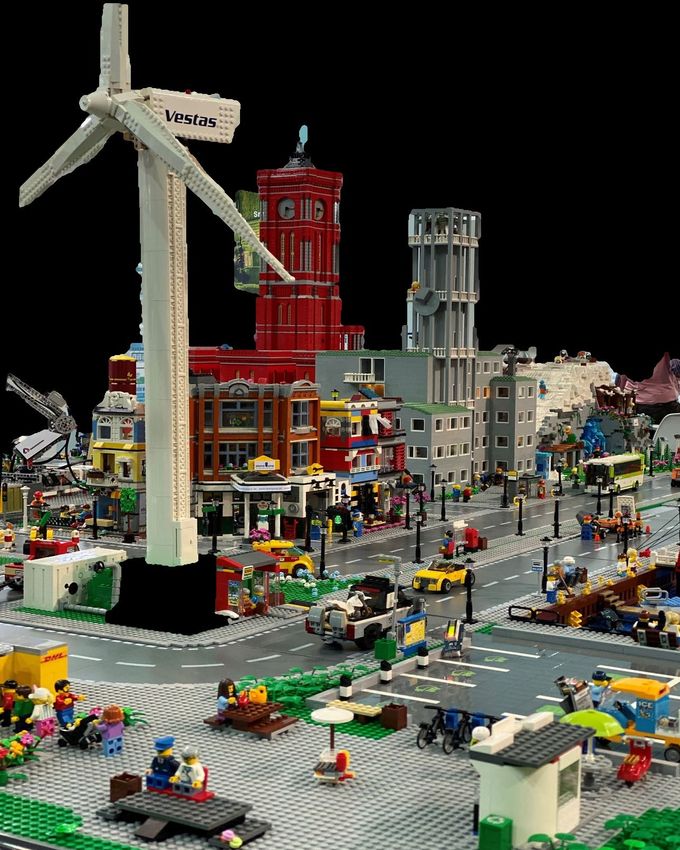
LVX Global – Technology Solutions for Smart Cities and Smart Buildings                                                                2

                                Smart City
                                Smart Building
                                Technology

  LVX Global
  LVX Global is an international technology solutions business that identifies, designs, delivers and manages high value,
  scalable, replicable social outcomes at the intersection of technology, engineering, and human behavioral science.
  With over 30 years’ experience and with operations across Australia and subsidiaries in Europe, Asia, and North
  America, LVX Global is today conceiving, designing, delivering, and managing innovative projects for both government
  and the private sector.
  Smart City and building customers across the world call LVX Global for its engineering and advisory services and with
  access to owned and licensed technology LVX Global is uniquely placed to provide end-to-end solutions.
  LVX Global is passionate about creating a safer, more beautiful, and engaging environment.
  Headquartered in Adelaide, South Australia LVX Global will move to the innovation and technology hub of Lot Fourteen
  from July 2021.

          LVX Global (Deutschland) GmbH · www.icititech.com                                                     Innopolis – September 2021
LVX Global – Works with Customers as an End-to-End Partner                                                                                3

LVX understand’s the complex challenges and opportunities facing organisations today, and has the skills, capability, and experience
to deliver solutions to these.
We have extensive experience in delivering ‘end-to-end’ engineered technology solutions through our “EPCM+F” Engineer; Procure;
Construct; Manage and Fund model. Our team has become a global advisor of choice to product and technology developers and end
users, alike, and a specialist consultant to major global advisory firms, government and industry groups.
We start with clients by developing a strategy through asking what are their most significant issues, and biggest opportunities and we
help design the plan to implement impactful solutions to increase the efficiency, capability, and pleasure of its users. Our planning
process includes working with you on feasibility, funding, design, delivery, communication, and ongoing review.
We bring together a wide range of skill-sets and experience under a forward thinking and agile banner. Our team consists of leaders in
their fields and have an expansive network of partners.

For Smart Cities the Smart Lighting is the starting point!
• Street lighting opens up new ways for modern urban planning
• The above-mentioned topics are implemented with built-in sensors
    • by collecting environmental data, creating urban safety, experiential spaces through light management or
      wireless internet access.

           LVX Global (Deutschland) GmbH · www.icititech.com                                                        Innopolis – September 2021
LVX Global – Worldwide Competence - The Team                                                                                                  4

MANAGEMENT TEAM

                                                                                 Mark Verheyen
        Corey Gray                                   Geoff Weir                  Director, President        Greg Stirling
        Director, Founder, CEO                       Chief Financial Officer     North America              Chief Growth Officer

                                                      Kane Pryzibilla
        Sanjeewa Jayakody                             General Manager            Dean Jones                 SH Cho
        Chief Technology Officer                      – Technology               General Manager IoT        Managing Director Asia

SALES TEAM EU

        Grainne Flynn
        Managing Director                             Jörg Schneck               André Karl                 Christina Hoffmann
        LVX Europe                                    GM Business Development    Head of Sales D – A – CH   GM Mktg / Admin

R&D TEAM EU

        Matthias Lürkens
        GM Connectivity                               Horst Kremer-Merseburg,    Juraj Matus                Stefan Gutowsky
        & Standardization                             GM Application Solutions   GM Innovation              Lead Software Developer

         LVX Global (Deutschland) GmbH · www.icititech.com                                                              Innopolis – September 2021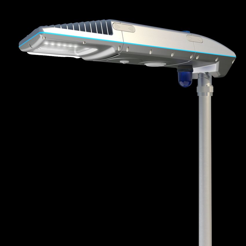
LVX Global – Strong Brands under One Roof                                                                                                                                                                                           5

                                                                                                Headquarter LVX Global
                                                                                                  Adelaide, Australia

                          Adelaide, Australia                                                       Adelaide, Australia                                                        Frankfurt, Germany
      FireM is an IoT Technology enabled engineer-led end-to-end            Norman Asset Delivery consults to clients in the resources, property and    iciti enables your smart city and building opportunities to be realised.
     solution that identifies and maps the location of events within a         public infrastructure sectors offering services such as, engineering,     With tailored solutions and using open protocol technology iciti uses
          building and interfaces to any fire, security or building         project management, design management and authority approvals. With           existing infrastructure to deliver smart communication and control
                            management system.                                extensive experience and outstanding industry relationships Norman          solutions. Significant cost reduction is achieved in installation and
                                                                             Asset Delivery ensures clients successful delivery of assets including    further savings are experienced through life with reduced maintenance
      All fire panel ‘events’ are stored in a common platform on a web                                            :                                          and energy costs. Your risk is minimised with fewer gateways
       application server, where there is easy access to information.              • Buildings (commercial, retail, industrial and residential)        required, a reduction in the points of failure and a system that is future
     In addition, through FireM’s real-time system-status dashboards,                  • Major housing estates (marinas and golf resorts)                                                 proof.
     facility managers can use modern IoT technology to monitor their          • Water and wastewater infrastructure (private and public roads)
     fire safety assets, reduce risk and better protect their properties.                            • Underground railways                            The outcome is all the benefits of smart city infrastructure delivered to
      Where FireM is installed, building occupants can download the                      • Water supply and gas formation water dams                                             your community.
                FireM app and connect to the FireM interface..
                                                                                                  www.normanassoc.com.au                                                         www.icititech.com
                            www.firem.com.au

              LVX Global (Deutschland) GmbH · www.icititech.com                                                                                                                                          Innopolis – September 2021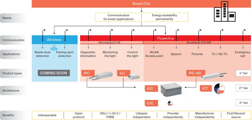
iciti – Street Lighting as a Starting Point for Smart City Applications                                                                                         6

         Use of the
   existing infrastructure
      of street lighting
    for IoT applications

                                               +                               ≥1                                        =
                                                                                                                 Cloud

                            Lighting                         Sensors                    Edge Controllers                         Digital Services

                          Available and            Loudspeakers, sensors and        Central control of all IoT               Simplify customer processes
                           networked                 beacons connectivity                applications                          Generate customer sales
                           everywhere

         LVX Global (Deutschland) GmbH · www.icititech.com                                                                                Innopolis – September 2021
Communication Platform based on Lighting Infrastructure                                                      7

                                                               Camera for security

                                                              Signature information

                                                                  Smart lighting

                                                              Noise indication & map

                                                             E-charging management

                                                                  Smart parking

                                                            Announcement loudspeaker

                                                               Waste management

        LVX Global (Deutschland) GmbH · www.icititech.com                              Innopolis – September 2021
iciti – Functions                                                                                                                                     8

  Motion-controlled, demand-responsive light                               Public information system
  By using motion sensors, light can be controlled according to need.      By means of HD-PLC communication, extensive data, such as
  The movement of people or objects triggers the illuminance over          timetable displays, audio information for the visually impaired or
  several light points. The light runs along with the movement.            advertising can also be played out on corresponding displays.

  Adaptation of the lighting                                               Public safety
  Lighting adapted to the weather conditions by intelligent sensor         Camera systems, loudspeakers and emergency call systems, which
  technology increases safety in road traffic.                             can be easily integrated on luminaire poles, provide more security in
                                                                           public places and urban spaces.

  Lighting management with a system
                                                                           WiFi hotspots in public spaces
  The individual light points or luminaire groups are controlled via the
                                                                           The provision of WiFi hotspots via broadband communication brings
  central system. Stand-alone operation is also possible.
                                                                           real added value to all residents of the city.

  Acquisition of environmental data                                        Charging stations for electric cars
  Appropriate sensors on the luminaire mast enable precise                 For charging electric cars, appropriate charging stations could be
  measurement of various environmental factors in real time.               installed in the lamppost.

  Waste management                                                         Traffic and parking management
  Waste collection on demand is part of modern waste management            Through the use of intelligent sensors, sustainable traffic
  based on intelligent sensor technology on the luminaire pole.            optimisation can be realised by collecting real-time data. Finding
                                                                           free parking spaces more quickly leads to greater satisfaction
                                                                           among the population.
            LVX Global (Deutschland) GmbH · www.icititech.com                                                                   Innopolis – September 2021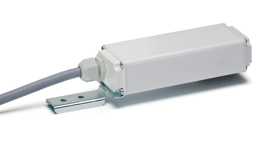
Current Technology Chaos                                                                                                                                9

                          Where no standardisation exists, IP protocol shows how it works

                                                      Control
                                                    Technologies

             Smart City                                                                  Easy to
                                                                                         integrate
                                                                                         W LAN
                                                                                         Camera
                                                                                         Loudspeaker
                                                                    Schneider Intercom
                                                                                         …..
                                                                    City Solingen                      Selux

                                                  IP Technologies

                                                                                                                        Ruckus
                                                                    City Solingen                              City Heringsdorf

        LVX Global (Deutschland) GmbH · www.icititech.com                                                                         Innopolis – September 2021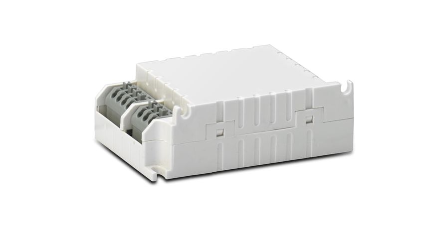
Smart City, what does it actually need?                                                                                                            10

                                                                                   Narrowband technology
                                                                                   PLC, 6LowPan, ZigBee, LTE-NB, LON-RF….
                                                                                   Disadvantage: no standardisation at present

                                                             Data capture          1 Byte to 254 Bytes
                                                              and control          per device

              Smart City                                                    DATA

                                                                                   100kB Speech
                                                             Multimedia
                                                                                   3-5MB HDTV

                                                                                   Broadband technology
                                                                                   HD-PLC, WLAN, LTE, 5G
                                                                                   Advantage: the IP protocol is a standard

         LVX Global (Deutschland) GmbH · www.icititech.com                                                                    Innopolis – September 2021
IoT Systems Today – Device Cloud Connection with Proprietary Communication 11
LoRa
Company A LTE
SigFox
IoT-NB
ZigBee
LORA
GSM Company B
LVX Global (Deutschland) GmbH · www.icititech.com Innopolis – September 2021A Better World with IoT, Local Networking, Cloud Connection and Standardisation 12
IP / LTE
BB-PLC Edge-Controller
SM / MM
NB-PLC / BB-PLC
or RF-MESH
or LTE-NB
LVX Global (Deutschland) GmbH · www.icititech.com Innopolis – September 2021LON Protocol – Supports Different Transmission Media 13
but NO Gateway just a “Router out of the Box”
LVX Global (Deutschland) GmbH · www.icititech.com Innopolis – September 2021LVX Technology Platform 14
IoT Server
SCADA-
Server
NI NI NI NI NI
RF- RF-
BB-PLC NB-PLC Cloud
MESH LORA
HD-PLC NB-PLC RF-MESH IP & LTE-NB LoRa or
LoRa with LON
formatted data
LVX Global (Deutschland) GmbH · www.icititech.com Innopolis – September 2021Typical Smart City Infrastructure 15
IP data 100 MBit
DALI / 1-10 V
& Energy
iCIS
Wireless / LoRa
iDC-IoT
Wireless / LoRa
iDC-SS
SOS
Powerline
Powerline NB-PLC
NB-PLC BB-PLC
LVX Global (Deutschland) GmbH · www.icititech.com Innopolis – September 2021Wireless Mesh Network Requirements 16
Load balanced
Cloud
Routable protocol
requirements
Interoperable
Energy management Router/Gateway
Connection reliability
Robust against disturb.
Scalable Controller
RF-Mesh Interoperable
requirements
Self-organised End node
End-to-End reliable
Encrypted
Lossed
Localisation / ranging controller
Latency / reaction time
Huge number of nodes
Economic Routable protocol
requirements
No recurring cost
Investment protection
LVX Global (Deutschland) GmbH · www.icititech.com Innopolis – September 2021Difference Between Existing Technologies 17
coming
LVX RF-Mesh soon ZigBee IoT-NB LoRa / SigFox
Independent tool
YES NO NO NO
for commissioning
Load balanced Yes No No No
Cloud
Routable protocol Yes, because it’s LON No Yes No
requirements
If you Interoperable Yes, EN 14908.xx No No / with LON yes No
compare all Energy management Yes, outside the backbone Yes Only LTE-NB Yes
requirements Connection reliability Yes, acknowledgement Yes Yes No
Yes, as long communication Yes, as long communication Yes, as long communication Yes, as long communication
where you Robust against disturb. is available is available is available is available
Max. 65536 /
can say Scalable Yes, as thousands of nodes
real approx. 100
Yes Depends on no. of devices
RF-Mesh Interoperable Yes, because it’s LON No Only with LON No
YES requirements
Self-organised Yes, it’s a “must be” No Yes No
it should be End-to-End reliable Yes, it’s a “must be” Yes Yes No
clear this is Encrypted Yes, it’s a “must be” Yes Yes Yes
what the Localisation / ranging GPS is included No No No
Linear, depends on router no. No, depends on connected
market is Latency / reaction time (< 1 sec. over 50 hops)
3 to 5 hops
devices
Depends on no. of devices
Yes, processing time grows
looking for! Huge number of nodes 1000…5000 Real approx. 100 Yes
linearly
Economic Routable protocol Yes No Yes No
requirements
No recurring cost Yes Yes No Yes (LoRa) / No (SigFox)
Investment protection Yes, open technology No No No
LVX Global (Deutschland) GmbH · www.icititech.com Innopolis – September 2021iciti – Decision Matrix for Smart Cities 18
LVX Global (Deutschland) GmbH · www.icititech.com Innopolis – September 2021iciti – Functions / Features of iciti Products 19
LVX Global (Deutschland) GmbH · www.icititech.com Innopolis – September 2021iciti – Product Portfolio 20
Luminaire Controller Edge Controller Accessories
Luminaire Controllers Ref. No. Edge Controllers Ref. No. Accessories Ref. No.
iLC-DALI 187205 iDC-ET 188100 iR-FT/HD (Router) 187214
iLC-1-10V 187206 iDC-R4G 188101 iSS-FT (Smart Server) 186991
iPC-1R 187207 iDC-MM 188102 iSS-PL (Smart Server) 186992
iPC-2R 187208 iDC-SM 188103
iLIC (Software) 186253 iSS-IOT Pro (Smart Server) 200023
iPC-HD 187211
iDC-IoT-IP coming 200011
soon
IOX (DI/DO) 200024
iDC-IoT-R4G 200012
IOX (DI/DO + metering) 200025
iDC-IoT-MM 200013
iDC-IoT-SM 200014 iPL-NI 186993
Software for iDC-IOT
Outlook iCIS – intelligent 1-200 LP 200015 iCCU 186345
• iMCU-RF City Information System 1-500 LP 200016
iPC-HD-C2M 186889
intelligent multi-functional luminaire (min. 100 LP) 1-1000 LP 200017
iPC-HD-C7M 186890
1-2000 LP 200018
controller
1-5000 LP 200019
• iCTI-RF
intelligent hand-held operating
device for iMCU-RF
LVX Global (Deutschland) GmbH · www.icititech.com Innopolis – September 2021iLC iNTELLIGENT LUMINAIRE CONTROLLER (BUILT-IN)
iLC iNTELLIGENTER LEUCHTENCONTROLLER (EINBAU)
iLC Developed for use in street lighting and lighting
in the vicinity of buildings, the interoperable iLC
iNTELLIGENT LUMINAIRE controls magnetic and electronic operating devices
fitted with a 1–10 V, PWM or DALI interface via
CONTROLLER (BUILT-IN) standardised powerline communication in the C/B
band according to CENELEC 50065-1 based on
the OLC LonMark® profile.
Standardised data transmission is in accordance
with ANSI/CEA and EN. Operation is possible both
in the light management system and in stand-alone
mode.
Individually programmable and updateable,
it performs all the tasks of a modern light
management system and thus ensures a high
degree of investment protection.
FURTHER ADVANTAGES
3 Luminaires can be switched off when connected to a
switched lighting cable
3 Power consumption 1 to 3 W
3 Adjustable control input to suit various tasks
3 Connection of various sensors such as motion sensors,
key switches and light sensors
3 10 dimming levels with individual dimming sequences in
stand-alone mode
3 Lighting can be switched on earlier and switched off with a
delay with individual dimming sequences
3 Compensation of reduction in luminous flux with freely
definable values for lamp service life as well as start and end
levels
3 Burning in of high-pressure discharge lamps after lamp
replacement
3 5 years warranty
TYPICAL APPLICATIONS
3 Street lighting and lighting in the vicinity of buildings
3 Car parks, bus stops and railway stations
3 Company premises, warehouses
3 Sports facilities
LVX Global (Deutschland) GmbH
Efficient tech Tannenwaldallee 2
for intelligent cities 61348 Bad Homburg, Germany
info@icititech.com
V-1.0 | 07.2021 www.icititech.com | 1iLC iNTELLIGENT LUMINAIRE CONTROLLER (BUILT-IN)
iLC iNTELLIGENTER LEUCHTENCONTROLLER (EINBAU)
iLC Luminaire Controller iLC Leuchtencontroller
Technical Details Technische Daten
Electronic Luminaire Controller 187205 Elektronischer Leuchtencontroller 187205
Type iLC Typ iLC
Input voltage 110–230 V AC (± 10%) Eingangsspannung 110–230 V AC (± 10 %)
Mains frequency 50/60 Hz Netzfrequenz 50/60 Hz
Power consumption 1–3 W Leistungsverbrauch 1-3 W
Via the power supply line (powerline) in acc. Über die Spannungsversorgung (Powerline)
Communication Kommunikation
with CENELEC 50065-1 gemäß CENELEC 50065-1
C Band Primary band 115–135 kHz C-Band Primär-Band 115–135 kHz
B Band Secondary band 95–115 kHz B-Band Sekundär-Band 95–115 kHz
Data transfer (USA) ANSI/CEA 709.1, ANSI/CEA 709.2 Datenübertragung (USA) ANSI/CEA 709.1, ANSI/CEA 709.2
Data transfer (Europe) EN 14908-1, EN 14908-3 Datenübertragung (Europa) EN 14908-1, EN 14908-3
No electrical isolation from input to output (as soon Keine Potenzialtrennung Eingang zu Ausgang
Galvanic isolation as the electronic device is connected to the iLC, the (sobald das elektronische Betriebsgerät an den iLC
Galvanische Trennung
control input ceases to be electrically isolated) angeschlossen wird, verliert der Steuereingang
seine Basisisolation)
Switching current 4 A (at λ = 0.8)
Schaltstrom 4 A (bei λ = 0,8)
Switching cycles 50,000 switching operations per function (at λ = 0.8)
Schaltzyklen 50.000 Schaltungen pro Funktion (bei λ = 0,8)
Programmable Yes
Programmierbar Ja
Configurable parameters Yes
Parametrierbar Ja
High-voltage control input 230 V AC
Hochvoltsteuereingang 230 V AC
Switching output
1 x for connecting one luminaire
luminaire Schaltausgang Leuchte 1 x zum Anschluss einer Leuchten
1 x DALI, 1–10 V or PWM: short-circuit proof, suitable 1 x DALI, 1–10 V oder PWM: kurzschlussfest,
Control output electronic Steuerausgang elektro
for respective ballasts, DALI bus master interface for geeignet für entsprechende Vorschaltgeräte, DALI-
operating device nisches Betriebsgerät
max. 4 ballasts Busmaster-Schnittstelle für max. 4 Vorschaltgeräte
Connection terminals 0.5–1.5 mm2 Anschlussklemmen 0,5–1,5 mm2
Conductor type of the Leiterart der
Single, stranded Eindrähtig, feindrähtig
connection terminals Anschlussklemme
Firmware update / Firmware-Aktualisierung /
Via powerline Über Powerline
parameter configuration Parameter-Konfiguration
Control and monitoring Steuer- und
Switch on and off, power reduction Ein-/Ausschalten, Leistungsreduzierung
parameters Überwachungsparameter
Voltage, current, power factor, output, energy, Spannung, Strom, Leistungsfaktor, Leistung,
Capture of measured data temperature, lighting hours with an accuracy of Messdatenerfassung Energie, Temperatur, Brennstunden mit einer
better than 1% Genauigkeit von besser als 1 %
Interoperable in acc. with the LonMark® OLC Kompatibel mit dem LonMark®-OLC-Profil,
Software interface profile, use of network variables and configuration Softwareschnittstelle Verwendung von Netzwerkvariablen und
parameters, repeatable Konfigurationsparametern, wiederholbar
Operating temperature Betriebstemperaturbereich
–25 to +80 °C –25 bis +80 °C
range tc tc
Storage temperature Lagertemperaturbereich –25 bis +85 °C
–25 to +85 °C
range Mittlere Betriebsdauer
50.000 Std.
Mean time between failure 50,000 h zwischen Ausfällen (MTBF)
Luftfeuchtigkeit 90 % nicht kondensierend
Humidity 90% non-condensing
Stoßspannungsfestigkeit 4 kV / 1,2 / 50; gemäß EN 61547
Surge voltage protection 4 kV / 1.2 / 50; acc. to EN 61547
Schutzart IP20
Degree of protection IP20
Schutzklasse Geeignet für Leuchten der Schutzklasse I und II
Protection class Suitable for luminaires of protection class I and II
Gehäusematerial PC
Casing material PC
Abmessungen (LxBxH) 93 x 58 x 30 mm
Dimensions (LxWxH) 93 x 58 x 30 mm
Gewicht 100 g
Weight 100 g
Ursprungsland Hergestellt in Serbien
Country of origin Made in Serbia
Zolltarifnummer 8543 7090
Custom tariff number 8543 7090
The values contained in this data sheet can change due to technical innovations. Any such changes will be made without separate notification.
Please find further detailed information at www.icititech.com
Die Werte in diesem Datenblatt können sich aufgrund technischer Innovationen verändern und werden ohne gesonderte Benachrichtigung vorgenommen.
Weitere detaillierte Informationen finden Sie unter www.icititech.com
V-1.0 | 07.2021 www.icititech.com | 3iLC iNTELLIGENT LUMINAIRE CONTROLLER (BUILT-IN)
iLC iNTELLIGENTER LEUCHTENCONTROLLER (EINBAU)
iLC Luminaire Controller
Technical Details
DIMENSIONS
• The luminaire controller is designed for built-in into luminaires.
• The 1–10 V / PWM / DALI output of the built-in luminaire controller enables
control of max. 4 electronic operating devices to permit effective control of
luminaire groups or, for instance, RGBW LED modules.
• The digital control input ceases to be electrically isolated as soon as an
electronic operating devices is connected to the controller.
• The configurable parameters of the applications as well as optional firmware
updates ensure a high degree of investment protection.
• Both, OEM and customer-specific versions can be protected against
unauthorised distribution with a special software key. Please contact your
iciti representative for more information on this function.
BLOCK DIAGRAM
L L’ L’
Power supply L
U
K
Relay delays
switch on/off
Ue
230VAC
Data processor Command processor
5VDC ALU IR
15VDC DALI
HOST MC MBR MAR PC
LS 230VAC 1D
230 V AC Control input 1D 1–10 V / DALI
Ls Data bus
for external sensors Ue 8
Control output
Address bus
8
1-10V
Neuron Chip
PowerLine
Amplifier
Application
Communication
Powerline
I measuring
N N’
N N’
Power supply Zero measured
The values contained in this data sheet can change due to technical innovations. Any such changes will be made without separate notification.
Please find further detailed information at www.icititech.com
Die Werte in diesem Datenblatt können sich aufgrund technischer Innovationen verändern und werden ohne gesonderte Benachrichtigung vorgenommen.
Weitere detaillierte Informationen finden Sie unter www.icititech.com
V-1.0 | 07.2021 www.icititech.com | 4iLC iNTELLIGENT LUMINAIRE CONTROLLER (BUILT-IN)
iLC iNTELLIGENTER LEUCHTENCONTROLLER (EINBAU)
iLC Luminaire Controller iLC Leuchtencontroller
Functions Funktionen
DOO (Dimmed ON/OFF) DOO (Dimmung AN/AUS)
The lighting system can be programmed to ensure the lighting Die Beleuchtungsanlage kann so programmiert werden, dass
level of luminaires slowly increases to the desired brightness das Beleuchtungsniveau von Leuchten beim Einschalten
upon being switched on and to dim down within a certain langsam auf die gewünschte Helligkeit ansteigt und vor
timeframe before switching off. dem Ausschalten innerhalb eines bestimmten Zeitfensters
abdimmt.
The brightness of luminaires based on LED technology
can also be increased slowly up to a defined lighting level Bei Leuchten mit LED-Technik kann die Helligkeit auch direkt
immediately after they have been switched on. This function nach dem Einschalten langsam bis zu einem definierten
enables a brightness-dimming sequence of max. 36 minutes Beleuchtungsniveau erhöht werden. Mit dieser Funktion kann
to be set. eine Helligkeits-Dimmsequenz von max. 36 Minuten eingestellt
werden.
Illumination Beleuchtung
100% 100 %
Dimming Dimmung
50% 50 %
0% 0%
18 19 20 21 22 23 24 1 2 3 4 5 6 7 8 Time 18 19 20 21 22 23 24 1 2 3 4 5 6 7 8 Zeit
DPC (Delayed Switching for Pedestrian Crossing) DPC (Verzögertes Schalten für
Fußgängerübergang)
Delayed switching off or early switching on of the lighting in
the closer area of pedestrian crossing zones. Verzögertes Aus- bzw. vorgezogenes Einschalten der Beleuch
tung in der näheren Umgebung von Fußgängerüberwegen.
For instance, street lighting is typically activated at 40 lux
within pedestrian crossing zones, but at a lower lux level Die Beleuchtung eines Fußgängerüberwegs soll bei
in areas outside of this zone. If the cabling infrastructure typisch 40 Lux geschaltet werden. Außerhalb dieses
needed to set up such a system is missing, the iLC controller Bereichs jedoch wird die Beleuchtung erst bei geringeren
can emulate a similar effect thanks to its ability to “learn”. Lichtstärken geschaltet. Fehlt für eine derartige Steuerung
Pedestrian crossing zones can be switched for a longer period, die Verkabelungsinfrastruktur, kann der iLC-Controller ein
whereas the remaining lighting can be switched independently ähnliches Verhalten aufgrund seiner Lernfähigkeit nachbilden.
and/or dimmed after a certain “learning” period. Der Bereich des Fußgängerüberwegs kann zeitlich verzögert
geschaltet werden. Die Restbeleuchtung kann nach einer
Lernfunktion unabhängig geschaltet und oder gedimmt
werden.
Illumination Beleuchtung
t t t t
100% 100 %
50% 50 %
0% 0%
18 19 20 21 22 23 24 1 2 3 4 5 6 7 8 Time 18 19 20 21 22 23 24 1 2 3 4 5 6 7 8 Zeit
The values contained in this data sheet can change due to technical innovations. Any such changes will be made without separate notification.
Please find further detailed information at www.icititech.com
Die Werte in diesem Datenblatt können sich aufgrund technischer Innovationen verändern und werden ohne gesonderte Benachrichtigung vorgenommen.
Weitere detaillierte Informationen finden Sie unter www.icititech.com
V-1.0 | 07.2021 www.icititech.com | 6iLC iNTELLIGENT LUMINAIRE CONTROLLER (BUILT-IN)
iLC iNTELLIGENTER LEUCHTENCONTROLLER (EINBAU)
iLC Luminaire Controller iLC Leuchtencontroller
Functions Funktionen
ISD (Intelligent Switching Time Dimming) ISD (Intelligente schaltzeitenabhängige Dimmung)
A season-specific reference value is derived from the period Abgeleitet von der Einschaltdauer des Beleuchtungskabels
of time the lighting cable is switched on. In line with this erfolgt die Bestimmung einer jahreszeitspezifischen Referenz
reference value, the controller can manage the lighting system größe. In Abhängigkeit von dieser Referenzgröße kann die
with up to 10 dimming levels and dimming sequences. Beleuchtung mit bis zu 10 Dimmleveln und Dimmverläufen
Accidental (erroneous) configurations that can arise, for über den Controller gesteuert werden. Fehlkonfigurationen,
instance, during maintenance work, are suppressed by the wie sie z. B. bei Wartungsarbeiten entstehen können, unter
controller as it ignores short lighting periods of less than drückt der Controller erfolgreich, indem kurze Einschaltzeiten
6 hours and long periods of more than 18 hours. von weniger als 6 Stunden und mehr als 18 Stunden ignoriert
werden.
Illumination Beleuchtung
100% 100 %
50% 50 %
0% 0%
18 19 20 21 22 23 24 1 2 3 4 5 6 7 8 Time 18 19 20 21 22 23 24 1 2 3 4 5 6 7 8 Zeit
MFF (Maintenance Factor Function) MFF (Wartungsfaktorfunktion)
Lamps age, mirrors and luminaire cover glass become dirty. Leuchtmittel altern, Spiegel sowie Gläser für die Abdeckung
This unwanted effect is compensated over the service life der Leuchte verschmutzen. Durch die Aussteuerung
of the lamp to ensure a constant luminous flux. The effect über die Leuchtmittellebensdauer wird diesem Prozess
can be combated by quantifying the expected decrease in entgegengewirkt, so dass ein konstanter Lichtstrom generiert
luminous flux over the lamp’s service life, which helps to save werden kann. Mit der Kenntnis des Lichtstromrückgangs
energy costs. This function can also be used to precisely set über die Lebensdauer kann der Prozess ausgeglichen und
the luminaire to suit the lighting task if the lighting level would Energiekosten eingespart werden. Gleichfalls ist mit dieser
otherwise be too high as a result of a substitute luminaire. Funktion auch die genaue Einstellung der Leuchte auf
die Beleuchtungsaufgabe möglich, wenn ansonsten eine
Überdimensionierung aufgrund des Leuchtenersatzes der Fall
wäre.
Illumination Beleuchtung
100% 100 %
t1 t1
50% d2 50 % d2
d1 d1
0% 0%
1 2 3 4 ............................................................ hrs 1 2 3 4 ............................................................ Std.
t1 Period of time during which a high pressure discharge lamp is burned in, i.e. the time during which it t1 Zeitdauer, innerhalb derer eine Hochdruck-Entladungslampe eingebrannt wird, d. h. nicht gedimmt
must not be dimmed (typically 100 hours). werden darf (typischerweise 100 Stunden).
t2 Service life of the lamp expressed in x 1000 hours. t2 Lebensdauer des Leuchtmittels in n x 1000 Stunden angegeben.
d1 Dimming value at the time of commissioning. The set value is shown in %. d1 Dimmwert zum Zeitpunkt der Inbetriebnahme. Der eingestellte Wert wird in % angegeben.
d2 Dimming value at the end of the lamp's service life. The value is shown in %. d2 Dimmwert zum Lebensdauerende des Leuchtmittels. Der Wert wird in % angegeben.
The values contained in this data sheet can change due to technical innovations. Any such changes will be made without separate notification.
Please find further detailed information at www.icititech.com
Die Werte in diesem Datenblatt können sich aufgrund technischer Innovationen verändern und werden ohne gesonderte Benachrichtigung vorgenommen.
Weitere detaillierte Informationen finden Sie unter www.icititech.com
V-1.0 | 07.2021 www.icititech.com | 7iLC iNTELLIGENT LUMINAIRE CONTROLLER (BUILT-IN)
iLC iNTELLIGENTER LEUCHTENCONTROLLER (EINBAU)
iLC Luminaire Controller iLC Leuchtencontroller
Functions Funktionen
LST (Control input) LST (Steuereingang)
In addition, using a control input (e.g. with a push button Zusätzlich kann über einen Steuereingang (z. B. mit einem
or motions ensor) the system can be switched to a certain Taster oder Bewegungsmelder) für eine frei einstellbare Zeit
lighting level for a freely configurable period of time. auf ein bestimmtes Beleuchtungsniveau geschaltet werden.
Configuration and Konfiguration und
Graphic User Interface Bedienoberfläche
Powerline
communication
MFF
T EIN -BRENN
T SPERR
1-10 V
EN
1-10V D1
DIMM
D ALI
230 V AC DPC
0 Dim engine
Dimm-Maschine
DOO
T ASTRO Dim engine
Dimm-Maschine
+ Polarity Dim engine
LS T - Polarität Dimm-Maschine
EN
T DEL Relay
K1
K
Relais
If the controller is initially operated without a light management system, the configuration process is undertaken using a
programming tool. Despite being a highly complex piece of technology, the controller’s intuitive software interface makes it
both user-friendly and easy to configure. The GUI enables direct configuration via the powerline.
If the controller is integrated into a light management system, the same functions are available, but the parameters are
configured from a central control point and lighting control is web-based. In this case, time control using the “synthetic”
midnight is only used as a redundant application.
Soll der Controller zu Beginn ohne ein Lichtmanagementsystem arbeiten, erfolgt die Konfiguration über ein Programmiertool.
Trotz hoher Komplexität erhält der Anwender mit einer intuitiven Softwareoberfläche Zugang zur einfachen Bedienung und
Parametrierung. Die grafische Bedienoberfläche erlaubt die direkte Konfiguration über Powerline.
Ist der Controller in ein Lichtmanagementsystem integriert, stehen die gleichen Funktionen zur Verfügung, jedoch erfolgt
die Parametrierung aus der Leitzentrale heraus und die Steuerung der Beleuchtung erfolgt online. Die Zeitsteuerung über die
synthetische Mitternacht wird in diesem Fall nur als redundante Applikation eingesetzt.
The values contained in this data sheet can change due to technical innovations. Any such changes will be made without separate notification.
Please find further detailed information at www.icititech.com
Die Werte in diesem Datenblatt können sich aufgrund technischer Innovationen verändern und werden ohne gesonderte Benachrichtigung vorgenommen.
Weitere detaillierte Informationen finden Sie unter www.icititech.com
V-1.0 | 07.2021 www.icititech.com | 8iLC iNTELLIGENT LUMINAIRE CONTROLLER (BUILT-IN)
iLC iNTELLIGENTER LEUCHTENCONTROLLER (EINBAU)
iLC Luminaire Controller iLC Leuchtencontroller
LonMark® OLC Profile LonMark®-OLC-Profil
Outdoor Luminaire Controller (OLC)
Mandatory Network Variables
Vorgeschriebene Netzwerkvariablen
nv1 nviLampValue nv4 nvoLampValueFb
SNVT_switch SNVT_switch
nv2 nviRunHours nv5 nvoOLCStatus
SNVT_time_hour_p SNVT_lamp_status
nv3 nviEnergy nv6 nvoEnvironment
SNVT_elec_kwh_l SNVT_environment
Configuration Properties
Konfigurationseigenschaften
Mandatory / Vorgeschrieben
cpMaxSendTime cpDeviceOutSelection cpPwrUpState
cpMinSendTime cpDimLowLevelLight
cpBkupSchedule cpWarmUpTime
cpLampPower cpMaxLevelVolt
cpEnableStatusMsg cpOLCLimits
In accordance with the mentioned ANSI and EN specifications, the controller is fitted with an interoperable network interface,
which is essential for setting up heterogeneous networks. The definition of the exact data structure for data transfer purposes
is fixed in accordance with the LonMark® definition in line with the so-called OLC profile (Outdoor Luminaire Controller).
Controllers that are manufactured in line with this standard, even if produced by different manufacturers, can be integrated into
a common network. All communication data are completely routable to other medias like FT (Free Topology), wireless or narrow
band powerline (PLC).
In Übereinstimmung mit den genannten ANSI- und EN-Spezifikationen ist der Controller mit einer interoperablen
Netzwerkschnittstelle ausgestattet, die für den Aufbau heterogener Netzwerke unerlässlich ist. Die Definition der genauen
Datenstruktur für den Datentransfer erfolgt gemäß der LonMark®-Definition in Übereinstimmung mit dem so genannten OLC-
Profil (Outdoor Luminaire Controller). Nach diesem Standard hergestellte Controller können in ein gemeinsames Netzwerk
integriert werden, auch wenn sie von unterschiedlichen Herstellern stammen. Alle Kommunikationsdaten sind vollständig auf
andere Medien wie FT (Freie Topologie), drahtlos oder Narrow-Band-Powerline (PLC) routingfähig.
The values contained in this data sheet can change due to technical innovations. Any such changes will be made without separate notification.
Please find further detailed information at www.icititech.com
Die Werte in diesem Datenblatt können sich aufgrund technischer Innovationen verändern und werden ohne gesonderte Benachrichtigung vorgenommen.
Weitere detaillierte Informationen finden Sie unter www.icititech.com
V-1.0 | 07.2021 www.icititech.com | 9iLC iNTELLIGENT LUMINAIRE CONTROLLER (BUILT-IN)
iLC iNTELLIGENTER LEUCHTENCONTROLLER (EINBAU)
iLC Luminaire Controller iLC Leuchtencontroller
Circuit Diagrams Schaltbilder
CONNECTION OF ELECTRONIC BALLASTS ANSCHLUSS ELEKTRONISCHER VORSCHALT-
WITH A 1–10 V / DALI CONTROL INPUT GERÄTE MIT 1–10 V- / DALI-STEUEREINGANG
Apart from being able to address all commonly available Neben der Ansteuerung von allen gebräuchlichen
ballasts, the controller also makes it possible to completely Vorschaltgeräten erlaubt der Controller auch das komplette
switch off electronic ballasts if connected to a switched Abschalten von elektronischen Vorschaltgeräten bei
lighting cable. This provides luminaires operated with 1–10 V zugeschaltetem Beleuchtungskabel. Insbesondere
electronic ballasts, in particular, with an important additional Leuchten mit 1–10 V-EVGs erhalten hierdurch eine wichtige
function. Zusatzfunktionalität.
C o ntro l l e r
iLC-DALI
Ref. No. : 187205
P = 1...3 W
Imax. = 4 A
U = 110...230 V AC
A t te n t i o n: N o g a l v a n i c i s o l at i o n b e t w e e n I n p u t & O u t p u t
ANSI/CE A 709. 1 , . 2
CENELEC 50065 -1
EN 14908 -1 , -3
LV X G lobal (Deutschland) G mbH
6 1 3 4 8 B a d H o m b u r g , G e r m a ny
Tannenwaldallee 2
I P 20
W i r e p r e p a r at i o n
Made in S e rbi a
ta = –25...+80 °C
tc = 8 5 ° C
10 m m
1 mm ²
(+da/1–10 V/PWM)
(– da/1–10 V/PWM)
EB / EVG
+ OUT
– OUT
~
LST
N'
N
L'
L
+D -D
+ 1..10V - L N PE
L
N
PE
The values contained in this data sheet can change due to technical innovations. Any such changes will be made without separate notification.
Please find further detailed information at www.icititech.com
Die Werte in diesem Datenblatt können sich aufgrund technischer Innovationen verändern und werden ohne gesonderte Benachrichtigung vorgenommen.
Weitere detaillierte Informationen finden Sie unter www.icititech.com
V-1.0 | 07.2021 www.icititech.com | 10iLC iNTELLIGENT LUMINAIRE CONTROLLER (BUILT-IN)
iLC iNTELLIGENTER LEUCHTENCONTROLLER (EINBAU)
iLC Luminaire Controller
Sales Text
Network-capable, multifunctional, intelligent built-in luminaire Optionally (configured) individual electronic ballasts can also
controller featuring powerline communication, stand-alone be addressed via an allocated short address. The controller is
functionality that is suitable for street lighting, lighting in the suitable for ballasts fitted with a galvanically isolated input,
vicinity of buildings and industrial (high-bay) lighting. The but that lose their basic electrical isolation when connected to
iPC enables control of luminaires operated with standard the controller.
electromagnetic ballasts (CB, CB ECO) as well as electronic
Synchronisable real-time clock. Interoperable software
operating devices (EB, LED driver) with a 1–10 V, PWM or a
interface, use of network variables and configuration
DALI interface. The controller permits control of luminaires if
parameters in acc. with LonMark®, control and monitoring
connected to a switched lighting or mains cable. All kinds of
parameters: switching on and off, power reduction/dimming,
sensor can be used with the universal control input. Ballasts
lighting hours, input voltage, current to the ballast/electronic
with a DALI interface are addressed using a broadcast
ballast, phase shift cos(phi), calculated power uptake and
command, which removes the need for commissioning
energy consumption. Configuration and monitoring of
the electronic ballast. The controller is configurable and
limit values for voltage, current, capacitor effect (only with
updateable. Key parameter values such as voltage, current,
magnetic ballasts). Optionally extendable current measuring
output, energy and lighting hours are captured for transfer
range via externally calibrated current converters in steps of 10
to a central control point for evaluation. When the controller
A to 100 A. The decline in luminous flux over the lamp’s service
is operated in stand-alone mode, it is possible to set 10
life can be compensated. Start and end values as well lamp
switching times that are derived on the basis of the daily
service life values can be freely configured. For new lamps, the
operating period; individual dimming sequences and dimming
entire superimposed dimming function can be switched off in
levels can be set for each of these 10 switching times. When
a lamp- and lighting-hour-dependent manner.
used in areas outside of pedestrian crossings, this special
configuration makes it possible to delay or bring forward the During optional stand-alone operation, the dimming level is
point in time when luminaires are switched on/off. Time offset, automatically calculated and tracked, which enables energy-
dimming sequences as well as dimming levels can be freely optimised operation via the lamp’s lighting hours as well as
defined. The 230 V AC control input permits the superimposed by adjusting over-dimensioned luminaires to suit specific
use of up to 10 time-dependent dimming levels and dimming lighting tasks. When in operating mode, the controller can
sequences. Furthermore, when used in sensor mode, the be connected to a switched lighting cable or an unswitched
holding time for motion sensors can be freely and retriggerably network cable in combination with a sensor or a control line.
defined. Given typical use when connected to a switched lighting
cable, the controller “learns” what time it is by itself based
on the periods of time it was switched on during the first
Text for Invitation to Tender
three days of operation; the detected time of day is then
Powerline-capable controller for integration into luminaires. used to derive the real-life switching times. Up to 10 freely
The iPC enables control of luminaires in street lighting and configurable times of day are available for setting the EB’s
lighting in the vicinity of buildings that are operated using dimming values. The switching status of the relay, the
a switched lighting cable or an unswitched mains cable in dimming value and the dimming sequence is individually
combination with a sensor or a control line. Data transfer configurable on the basis of the time set in the parameters
is undertaken in accordance with the standards ANSI/CEA section. The 230 V AC control input can be used to influence
(709.1, 709.2) and EN (14908-1, 14908-3). The controller the internally calculated switching and dimming function. The
communicates using the OLC-LonMark® profile. In line with control input initiates up to 10 timers that exert superimposed
the LON philosophy and the OLC LonMark® definition, the control over the sequence of the relay’s switching status, the
controller is equipped with the requisite applications to dimming value as well as the dimming sequence. Per timer,
enable control as well as calculation of data and limit values. the switching status of the relay, dimming value and dimming
Luminaires operated with a magnetic ballast, optionally sequence can be individually configured.
with a power reduction relay, or with an electronic ballast
Electrical specifications: mains voltage 110-230 V AC (±10%),
with a 1–10 V, PWM or DALI control input can be connected
mains frequency 50/60 Hz, nominal current max. 4 A, power
and addressed. The built-in luminaire controller features a
consumption 1 W (standby) / 3 W (transmission mode), surge
switched output that makes it possible to turn a luminaire of
voltage protection 4 kV / 1.2 / 50 in acc. with EN 61547.
up to 4 A on/off. Used as a bus master during DALI operation,
Measuring accuracy: voltage Ueff, current Ieff, output Peff,
commands are transmitted to electronic ballasts in broadcast
upwards of 1% in acc. with upper range value, energy kWh
mode. In accordance with CENELEC and EN 50065-1, bi-
better than 1%, temperature, phase shift cos(phi) ≤ 0.02°.
directional LON powerline communication is effected using
Climatic conditions: operating temperature –25 °C to +80 °C,
the C band (115-135 kHz) for primary communications and the
storage temperature –25 °C to +85 °C. Polycarbonate plastic
B band (95-115 kHz) for secondary communications.
casing, dimensions (L/W/H) 93 mm / 58 mm / 30 mm, weight
100 g, degree of protection IP20.
The values contained in this data sheet can change due to technical innovations. Any such changes will be made without separate notification.
Please find further detailed information at www.icititech.com
Die Werte in diesem Datenblatt können sich aufgrund technischer Innovationen verändern und werden ohne gesonderte Benachrichtigung vorgenommen.
Weitere detaillierte Informationen finden Sie unter www.icititech.com
V-1.0 | 07.2021 www.icititech.com | 11iPC iNTELLIGENT LUMINAIRE CONTROLLER (POLE BUILT-IN)
iPC iNTELLIGENTER LEUCHTENCONTROLLER (MASTEINBAU)
iPC Developed for use in street lighting and lighting
in the vicinity of buildings, the interoperable iPC
iNTELLIGENT controls electronic operating devices fitted with
a 1–10 V, PWM or DALI interface via standardised
LUMINAIRE CONTROLLER powerline communication in the C/B band
according to CENELEC 50065-1 based on the OLC
(POLE BUILT-IN) LonMark® profile.
Standardised data transmission is in accordance
with ANSI/CEA and EN. Operation is possible
in light management systems, in stand-alone,
repeating or iMCU emulation mode.
Individually programmable and updateable,
it performs all the tasks of a modern light
management system and thus ensures a high
degree of investment protection.
FURTHER ADVANTAGES
3 Luminaires can be switched off when connected to a
switched lighting cable
3 Power consumption 1 to 3 W
3 Adjustable control input to suit various tasks
3 Connection of various sensors such as motion sensors,
key switches and light sensors
3 10 time-dependent, synchronisable dimming levels with
individual dimming sequences can be set via control line or
the control input in stand-alone mode
3 Lighting can be switched on earlier and switched off with a
delay with individual dimming sequences
3 Compensation of reduction in luminous flux with freely
definable values for lamp service life as well as start and end
levels
3 Burning in of high-pressure discharge lamps after lamp
replacement
3 Optionally available with an audio frequency ripple control
receiver to enable migration of existing systems
3 5 years warranty
TYPICAL APPLICATIONS
3 Street lighting and lighting in the vicinity of buildings
3 Car parks, bus stops and railway stations
3 Company premises, warehouses
3 Sports facilities
LVX Global (Deutschland) GmbH
Efficient tech Tannenwaldallee 2
for intelligent cities 61348 Bad Homburg, Germany
info@icititech.com
V-1.0 | 04.2021 www.icititech.com | 1iPC iNTELLIGENT LUMINAIRE CONTROLLER (POLE BUILT-IN)
iPC iNTELLIGENTER LEUCHTENCONTROLLER (MASTEINBAU)
iPC Luminaire Controller
Technical Details
Electronic Luminaire Controller 187207 187208
Type iPC-1R – 1 Relay iPC-2R – 2 Relays
Input voltage 110–230 V AC (± 10%)
Mains frequency 50/60 Hz
Power consumption 1 to 3 W
Communication Via the power supply line (powerline) in acc. with CENELEC 50065-1
C Band Primary band 115–135 kHz
B Band Secondary band 95–115 kHz
Data transfer (USA) ANSI/CEA 709.1, ANSI/CEA 709.2
Data transfer (Europe) EN 14908-1, EN 14908-3
Optional plug-in Audio frequency ripple control receiver
Filter frequencies 100 Hz ... 1.7 kHz
Protocols On request
Bit patterns On request
No electrical isolation from input to output (as soon as the electronic device is connected to the iPC,
Galvanic isolation
the control input ceases to be electrically isolated)
Switching current 4 A (at λ = 0.8)
Switching cycles 50,000 switching operations per function (at λ = 0.8)
Programmable Yes
Configurable parameters Yes
High-voltage control input 230 V AC
Switching output luminaire 1 x for connecting several luminaires 2 x for connecting several luminaires
Control output 1 x to address an electronic power reduction relay (control
--
power reduction relay current ≤ 10 mA, not protected against short-circuiting)
Control output
1 x DALI, 1–10 V, PWM: short-circuit-proof, suitable for respective ballasts, DALI bus master interface for max. 4 ballasts
electronic operating device
Connection cable 1 mm2, length: 500 mm
Conductor type of the
Stranded with ferrule bare end of core
connection terminals
Firmware update /
Via powerline
parameter configuration
Control and monitoring parameters Switch on and off, power reduction
Capture of measured data Voltage, current, power factor, output, energy, temperature, lighting hours with an accuracy of better than 1%
Software interface Interoperable in acc. with the LonMark® OLC profile, use of network variables and configuration parameters, repeatable
Operating temperature range tc –25 to +80 °C
Storage temperature range –25 to +85 °C
Humidity 90% non-condensing
Surge voltage protection 4 kV / 1.2 / 50; acc. to EN 61547
Degree of protection IP65
Casing material PC
Dimensions (WxHxD) 60 x 228 x 38 mm
Weight 400 g
Country of origin Made in Serbia
Custom tariff number 8543 7090
The values contained in this data sheet can change due to technical innovations. Any such changes will be made without separate notification.
Please find further detailed information at www.icititech.com
Die Werte in diesem Datenblatt können sich aufgrund technischer Innovationen verändern und werden ohne gesonderte Benachrichtigung vorgenommen.
Weitere detaillierte Informationen finden Sie unter www.icititech.com
V-1.0 | 04.2021 www.icititech.com | 3iPC iNTELLIGENT LUMINAIRE CONTROLLER (POLE BUILT-IN)
iPC iNTELLIGENTER LEUCHTENCONTROLLER (MASTEINBAU)
iPC Luminaire Controller iPC Leuchtencontroller
Dimensions (mm) Abmessungen (mm)
60 38
162 .8
64.4
35
300
15
6.5
500
The Controller is designed for built-in into the pole. The 1–10 V / PWM / DALI output of the controller enables control of max.
4 electronic operating devices to permit effective control of luminaire groups or, for instance, RGBW LED modules. The digital
control input ceases to be electrically isolated as soon as an electronic ballast is connected to the controller. The configurable
parameters of the applications as well as optional firmware updates ensure a high degree of investment protection. Both, OEM
and customer-specific versions can be protected against unauthorised distribution with a special software key. Please contact
your iciti representative for more information on this function.
Der Controller ist für den Masteinbau konzipiert. Der 1–10 V- / PWM- / DALI-Ausgang ist für die Steuerung von maximal
4 elektronische Betriebsgeräte ausgelegt, um Leuchtengruppen oder z. B. RGBW-LED-Module effektiv zu steuern. Werden
elektronische Betriebsgeräte an den Controller angeschlossen, wird die Potenzialfreiheit des digitalen Steuereingangs
aufgehoben. Parametrierbarkeit der Applikationen und die optionalen Firmware-Updates bieten einen hohen Investitionsschutz.
Sowohl OEM als auch kundenspezifische Versionen können über einen speziellen Softwareschlüssel gegen Weitergabe
geschützt werden. Für weitere Informationen zu dieser Funktion wenden Sie sich bitte an Ihren iciti-Ansprechpartner.
The values contained in this data sheet can change due to technical innovations. Any such changes will be made without separate notification.
Please find further detailed information at www.icititech.com
Die Werte in diesem Datenblatt können sich aufgrund technischer Innovationen verändern und werden ohne gesonderte Benachrichtigung vorgenommen.
Weitere detaillierte Informationen finden Sie unter www.icititech.com
V-1.0 | 04.2021 www.icititech.com | 5iPC iNTELLIGENT LUMINAIRE CONTROLLER (POLE BUILT-IN)
iPC iNTELLIGENTER LEUCHTENCONTROLLER (MASTEINBAU)
iPC Luminaire Controller iPC Leuchtencontroller
Main Cable for Supply and Hauptkabel für die Versorgung und
Control of Driver and Sensor Steuerung von Treiber und Sensor
CABLE ASSIGNMENT SUPPLY SIDE KABELZUORDNUNG ANSCHLUSS VERSORGUNGSSEITE
According to IEC 60757 Gemäß IEC 60757
Special features Besonderheiten
Colour Abbreviations IEC 60757 Configuration Farbe Abkürzungen IEC 60757 Belegung
187207/187208 187207/187208
Black SW sw BK L1 Out Schwarz SW sw BK L1 Out
Brown BR br BN L Braun BR br BN L
Red RT rt RD +da/ 1–10 V Shrinking Rot RT rt RD +da/ 1–10 V abgeschrumpft
LST OR LST
Orange OR or OR Shrinking Orange or OR abgeschrumpft
110...230 V 110...230 V
Blue BL bl BU N Blau BL bl BU N
Violett VI vi VT -- Shrinking Violett VI vi VT --
Grey GR gr GY N' Out Grau GR gr GY N' Out
N'/–da/ N'/–da/
White WS ws WH Shrinking Weiß WS ws WH abgeschrumpft
1–10 V 1–10 V
Pink RS rs PK L2 Out only 187208 Rosa RS rs PK L2 Out nur 187208
IEC = International Electrotechnical Commission IEC = International Electrotechnical Commission
Preassambled cable 10 x 1 mm2, oilflex-sheathed cable classic 100, ferrule on Vorkonfektioniertes Kabel 10 x 1 mm2, Ölflex-Mantelleitung Classic 100,
bare end of core on connection side. anschlussseitig mit Aderendhülsen
500 mm
8 mm
BK = L1 OUT
Ø 1 mm²
BN = L
RT = +da/1-10V/PWM
LST = 110...230V
IEC 60757
BU = N
VT = not connected
GY = N‘ OUT
WH = N‘/-da/1-10V/PWM
PK = L2 OUT
PK only for Ref. No.: 187208
PK nur für Best.-Nr.: 187208
The values contained in this data sheet can change due to technical innovations. Any such changes will be made without separate notification.
Please find further detailed information at www.icititech.com
Die Werte in diesem Datenblatt können sich aufgrund technischer Innovationen verändern und werden ohne gesonderte Benachrichtigung vorgenommen.
Weitere detaillierte Informationen finden Sie unter www.icititech.com
V-1.0 | 04.2021 www.icititech.com | 6iPC iNTELLIGENT LUMINAIRE CONTROLLER (POLE BUILT-IN)
iPC iNTELLIGENTER LEUCHTENCONTROLLER (MASTEINBAU)
iPC Luminaire Controller iPC Leuchtencontroller
Block Diagram Blockschaltbild
L L1
L1
Power supply L K Relay for first luminaire
230VAC U
Spannungsversorgung Relais für erste Leuchte
Ue
5VDC
L2 (187208)
15VDC Data processor Command processor L2 Relay for second luminaire
K
Relais für zweite Leuchte
audio frequency / Tonfrequenz
ripple control receiver / Rund- ALU IR
steuerempfänger
HOST MC MBR MAR PC
Data bus DALI
0.1 …. 1.7kHz 8
LS 230VAC
8
Address bus PWM
Control input for external sensors 1D
Ls 1D
Steuereingang für externe Sensoren
Ue
+da / 1-10V / PWM control output
Neuron Chip +da / 1-10V / PWM Steuerausgang
1-10V
Powerline
Amplifier
Application
Communication
Powerline
I Measurement / Messung
N N‘
Zero voltage supply N N’
Zero measured
Nullleiter Spannungsversorgung Null gemessen
The values contained in this data sheet can change due to technical innovations. Any such changes will be made without separate notification.
Please find further detailed information at www.icititech.com
Die Werte in diesem Datenblatt können sich aufgrund technischer Innovationen verändern und werden ohne gesonderte Benachrichtigung vorgenommen.
Weitere detaillierte Informationen finden Sie unter www.icititech.com
V-1.0 | 04.2021 www.icititech.com | 7iPC iNTELLIGENT LUMINAIRE CONTROLLER (POLE BUILT-IN)
iPC iNTELLIGENTER LEUCHTENCONTROLLER (MASTEINBAU)
iPC Luminaire Controller iPC Leuchtencontroller
Functions Funktionen
DOO (Dimmed ON/OFF) DOO (Dimmung AN/AUS)
The lighting system can be programmed to ensure the lighting Die Beleuchtungsanlage kann so programmiert werden, dass
level of luminaires slowly increases to the desired brightness das Beleuchtungsniveau von Leuchten beim Einschalten
upon being switched on and to dim down within a certain langsam auf die gewünschte Helligkeit ansteigt und vor
timeframe before switching off. dem Ausschalten innerhalb eines bestimmten Zeitfensters
abdimmt.
The brightness of luminaires based on LED technology
can also be increased slowly up to a defined lighting level Bei Leuchten mit LED-Technik kann die Helligkeit auch direkt
immediately after they have been switched on. This function nach dem Einschalten langsam bis zu einem definierten
enables a brightness-dimming sequence of max. 36 minutes Beleuchtungsniveau erhöht werden. Mit dieser Funktion kann
to be set. eine Helligkeits-Dimmsequenz von max. 36 Minuten eingestellt
werden.
Illumination Beleuchtung
100% 100 %
Dimming Dimmung
50% 50 %
0% 0%
18 19 20 21 22 23 24 1 2 3 4 5 6 7 8 Time 18 19 20 21 22 23 24 1 2 3 4 5 6 7 8 Zeit
DPC (Delayed Switching for Pedestrian Crossing) DPC (Verzögertes Schalten für
Fußgängerübergang)
Delayed switching off or early switching on of the lighting in
the closer area of pedestrian crossing zones. Verzögertes Aus- bzw. vorgezogenes Einschalten der Beleuch
tung in der näheren Umgebung von Fußgängerüberwegen.
For instance, street lighting is typically activated at 40 lux
within pedestrian crossing zones, but at a lower lux level Die Beleuchtung eines Fußgängerüberwegs soll bei
in areas outside of this zone. If the cabling infrastructure typisch 40 Lux geschaltet werden. Außerhalb dieses
needed to set up such a system is missing, the iPC controller Bereichs jedoch wird die Beleuchtung erst bei geringeren
can emulate a similar effect thanks to its ability to “learn”. Lichtstärken geschaltet. Fehlt für eine derartige Steuerung
Pedestrian crossing zones can be switched for a longer period, die Verkabelungsinfrastruktur, kann der iPC-Controller ein
whereas the remaining lighting can be switched independently ähnliches Verhalten aufgrund seiner Lernfähigkeit nachbilden.
and/or dimmed after a certain “learning” period. Der Bereich des Fußgängerüberwegs kann zeitlich verzögert
geschaltet werden. Die Restbeleuchtung kann nach einer
Lernfunktion unabhängig geschaltet und oder gedimmt
werden.
Illumination Beleuchtung
t t t t
100% 100 %
50% 50 %
0% 0%
18 19 20 21 22 23 24 1 2 3 4 5 6 7 8 Time 18 19 20 21 22 23 24 1 2 3 4 5 6 7 8 Zeit
The values contained in this data sheet can change due to technical innovations. Any such changes will be made without separate notification.
Please find further detailed information at www.icititech.com
Die Werte in diesem Datenblatt können sich aufgrund technischer Innovationen verändern und werden ohne gesonderte Benachrichtigung vorgenommen.
Weitere detaillierte Informationen finden Sie unter www.icititech.com
V-1.0 | 04.2021 www.icititech.com | 8You can also read