E1701C Modular 5-Axis CNC Controller - Users Manual 2019-2020 by HALaser Systems
←
→
Page content transcription
If your browser does not render page correctly, please read the page content below
E1701C Modular 5-Axis CNC Controller

              Users Manual

       © 2019-2020 by HALaser Systems

                                        1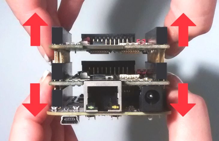
Table of Contents
1  Copyright.........................................................................................................................................................................................................3
2  History..............................................................................................................................................................................................................6
3  Safety................................................................................................................................................................................................................7
4  Overview.........................................................................................................................................................................................................8
    4.1 Features.................................................................................................................................................................................................8
        4.1.1 E1701C CNC Controller Baseboard...............................................................................................................................8
        4.1.2 E1701C LP8 Extension Board...........................................................................................................................................8
        4.1.3 E1701C Digi I/O Extension Board...................................................................................................................................9
5 Position Within The System..................................................................................................................................................................10
6 Boards And Connectors.........................................................................................................................................................................11
    6.1 E1701C CNC Controller Baseboard......................................................................................................................................11
        6.1.1 Ethernet...................................................................................................................................................................................11
                  6.1.1.1 Ethernet Configuration With Windows....................................................................................................12
                  6.1.1.2 Ethernet Configuration With Linux.............................................................................................................12
        6.1.2 USB.............................................................................................................................................................................................13
        6.1.3 Power........................................................................................................................................................................................14
        6.1.4 Power LED...............................................................................................................................................................................14
        6.1.5 User LEDs................................................................................................................................................................................14
        6.1.6 State LEDs...............................................................................................................................................................................15
        6.1.7 Input State LEDs...................................................................................................................................................................15
        6.1.8 microSD-Card........................................................................................................................................................................15
                  6.1.8.1 Firmware Update................................................................................................................................................17
        6.1.9 Stepper motor and control signals................................................................................................................................18
                  6.1.9.1 Referencing sequence.......................................................................................................................................19
        6.1.10 Opto-Configuration..........................................................................................................................................................20
        6.1.11 Extension Connectors.....................................................................................................................................................20
        6.1.12 Reset-Button.......................................................................................................................................................................21
    6.2 E1701C LP8 Extension Board...................................................................................................................................................22
        6.2.1 MO LED....................................................................................................................................................................................22
        6.2.2 Laser Signals...........................................................................................................................................................................22
        6.2.3 Extension Connectors........................................................................................................................................................23
    6.3 E1701C Digi I/O Extension Board...........................................................................................................................................24
        6.3.1 Digi I/O......................................................................................................................................................................................24
        6.3.2 Input State LEDs...................................................................................................................................................................25
7 Quick Start into E1701C........................................................................................................................................................................26
8 Command Interface.................................................................................................................................................................................27
    8.1 General Commands.......................................................................................................................................................................27
9 Programming Interfaces.........................................................................................................................................................................29
    9.1 E1701C Easy Interface Functions...........................................................................................................................................29
        9.1.1 Error Codes.............................................................................................................................................................................43
APPENDIX A – Wiring between E1701C and IPG YLP Series Type B, B1 and B2 fiber laser........................................45
APPENDIX B – Wiring between E1701C and IPG YLP Series Type E fiber laser...............................................................46
APPENDIX C – Wiring between E1701C and IPG YLR Series laser........................................................................................47
APPENDIX D – Wiring between E1701C and JPT YDFLP series fiber laser (“MOPA”) or IPG YLP Series Type D
fiber laser...........................................................................................................................................................................................................48
APPENDIX E – Wiring between E1701C and SPI G4 Pulsed Fibre Laser series................................................................49
APPENDIX F – Wiring between E1701C and Raycus fiber laser..............................................................................................51
APPENDIX G – Wiring between E1701C and MaxPhotonics MFD fiber laser...................................................................52
APPENDIX H – IDC connector pin numbering..................................................................................................................................53
APPENDIX I – Board dimensions............................................................................................................................................................54

                                                                                                                                                                                                                       2
1 Copyright
This document is © by HALaser Systems.
E1701C base- and extension boards, their hardware and design are copyright / trademark / legal trademark of
HALaser Systems.
IPG and other are copyright / trademark / legal trademark of IPG Laser GmbH / IPG Photonics Corporation.
All other names / trademarks are copyright / trademark / legal trademark of their respective owners.
Portions of the E1701 firmware are based on lwIP 1.4.0 (or newer):
Copyright (c) 2001, 2002 Swedish Institute of Computer Science.
All rights reserved.
Redistribution and use in source and binary forms, with or without modification, are permitted provided that
the following conditions are met:
1. Redistributions of source code must retain the above copyright notice, this list of conditions and the
following disclaimer.
2. Redistributions in binary form must reproduce the above copyright notice, this list of conditions and
the following disclaimer in the documentation and/or other materials provided with the distribution.
3. The name of the author may not be used to endorse or promote products derived from this software
without specific prior written permission.
THIS SOFTWARE IS PROVIDED BY THE AUTHOR ``AS IS'' AND ANY EXPRESS OR IMPLIED WARRANTIES,
INCLUDING, BUT NOT LIMITED TO, THE IMPLIED WARRANTIES OF MERCHANTABILITY AND FITNESS
FOR A PARTICULAR PURPOSE ARE DISCLAIMED. IN NO EVENT SHALL THE AUTHOR BE LIABLE FOR ANY
DIRECT, INDIRECT, INCIDENTAL, SPECIAL, EXEMPLARY, OR CONSEQUENTIAL DAMAGES (INCLUDING,
BUT NOT LIMITED TO, PROCUREMENT
OF SUBSTITUTE GOODS OR SERVICES; LOSS OF USE, DATA, OR PROFITS; OR BUSINESS
INTERRUPTION) HOWEVER CAUSED AND ON ANY THEORY OF LIABILITY, WHETHER IN CONTRACT,
STRICT LIABILITY, OR TORT (INCLUDING NEGLIGENCE OR OTHERWISE) ARISING IN ANY WAY OUT OF
THE USE OF THIS SOFTWARE, EVEN IF ADVISED OF THE POSSIBILITY
OF SUCH DAMAGE.
Portions of the E1701 firmware are based on FatFS R0.10a (or newer):
FatFs module is an open source software to implement FAT file system to small embedded systems. This is a
free software and is opened for education, research and commercial developments under license policy of
following terms.
Copyright (C) 2014, ChaN, all right reserved.
• The FatFs module is a free software and there is NO WARRANTY.
• No restriction on use. You can use, modify and redistribute it for personal, non-profit or commercial
product UNDER YOUR RESPONSIBILITY.
• Redistributions of source code must retain the above copyright notice.
Portions of the E1701 firmware are based on StarterWare 2.0 (or newer):
Copyright (C) 2010 Texas Instruments Incorporated - http://www.ti.com/
Redistribution and use in source and binary forms, with or without
modification, are permitted provided that the following conditions are met:
3• Redistributions of source code must retain the above copyright notice, this list of conditions and the
following disclaimer.
• Redistributions in binary form must reproduce the above copyright notice, this list of conditions and
the following disclaimer in the documentation and/or other materials provided with the distribution.
• Neither the name of Texas Instruments Incorporated nor the names of its contributors may be used to
endorse or promote products derived from this software without specific prior written permission.
THIS SOFTWARE IS PROVIDED BY THE COPYRIGHT HOLDERS AND CONTRIBUTORS "AS IS" AND ANY
EXPRESS OR IMPLIED WARRANTIES, INCLUDING, BUT NOT LIMITED TO, THE IMPLIED WARRANTIES OF
MERCHANTABILITY AND FITNESS FOR A PARTICULAR PURPOSE ARE DISCLAIMED. IN NO EVENT SHALL
THE COPYRIGHT OWNER OR CONTRIBUTORS BE LIABLE FOR ANY DIRECT, INDIRECT, INCIDENTAL,
SPECIAL, EXEMPLARY, OR CONSEQUENTIAL DAMAGES (INCLUDING, BUT NOT LIMITED TO,
PROCUREMENT OF SUBSTITUTE GOODS OR SERVICES; LOSS OF USE, DATA, OR PROFITS; OR BUSINESS
INTERRUPTION) HOWEVER CAUSED AND ON ANY THEORY OF LIABILITY, WHETHER IN CONTRACT,
STRICT LIABILITY, OR TORT (INCLUDING NEGLIGENCE OR OTHERWISE) ARISING IN ANY WAY OUT OF
THE USE OF THIS SOFTWARE, EVEN IF ADVISED OF THE POSSIBILITY OF SUCH DAMAGE.
Copyright (c) 2008-2010 Texas Instruments Incorporated. All rights reserved.
Software License Agreement
Texas Instruments (TI) is supplying this software for use solely and exclusively on TI's microcontroller products.
The software is owned by TI and/or its suppliers, and is protected under applicable copyright laws. You may not
combine this software with "viral" open-source software in order to form a larger program.
THIS SOFTWARE IS PROVIDED "AS IS" AND WITH ALL FAULTS. NO WARRANTIES, WHETHER EXPRESS,
IMPLIED OR STATUTORY, INCLUDING, BUT NOT LIMITED TO, IMPLIED WARRANTIES OF
MERCHANTABILITY AND FITNESS FOR A PARTICULAR PURPOSE APPLY TO THIS SOFTWARE. TI SHALL
NOT, UNDER ANY CIRCUMSTANCES, BE LIABLE FOR SPECIAL, INCIDENTAL, OR CONSEQUENTIAL
DAMAGES, FOR ANY REASON WHATSOEVER.
This is part of AM1808 Sitaraware USB Library and reused from revision 6288 of the Stellaris USB Library.
Portions of the E1701 firmware are based on libzint-backend 2.0 (or newer):
libzint - the open source barcode library, Copyright (C) 2008-2017 Robin Stuart
Redistribution and use in source and binary forms, with or without modification, are permitted provided that
the following conditions are met:
1. Redistributions of source code must retain the above copyright notice, this list of conditions and the
following disclaimer.
2. Redistributions in binary form must reproduce the above copyright notice, this list of conditions and
the following disclaimer in the documentation and/or other materials provided with the distribution.
3. Neither the name of the project nor the names of its contributors may be used to endorse or promote
products derived from this software without specific prior written permission.
THIS SOFTWARE IS PROVIDED BY THE COPYRIGHT HOLDERS AND CONTRIBUTORS "AS IS" AND ANY
EXPRESS OR IMPLIED WARRANTIES, INCLUDING, BUT NOT LIMITED TO, THE IMPLIED WARRANTIES OF
MERCHANTABILITY AND FITNESS FOR A PARTICULAR PURPOSE ARE DISCLAIMED. IN NO EVENT SHALL
THE COPYRIGHT OWNER OR CONTRIBUTORS BE LIABLE FOR ANY DIRECT, INDIRECT, INCIDENTAL,
SPECIAL, EXEMPLARY, OR CONSEQUENTIAL DAMAGES (INCLUDING, BUT NOT LIMITED TO,
PROCUREMENT OF SUBSTITUTE GOODS OR SERVICES; LOSS OF USE, DATA, OR PROFITS; OR BUSINESS
INTERRUPTION) HOWEVER CAUSED AND ON ANY THEORY OF LIABILITY, WHETHER IN CONTRACT,
STRICT LIABILITY, OR TORT (INCLUDING NEGLIGENCE OR OTHERWISE) ARISING IN ANY WAY OUT OF
THE USE OF THIS SOFTWARE, EVEN IF ADVISED OF THE POSSIBILITY OF SUCH DAMAGE.
The E1701C baseboard firmware bases on motion5 version 1.1 or newer*:
4Copyright (c) 2018 Oxygenic, (c) 2012-2016 Sungeun K. Jeon for Gnea Research LLC, Copyright (c) 2009-2011
Simen Svale Skogsrud
motion5 is free software: you can redistribute it and/or modify it under the terms of the GNU General Public
License as published by the Free Software Foundation, either version 3 of the License, or (at your option) any
later version.
motion5 is distributed in the hope that it will be useful, but WITHOUT ANY WARRANTY; without even the
implied warranty of MERCHANTABILITY or FITNESS FOR A PARTICULAR PURPOSE. See the GNU General
Public License for more details.
*) GPL notice: the E1701C baseboard firmware is running separately and completely independent from the
main CPU board firmware, they are neither linked nor compiled together with each other. The related motion5
sources can be found at https://sourceforge.net/p/axis5/code/ci/master/tree/
52 History
Date Changes in document
07/2020 Described referencing sequence in detail
03/2020 Clarified wiring of Step/Dir outputs
11/2019 Unsupported command cgcmd removed
10/2019 Funcition description of E1701_set_standby2() added
10/2019 Wiring scheme for MaxPhotonics fiber laser added
10/2019 Example in description of pethd-parameter corrected
03/2019 Added description of flag E1701C_CSTATE_IS_REFERENCING
02/2019 Added “pethd” configuration parameter
11/2018 Initial version
63 Safety
The hardware described within this document is designed to control a laser system. Laser radiation may effect a
person's health or may otherwise cause damage. Prior to installation and operation compliance with all relevant
safety regulations including additional hardware-controlled safety measures has to be secured. The client shall
solely be responsible to strictly comply with all applicable and relevant safety regulations regarding installation
and operation of the system at any time.
Beside of that some laser equipment can be damaged in case it is controlled with wrong signals or signals
outside a given specification. Thus it is highly recommended to check the output generated by this device using
e.g. an oscilloscope to avoid problems caused by wrong configurations. This should be done prior to putting a
system into operation for the first time, whenever some parameters have been changed or whenever any kind
of software update was installed.
The hardware described within this document is also designed to control motors and other electrically driven
tools. Motions caused by these motors and tools may effect a person's health or may otherwise cause damage.
Prior to installation and operation compliance with all relevant safety regulations including additional
hardware-controlled safety measures has to be secured. The client shall solely be responsible to strictly comply
with all applicable and relevant safety regulations regarding installation and operation of the system at any
time.
The hardware described here is shipped without any cover and without prefabricated equipment for electric
installation. It is intended to be integrated in machines or other equipment. It is not for use "as is". Prior to
operation compliance with all relevant electric / electromagnetic safety regulations including additional
hardware-controlled safety measures has to be secured. The client shall solely be responsible to strictly comply
with all applicable and relevant regulations regarding installation and operation of the system at any time.
The hardware described here is an electrostatic sensitive device. This means it can be damaged by common
static charges which build up on people, tools and other non-conductors or semiconductors. To avoid such a
damage, it has to be handled with care and including all relevant procedures (like proper grounding of people
handling the devices, shielding/covering to not to let a person touch the device unwanted, proper packaging in
ESD-bags, ...). For more information please refer to related regulations and standards regarding handling of ESD
devices.
This document describes the E1701C-hardware but may contain errors or may be changed without further
notice.
74 Overview
This document describes the E1701C modular CNC controller board family, their electrical characteristics and
usage. They consist of E1701C 5-axis CNC controller baseboard plus optional extension board. Special variant
E1701M is no CNC controller and therefore not covered by this document.
The E1701C CNC controller boards are designed for controlling motion-stage based stepper motor systems
with two to five axes. Depending on the used extension boards (which are optional) they also supply extensive
signals for laser and external control. The communication between the host system and the controller boards is
done via Ethernet or USB.
When using E1701C CNC controller boards, there is always one baseboard required for proper operation. This
baseboard can be used together with different extension boards that provide additional signals for controlling
the laser marking process. These extension boards are optional and have to be used only in environments
where the additional signals processed by these boards are required. So depending on used type of laser and
requirements, the minimal solution to control a laser marking system may consist of the baseboard only.
An E1701C baseboard can be combined with several extension boards of different types but never with more
than one board of same type.
4.1 Features
Following the features of available base- and extension boards are described
4.1.1 E1701C CNC Controller Baseboard
This baseboard can be used to control XY-tables, CNC-mills, XY/XYZ-stages or similar, stepper-motor driven
devices. It can be combined with different extension boards without any restrictions as long as only one
extension of same type is used at the same time. The E1701C baseboard offers following features:
up to 5 stepper axes controllable via step and direction signals
combined CNC motion of 2..5 axes
can use lasers as well as many other tools for material processing/milling
up to 38 kHz maximum step frequency (jitter-free)
100 Mbit Ethernet connection
USB 2.0 connection
command execution time down to 0,5 microseconds
realtime processing of laser and motion signals
can control nearly every laser type (this may require extension boards as described below)
512 MByte DDR3 RAM
1 GHz CPU main clock plus 3 parallel running, additional CPU cores/MCUs
support for microSD and microSDHC cards
internal command and vector data list with more than 17 million entries
continuous list concept, no need to swap between buffers
BeamConstruct PRO license included
4.1.2 E1701C LP8 Extension Board
This board can be used to provide signals for controlling a wide range of laser types. It offers following features:
LP8 8 bit CMOS level parallel digital output e.g. for controlling laser power
LP8 latch CMOS level digital output for usage with IPG(tm) and compatible laser types
Master Oscillator CMOS level digital output for usage with IPG(tm) and compatible laser types
8 bit 0..5V analogue output e.g. for controlling laser power (this output is a slave of LP8 outputs)
two laser CMOS level digital outputs for usage with YAG, CO2, IPG(tm), SPI(tm) and compatible laser
types (outputs can provide PWM frequency, Q-Switch, FPK-pulse, CW/continuously running
frequency, stand-by frequency) running with frequencies of up to 20 MHz
84.1.3 E1701C Digi I/O Extension Board
This board provides additional digital in- and outputs for synchronisation and communication with external
equipment. It offers following features:
8 freely usable digital outputs providing either CMOS level or electrically insulated outputs via
external power supply
8 freely usable digital inputs expecting either CMOS level or electrically insulated inputs via external
power supply
95 Position Within The System
The E1701C CNC controller system can be connected to the host via Ethernet or USB to receive processing
data from BeamConstruct laser marking application, from ControlRoom process control software or from any
other application which makes use of one of the provided programming possibilties (as described below). When
using Ethernet connection, it optionally can be connected via USB too. In this case USB connection is only used
to retrieve BeamConstruct PRO license from the board:
Since 100 Mbit Ethernet provides much faster data transfer than USB 2.0, this connection type is preferred.
Especially in case complex processing data with many short lines that result in many separate jump and mark
commands are used, Ethernet connection is more responsive.
When using USB connection with such data, time from sending data to the card until marking operation can be
started may be longer, caused by slower USB data transfer:
In both cases the board itself is connected with the stepper motors via separate power drivers to submit fully
synchronous 2D, 3D or 4..5 axis movement information to it. Beside of that it is connected to a laser or any
other tool to submit motion-synchronous data. Additional communication channels between the E1701C CNC
controller board and a connected machine can be done via separate IOs of an extension board.
106 Boards And Connectors
6.1 E1701C CNC Controller Baseboard
The E1701C 5-axis CNC Controller Baseboard provides following connectors and interfaces:
1. Ethernet – for communication with the host system, motion and processing information are submitted
via this path
2. USB – via miniUSB connector for providing BeamConstruct PRO license to host system and optionally
for submitting processing data from host to E1701C card (in case Ethernet is not used)
3. Power – connect with power jack 5V DC
4. Power LED – lights when power is available
5. User LEDs – show operational and error states of card
6. State LEDs – show motion and tool/laser modulation states
7. Input state LEDs – 5 LEDs showing current state of limit inputs
8. microSD-card (on bottom side) – storage place for firmware and extended configuration file, can be
used to upgrade firmware, to change the card's IP and other things more
9. Stepper motor and laser/tool signals – white 26 pin laser and motion signal output connector
10. Opto-Configuration - choose operation mode for limit-inputs
11. Extension connectors – extension boards can be placed here in order to add some more functionality
and hardware interfaces to the board
12. Reset-button – on-board button to restart the board completely
6.1.1 Ethernet
This is a standard RJ45 Ethernet plug for connection of the board with the host system. The controller board is
accessed via this connection, all motion and laser data are sent via Ethernet. Thus it is recommended for
security reasons to have a separate 1:1 connection from the host to the CNC controller card by using a separate
Ethernet port. In case this is not possible, at least an own, physically separated sub-net for all controller cards
should be set up. This network of course should be separated from normal network completely.
Ethernet connection is initialised once during start-up, thus Ethernet cable connecting E1701C board and host
system needs to be plugged before the board is powered up.
By default the E1701C baseboard is using IP 192.168.2.254, thus the Ethernet network the card is connected
to needs to belong to subnet 192.168.2.0/24.
PLEASE NOTE: For security reasons it is highly recommended to not to mix a standard communication network
with an E1701C network or to connect the CNC controller card with a standard network. Here it may be
possible someone else in that network (accidentally) connects to that CNC controller and causes motion
operations and/or laser emission.
The IP of the controller can be changed. This is necessary e.g. in case an other subnet has to be used or in case
the E1701C board has to be operated in multi-controller environments where more than one card will be
11accessed at the same time. The IP can be configured using e1701.cfg configuration file that is located on
microSD-card. To change the IP please perform the following steps:
1. disconnect E1701C board from power and USB
2. remove microSD-card
3. put microSD-card into a desktop computer, this may require a microSD- to SD-card-adapter
4. open the drive that is assigned to the card
5. open file e1701.cfg using a text editor like Notepad, KWrite or MousePad
6. add a line or edit an existing line "ip1=", here the desired IP has to be appended (as example: when you
want to configure IP 192.168.2.13 the line has to be "ip1=192.168.2.13" – without any quotation
signs
7. save the file
8. eject the drive the card is assigned to
9. place the microSD-card in E1701C board (place without the use of force, notice correct orientation
with connectors of microSD-card to bottom!)
10. power up card
When User LEDs do not light up as described below, please check if microSD-card is placed in board correctly.
6.1.1.1 Ethernet Configuration With Windows
When E1701C CNC controller is accessed via Ethernet, it is recommended to have a 1:1 connection to the host
PC for security reasons. Since the controller is working with a static IP (default is 192.168.2.254) the Ethernet
port on host PC has to be configured with an IP of same subnet in order to allow access to it. For Windows 7
(and similar) this configuration has to be done using following steps:
1. select “Start”-button and choose entry “Control Panel”
2. Select “Network and Sharing Center”
3. Select “Change adapter settings” in upper left corner
4. find the network interface E1701C has to be connected with and select it
5. find entry “Internet Protocol Version 4 (TCP/IP4)”
6. select it and press button “Properties”
7. now a window opens that has to be configured as follows:
There you can specify an IP for your host PC. It has to belong to network 192.168.2.xxx and can be any
number except than 192.168.2.254 (this is already the IP of the CNC controller card), 192.168.2.0 or
192.168.2.255.
6.1.1.2 Ethernet Configuration With Linux
When E1701C CNC controller is accessed via Ethernet, it is recommended to have a 1:1 connection to the host
PC for security reasons. Since the controller is working with a static IP (default is 192.168.2.254) the Ethernet
12port on host PC has to be configured with an IP of same subnet in order to allow access to it. For Linux (with
NetworkManager) this configuration has to be done using following steps:
1. right-click the network-symbol in taskbar
2. click "Edit Connections..."
3. select the "Wired" network interface the CNC controller card is connected with and press button
"Edit"
4. go to tab-pane "IPv4 Settings" and configure it as shown below:
There you can specify an IP for your host PC. It has to belong to network 192.168.2.xxx and can be any
number except than 192.168.2.254 (this is already the IP of the CNC controller card), 192.168.2.0 or
192.168.2.255.
6.1.2 USB
This is a standard miniUSB-connector for connection of the board with the host system. It is used to retrieve
BeamConstruct PRO license and optionally – when Ethernet is not connected – to send processing data to the
card.
PLEASE NOTE: USB 2.0 is much slower than a standard 100 Mbit Ethernet connection, so expect slower
execution in case of complex processing data!
The required device driver is installed together with OpenAPC-setup (Windows) or comes with operating
system by default (Linux). E1701C card appears as COM-interface on Windows using any free number for the
port. With Linux it appears as /dev/ttyACMx where "x" is any number. These numbers are provided by the
operating system automatically.
By default USB provides 5V power supply too. So whenever card has to be stopped, both USB and power have
to be disconnected in order to shut it down completely. It is not recommended to use USB as power supply, an
additional, external power should be connected in order to operate E1701C controller correctly. Nevertheless
it might be possible E1701C card can be operated on USB power only. Since this highly depends on the
capabilities of used host system, it has to be evaluated for every particular case.
When the controller is connected via USB, a BeamConstruct PRO license is provided via this interface
automatically. This is done without the need to configure anything, and as long as following conditions are true:
• physical USB connection from controller to host PC exists
• the COM-port (Windows) has a number smaller than COM20
• the controller is working and the Alive-LED in blinking
13It is also possible to have the USB-connection for license retrieval only and to use the Ethernet-connection to
transfer marking data to the controller, both can exist beside each other.
6.1.3 Power
Power supply for E1701C CNC controller board is done via power jack right beside Ethernet port. Power can
be supplied via a 2.1 mm x 5.5 mm centre connector when connected to a positive power supply rated at 5V DC
+/- 0.1V and 2.5A (smoothed, positive pole on inner contact). Do not apply voltages in excess of 5V to the DC
input. The DC power supply must be grounded.
To avoid high frequency interferences from other electrical equipment or from within the power supply, it is
recommended to place a ferrite bead at the cable close to the board. Please also check for correct shielding in
respect to the equipment the E1701C card is used within.
6.1.4 Power LED
This led is lit as soon as the board is on some power. This means it may be functional and could emit any signals
as soon as this LED is on, but it does not necessarily need to work properly since firmware may not be started at
this point. Please refer section “6.1.5 User LEDs” below for LEDs that show functional state of the board.
6.1.5 User LEDs
The real operational state of the card is shown by four additional LEDs described here from inner to outer
position:
1. Boot- and Alive-LED – this LED is turned on permanently as soon as the card was powered up and the
firmware boots properly. When it is not turned on after some seconds, please check if the microSD-
card is placed properly and if it contains a working firmware file (for details please refer below). After
boot process has completed successfully, it starts blinking slowly. This is an alive-notification, as long as
it blinks, the board is working and ready for operation. During operation the blink frequency may
change. Only in case it does not blink for more than 10 seconds, the board has died for some reason and
should be restarted.
2. Processing Active LED – this LED is turned on as long as an operation is running. This LED does not
correspond to the tool on-off/laser gate signal, comparing to it it’s also enabled during jumps or wait-
cycles when laser is turned off but processing itself is active.
3. Stop LED – this LED is lit as long as a valid external stop signal is detected.
4. Error-LED – this LED is turned on in case a fatal error occurs that normally should never happen. When
it is on, in most cases board can't continue with operation until the reason for error is removed and the
board is restarted. In case this LED is turned on please:
- check if you are using exactly one baseboard
- check if you are using E1701C extension boards only (and no other 3rd party hardware)
- check if you are using latest firmware and host software
- check all connections and cables
- undo your latest changes in hardware and configuration
If these steps do not help, please contact HALaser Systems for further assistance.
146.1.6 State LEDs
These LEDs show the current motion and marking/milling state of the controller. The inner, yellow LED is
turned on as long as a motion is running.
The outer, red LED shows the modulation state of the laser/the activation state of the connected tool and signal
of laser gate output. It is turned on as long as the laser/the tool is turned on and the laser gate output high. This
LED does NOT signal the same like the Processing Active LED described above since it will be turned off during
jumps.
6.1.7 Input State LEDs
These 5 yellow LEDs show the state of corresponding 5 digital reference inputs. As long as a HIGH signal is
detected on an input, the related LED is turned on. These LEDs can be used to check if a reference input “Ref” is
at high:
For a description of these inputs, please refer to section “6.1.9 Stepper motor and control signals” below.
6.1.8 microSD-Card
The microSD card is storage place for firmware and configuration files. Here SD and SDHC cards with a
maximum capacity of up to 32 GB are supported.
To remove the microSD-card, first disconnect all power from the E1701C board completely (including USB, the
Power LED has to go off). Next press microSD card gently into the board until you can hear a click-noise. Then
you can pull it out of the board. To place a microSD card, the same has to be done in reverse order: place it into
the E1701C board’s card slot and press it gently until a click-noise signals locking of the card. Now the board
can be powered.
E1701C baseboard is shipped with a card containing firmware and configuration files:
e1701.fwi - firmware file that is used to operate the board, to be replaced when a firmware update is
provided
e1701.cfg - configuration text file, can be edited using a text editor in order to modify cards
configuration
e1701.dat – additional data file that is used to operate the board, to be replaced when a firmware
update is provided
To use an other microSD card than the one shipped with the board, following conditions have to be met:
• maximum total size of 32 GB (SD or SDHC card)
• FAT32 formatted
• using only one partition
• BOOT-flag is set
• E1701.fwi and e1701.dat file available on card
15An additional file E1701.cfg can be placed on the card too. It contains plain ASCII text, acts as configuration file
and can contain several parameters and its values which are separated by an equal-sign. Every of the possible
parameter/value pairs has to be located in an own line. Following configuration parameters are possible within
this file:
Parameter Description Example
ip1 Configures IP of Ethernet port. Here only IPs in xxx.xxx.xxx.xxx ip1=192.168.2.100
notation are allowed but no host or domain names. specifies IP 192.168.2.100
to be used for Ethernet
interface on next startup
passwd Specifies an access password that is checked when card is passwd=myCardPwd
controlled via Ethernet connection. This password corresponds set a password
to password specified with function "myCardPwd"
E1701C_set_password(), please refer below for a detailed
description.
When a client computer connects to the card without sending
the correct password, Ethernet connection to this host is closed
immediately.
PLEASE NOTE: this password does not replace any network
security mechanisms and does not give the possibility to operate
E1701C controller via insecure networks or Internet! It is
transferred unencrypted and therefore can be "hacked" easily.
Intention of this password is to avoid collisions between several
E1701C cards that operate in same network and are accessed by
several software instances.
Maximum allowed length of the password is 48 characters. It is
recommended to not to use any language-specific letters.
mipout Configure a Digi I/O output pin to be used as “mark in progress”- mipout=1
signal by default; here an output bit number in range 0..7 has to use DOut1 for mark-in-
be configured which will be set to HIGH as long as an operation is progress signal
in progress, the value given here can be overwritten by API-
function E1701C_digi_set_mip_output()
wetout Configure a Digi I/O output pin to be used as “wait for external wetout=0
trigger”-signal by default; here an output bit number in range 0..7 use DOut0 for mark-in-
has to be configured which will be set to HIGH as long as an progress signal
operation is in progress and the controller is waiting for an
external trigger signal to arrive at ExtStart input, the value given
here can be overwritten by API-function
E1701C_digi_set_wet_output()
digiinit Initialises the digital outputs on firmware start-up with the given digiinit=2
defaults. This overrides the hardware defaults. The default set DOut1 to HIGH initially
digital values set here are NOT available on power up but a few and all other outputs to
seconds later after firmware has been loaded and started. LOW
This function requires firmware version 32 or newer.
digimask Masks the digital inputs and specifies which inputs can be read. digimask=253
All input bits which are ignored by this command by setting the use only DIn2..DIn7 as
related value to 0, are no longer read. This may be useful for input and ignore DIn0 and
applications where encoder inputs are used together with a DIn1
IOSelect stand-alone operation and where the random state of
the encoder has to be masked out.
This function requires firmware version 32 or newer.
digidebc Sets a debouncing time / filter time for the digital inputs of the digidebc=10
Digi IO extension board in order to not to let the inputs react on set the debounce-time to
noise or bouncing of mechanical inputs. The debouncing value is 310 usec
given in time-units where every time-unit is equal to 31 usec. By
default 7 time-units are set.
16Parameter Description Example
fastdebc Sets a debouncing time / filter time for the ExtStart and ExtStop fastdebc=10
inputs in order to not to let the inputs react on noise or bouncing set the debounce-time to
of mechanical inputs. The debouncing value is given in time-units 310 usec
where every time-unit is equal to 31 usec. By default 7 time-units
are set.
tune1 Enables special functions and features that are not activated by tune=9
default. As parameter a number can be handed over that disables ExtStart input and
specifies the functions to be enabled. Following numbers can be switches over external
concatenated by adding them: trigger function to DIn7
input and inverts the logic
1 – use DIn7 of Digi I/O Extension Board as external trigger, this of the LaserGate output
disables ExtStart input of E1701C Baseboard and LP8 Extension
Board
8 – invert LaserGate output to work as active HIGH signal; when
this option is set, logic of LaserGate-LED changes too, it is on as
long as laser is turned off and it is off as long as laser is on
16 – invert LaserA output of LP8 extension to work as active
HIGH signal
32 – invert LaserB output of LP8 extension to work as active
HIGH signal
32768 – invert the mark-in-progress signal of Digi I/O extension
65536 – invert the wait-external-trigger signal of Digi I/O
extension
usb When this parameter is set to 0, USB interface is disabled usb=0
completely. This means it is no longer possible to connect to turn off USB interface
E1701C USB serial interface via terminal software or via
BeamConstruct and it is also no longer possible to retrieve
BeamConstruct PRO license via USB. This option can be used to
suppress illegal access to USB and saves some power.
eth When this parameter is set to 0, network interface is disabled eth=0
completely. This means it is no longer possible to connect to turn off Ethernet interface
E1701C via Telnet or via BeamConstruct. This option can be
used to suppress illegal access to Ethernet, to save several
seconds of startup-time and some power.
pethd When Ethernet connection is used, it has to be established on pethd=20 - halt
power-up of the controller card as this connection is set-up and initialisation of the
configured by the controller only once during boot. There may be controller for about 10
situations where the other side of the Ethernet connection can seconds prior to
not boot up as fast as E1701. In such cases this parameter can be initialisation of Ethernet
used. It delays initialisation of Ethernet by the time given as interface
parameter. The time is specified in unit “delayticks” where one
“delaytick” is equal to about 0,5 seconds.
As long as the controller is halted during initialisation due to this
parameter, this is signalled by the Stop-LED (please refer to 6.1.5
User LEDs for details).
This feature requires a firmware version 34 or newer.
6.1.8.1 Firmware Update
As described above the firmware is located on microSD-Card and therefore can be updated easily:
1. remove the microSD-Card as described above
1
172. download a new firmware from https://openapc.com/download/Firmware/E1701 (the higher the
number in the file name, the newer the firmware is)
3. copy the contents of this ZIP-file to microSD-Card (please take care about e1701.cfg in case it contains
a changed configuration)
4. reinsert microSD-Card as described in previous section
6.1.9 Stepper motor and control signals
The white 26 pin connector provides several signals to control up to five stepper motor axes and connected
tools which can be a laser or any other tool that is able to deal with the related signal. The connector is a white
one to avoid confusion when a LP8 Extension Board is used too. This connector provides following signals:
Upper Signal Voltage Remarks Lower Signal Voltage Remarks
Row Of Row Of
Pins Pins
1 Unused, do not connect! 2 5V 5V
3 RefX CMOS, 0/5V Reference 4 RefY CMOS, 0/5V Reference
or 0/Vext inputs or 0/Vext inputs
5 RefZ CMOS, 0/5V 6 RefA CMOS, 0/5V
or 0/Vext or 0/Vext
7 RefB CMOS, 0/5V 8 Do not connect!
or 0/Vext
9 GNDext GND External 10 GND GND Board-
ground internal
Ground
11 Unused, do not connect! 12 Unused, do not connect!
13 ExtStop 5V Input 14 ExtStart 5V Input
control control
signal signal
15 StepX 5V Stepper 16 DirX 5V Stepper
17 StepY 5V pulse 18 DirY 5V motor
19 StepZ 5V output 20 DirZ 5V direction
21 StepA 5V signals 22 DirA 5V output
23 StepB 5V 24 DirB 5V signals
25 LaserGate 5V 26 PowerRamp 5V PWM
GNDext depends on opto-configuration as described below. In opto-insulated mode (opto-configuration jumper
not set) external ground has to be connected to this input. Then RefX..RefB work in respect to this external
power add van be driven with an Vext of up to 24 V. This is true for the reference inputs only, all other inputs
remain with 0/5V logic levels and can't be driven with any external power.
WARNING: When no opto-insulated mode is selected (opto-configuration jumper is set), do NOT FEED ANY
EXTERNAL POWER into Ref-inputs except the one from 5V output (pin 2), otherwise this would cause damage
to the E1701C board!
The pins 15..24 provide the stepper motor control signals for axes 0..5 (step/direction signals to be used with a
separate, external power driver). They operate in open collector mode and have to be wired as follows:
18Here “Step/Dir” symbolises one of the digital outputs StepX, StepY, StepZ, StepA, StepB, DirX, DirY, DirZ,
dirA,DirB. V+ is either V (5V internal, non-insulated mode) or Vext (up to 24V external, insulated mode). GND is
either GND (non-insulated mode) or GNDext (insulated mode). The internal resistor of the connected device is
not allowed to have less than 1600 Ohms (at 24V) or 330 Ohms (at 5V) in order to not exceed the given current
limits as specified below.
The pins 3 to 7 are input pins for axes 0..5 to be used with the reference/homing position.
Laser Gate provides laser modulation signal, turns on the laser during marks and off during jumps.
PowerRamp is a signal which can be used for power-ramping applications: it provides a 9,75 kHz PWM signal
which is proportional to the current nominal speed (according to the target maximum speed) and typically
varies during acceleration and deceleration phases. It can be used either directly as PWM signal or with an
additional capacity as analogue signal to modulate the power of a laser. For a variable PWM frequency the
LaserA output of the LP8 extension board (“6.2 E1701C LP8 Extension Board”) has to be used.
Maximum current to be pulled out of each of the outputs is 15 mA.
ExtStart expects a CMOS-level input signal in respect to GND and can be used as external trigger signal to start
operations when a HIGH-signal is detected at input pin.
ExtStop expects a CMOS-level input signal in respect to GND and can be used as external stop-signal in order
to stop a running marking operation by using a HIGH-signal at input pin.
6.1.9.1 Referencing sequence
As the E1701C CNC controller makes use of external stepper motors which can’t persist and provide the
current position, prior to first use (after power-up) or when the motion position was changed manually and
without the controller involved, all axes should be referenced in order to find a defined starting point. For this a
referencing sequence has to be started either via the related API function call (please refer to section “9.1
E1701C Easy Interface Functions”) or via suitable software. When started, a referencing sequence consists of
the following steps:
1. move to the limit switch until it is hit (can be signalled either by LOW or HIGH input level, dependent
on current configuration) using the first referencing speed
2. leave the limit switch until the leave distance has elapsed and using a lower speed; when the switch
can’t be left any more within a reasonable time, referencing fails and is cancelled at this point
3. move again to the limit switch until it is hit (can be signalled either by LOW or HIGH input level,
dependent on current configuration) using the second referencing speed
4. leave the limit switch until the leave distance has elapsed and using a lower speed; when the switch
can’t be left any more within a reasonable time, referencing fails
When the referencing cycle has completed successfully, the controller sets the related axis position to value -1
(which can be changed to any other, suitable value by the controlling software). Now all movement operations
can be done in relation to this fixed, defined position.
19When the referencing cycle could not be completed successfully, the axis positions are undefined and should
not be used for any motion operations!
6.1.10 Opto-Configuration
Using this jumper the operation mode for reference inputs RefX..RefB can be chosen. When is is set, the opto-
couplers are powered internally. In this mode it is not working in opto-insulated mode and I/Os are using CMOS
level signals.
When it is not set, external ground has to be provided at GNDext pin of the 26 pin connector (as described
above) and the reference inputs are working in electrically insulated, opto-coupled mode with input signal
levels in range 5V..24V.
This opto-insulated mode applies ONLY to the reference inputs, all other signals including step/direction signals
to stepper motor driver are not separated and need to be operated with an external galvanic separation when
this is required.
6.1.11 Extension Connectors
The two extension connectors on each side of the board can be used to place extension boards with additional
peripheral interfaces. The extension connectors are designed to place/remove boards from time to time but
they are not intended for constant hardware changes. So changing extension boards repeatedly and often e.g.
as permanent part of a production process is not recommended.
Key pin closed on lower connector and missing in upper board to ensure correct orientation
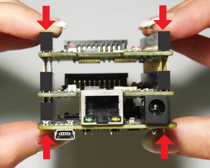
PLEASE NOTE: when placing a new extension board
1.check correct orientation and position of the key pin which is closed in connector
2.place the pins of the extension boards onto the extension connectors exactly
3.move down the extension board by pressing on its extension connectors gently; DO NOT PRESS THE BOARD
ITSELF BUT ONLY THE CONNECTORS!
20PLEASE NOTE: When removing an extension board DO NOT pull on the extension connectors but hold both
boards on their long side directly at the PCBs edges:
Due to of the large number of pins, it is easy to plug in an extension but more difficult to pull it out. So when
removing an extension board, it is recommended to be very slow and to carefully pull each side up just a little bit
to avoid bending of the pins as they exit.
6.1.12 Reset-Button
When this button is pressed for at least 20 milliseconds, it restarts the card completely, a current operation is
cancelled, all signals are disabled and all remaining processing data are dropped. After releasing this button, the
board is rebooted and firmware is started again.
216.2 E1701C LP8 Extension Board
The E1701C LP8 Extension Board provides following features:
1. MO LED – shows state of Master Oscillator output
2. Laser signals – black 26 pin laser output connector which provides signals for controlling a laser
3. Extension connectors – more extension boards can be placed here in order to add some more
functionality and hardware interfaces to the board, please refer to related section in description of
baseboard above
6.2.1 MO LED
This LED is specific to the Master Oscillator output signal described below. As long as the signal is on (HIGH-
signal at output pin), the LED is turned on.
6.2.2 Laser Signals
The black 26 pin connector provides several signals for controlling a laser source. It can be used e.g. together
with YAG, CO2, IPG™, fiber and compatible lasers since it provides additional signals and frequencies these laser
types may require for proper operation. To avoid confusion with similar connector used on E1701C Base board
this connector is black.
This connector provides the following signals:
22Upper Signal Voltage Remarks Lower Signal Voltage Remarks
Row Of Row Of
Pins Pins
1 LP8_0 CMOS, 0/5V, 2 GND GND
max 8 mA
3 LP8_1 CMOS, 0/5V, 4
max 8 mA
5 LP8_2 CMOS, 0/5V, 6 5V 5V
max 8 mA
7 LP8_3 CMOS, 0/5V, 8 MO CMOS, 0/5V, Master
max 8 mA max 8 mA Oscillator
9 LP8_4 CMOS, 0/5V, 10 AOut0 0..5V, max 15 Analogue
max 8 mA mA output
11 LP8_5 CMOS, 0/5V, 12
max 8 mA
13 LP8_6 CMOS, 0/5V, 14
max 8 mA
15 LP8_7 CMOS, 0/5V, 16
max 8 mA
17 LP8 CMOS, 0/5V, 18 5V 5V
Latch max 8 mA
19 LaserB CMOS, 0/5V, FPK 20 Connected to
max 14 mA pin 21
21 Connected to 22 LaserA CMOS, 0/5V, PWM,
pin 20 max 14 mA frequency or Q-
Switch
23 GND GND 24
25 5V 5V 26 Laser CMOS, 0/5V,
Gate2 max 14 mA
LP8_0...LP8_7 provide parallel 8 bit output signal (e.g. for power control with IPG(tm)/fiber lasers, waveform
selection for SPI(tm) lasers and other).
LP8 Latch pin signals valid output at LP8_0..LP8_7 and AOut0 by submitting a latch pulse of software-
controlled length.
MO can be used to enable master oscillator (e.g. for IPG(tm)/fiber lasers or compatible).
LaserA usage depends on software configuration and control, it is able to output a pulse-width modulated
frequency (e.g. for controlling CO2 lasers), CW/continuously running frequency (e.g. for fiber lasers) or Q-
Switch signal (e.g. for YAG lasers) in range 25 Hz..20 MHz.
LaserB can be used for emitting a FPK pulse (e.g. for YAG lasers).
AOut0 pin provides unipolar analogue output for controlling e.g. laser power or additional equipment. This
output is a slave of LP8_0..LP8_7 output, they are electrically connected and therefore can’t have different
values and can’t be controlled by software independently. So when LP8 outputs are all LOW, AOut0 is on 0V.
When LP8 outputs are all HIGH, AOut0 is 5V.
PLEASE NOTE: output of 5V at AOut0 depends on the used power supply. So in case board is powered via USB
and USB power supply delivers less than 5V, maximum output on AOut0 will be less than 5V too. Here is would
be recommended to use the base board with an external power supply that feeds exactly 5V into it.
6.2.3 Extension Connectors
The two extension connectors on each side of the board can be used to place extension boards with additional
peripheral interfaces. For a description of handling and usage of these connectors please refer above.
2 requires hardware-revision 1.1 or newer
236.3 E1701C Digi I/O Extension Board
The E1701C Digi I/O Extension Board provides following features:
1. Digi I/O – electrically insulated digital in- and outputs
2. optional inputs for 90 degree phase shifted encoders to be used with marking on-the-fly operations
3. Opto-Configuration – choose operation mode for Digi I/Os
4. Input state LEDs – displaying of HIGH/LOW state of used inputs
In case more extension boards are used on E1701C, Digi I/O extension always has to be placed on top.
6.3.1 Digi I/O
The 20 pin connector provides 8 lines for input and 8 lines for output of digital signals that can work on CMOS
level (non-insulated mode) or via opto-couplers (electrically insulated mode with external power supply)
optionally. The operation mode depends on jumper settings described below. The connector is used as follows:
24You can also read