QUATTROCONE Catalog 2021/22 - IPS IMPLANT SYSTEMS - QUATTROCONE - Straumann
←
→
Page content transcription
If your browser does not render page correctly, please read the page content below
QUATTROCONE

 IPS
IMPLANT SYSTEMS

QUATTROCONE
Catalog 2021/22

Thank you for your trust

2
System description
The QUATTROCONE implant                                4

The QUATTROCONE30 implant                              6
  QUATTROCONE30 - QuattroFix                           8
  Implant diameters and lengths                       10
  Implant connections                                  11

Continuity of emergence profile                       11

Drills12

Conventional treatment planning                       15

Drill stops and combination tables                    16

Computer-aided treatment planning with MedentiGuide   18

Surgical tray                                         20
  Surgical tray layout diagram                        22

Surgery washing tray                                  24
  Surgery washing tray layout diagram                 26

The new placement instrument                          31

Torque ratchet surgical                               31

The drilling protocol                                 34

QUATTROCONE35
 Implant bed preparation                            35
 Implant insertion                                  36
 Option 1: Transgingival healing                    37
 Option 2: Submerged healing								 38
 Option 3: Immediate restoration with a provisional 39

QUATTROCONE3040
 Implant bed preparation 40
 Implant insertion       41
 Inserting the abutment  42

Clinical examples of QuattroFix                       44

Science46

Product catalog
Surgery50

Prosthetics 											 75

Prosthetic tools                                      95

Accessories98
                                                             3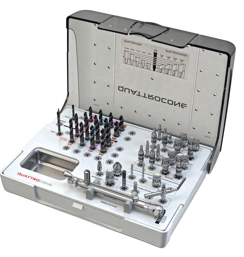
The QUATTROCONE implant
Primary stability
Bone preserving
High precision conical connection between implant and
abutment
SURFACE
The highly pure, sand-blasted and acid-etched surface extends the
entire length of the implant to the machined implant shoulder. It
possesses macro-micro roughness that is ideally dimensioned for
the deposition of bone-forming cells and thus enhances the ideal
and above all reliable long-term osseointegration of the implant.
It ensures well above average crestal bone formation in conjunction
with the coronal microthread and the conical interface, throughout
the implant shoulder to the interface.
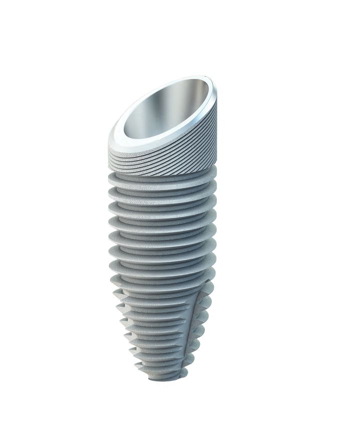
FORM
The body of the QUATTROCONE implant is root shaped and, in
combination with a high-profile thread and three cutting edges,
ensures high primary stability, even in challenging situations. Per-
fect for immediate implant placement and immediate loading.
4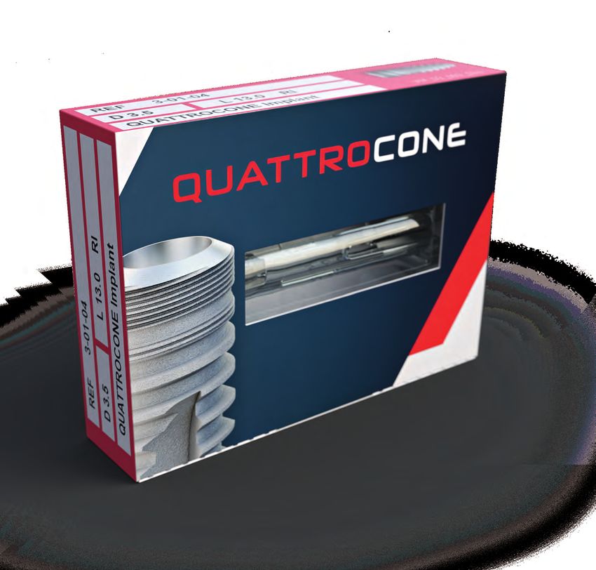
CRESTAL MICROTHREAD
                    The crestal microthread may promote the
                    permanent apposition of bone cells and
                    their retention in the crestal region. With
                    subcrestal insertion, in combination with
                    the high precision conical inner connec-
                    tion, it produces apposition of the bone
                    past the shoulder to the interface.

                    MACROTHREAD
                    Very high primary stability in all bone con-
                    ditions with newly developed high-profile
                    thread. It is self-tapping and gentle on the
                    bone while still exhibiting extremely high
                    primary stability. The thread pitch of 1 mm per
                    rotation reduces insertion times.

IMPLANT CONNECTION
The high precision friction-locked and keyed interface achieves the best
possible levels of stability between the abutment and the implant.

1.   One identical conical connection between the implant and abut-
     ment for all QUATTROCONE implant diameters.

2.   The conical connection between the implant and the abutment is
     virtually free from micromovements. As a result of this no mechan-
     ical irritations arise and the retention of the peri-implant bone is
     positively influenced.

3.   The connection is almost bacteria and liquid proof and can reduce
     the risk of infection. It supports the development of healthy tissue
     that is not irritable and prevents bone depletion.

4.   Integrated system-linked platform switching shifts the transition
     between the implant and the abutment from the implant shoul-
     der to a central position. This keeps bacterial stimuli away from the
     peri-implant tissue in conjunction with the tight conical connec-
     tion and creates a broad horizontal basis for the stable apposition
     of hard and soft tissue.

5.   In conjunction with a subcrestal implant position and the coronal
     microthread section, the implant abutment connection meets all
     system requirements for permanent red-white esthetics.

                                                                             5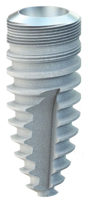
The QUATTROCONE30 implant
    Specially developed and patented for the QuattroFix*
    treatment concept and all indications with angled implant
    insertion.

    SURFACE
    The high purity, sand-blasted and acid-etched surface extends the
    entire length of the implant to the (machined) implant shoulder.
    It possesses macro-micro roughness that is ideally dimensioned
    for the deposition of bone-forming cells and thus enhances the
    ideal and above all reliable long-term osseointegration of the
    QUATTROCONE30 implant. It ensures well above average crestal
    bone formation in conjunction with the coronal microthread and
    the conical interface, throughout the implant shoulder to the
    interface.

                             FORM
                             The body of the QUATTROCONE30 implant extends in a root
                             shaped pattern and, in combination with a high-profile thread and
                             three cutting edges, ensures high primary stability, even in chal-
                             lenging situations. Perfect for immediate implant placement and
                             immediate loading.

                     MACROTHREAD
                     The macrothread geometry has been developed for a 30°
                     inclined position. 30° thread flanks ensure optimal trans-
                     fer of forces in the bone. No implant tilting.
                     Thread pitch reduced to 0.60 mm per rotation enables
                     precise vertical positioning and rotational alignment of
                     the implant body in the bone and guarantees very high
                     primary stability.

6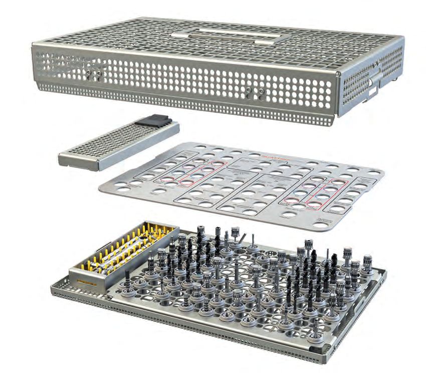
IMPLANT SHOULDER 30°
                                        Shoulder angled at 30°. For final
                                        positioning flush with the bone
                                        when positioned at a 30° angle with
                                        QuattroFix*.

                                             MACROTHREAD

                                                                                             MICROSTRUCTURE
                                                                                             Crestal micro-groove structure.
                                                                                             For long-term bone preservation
                                                                                             with the QuattroFix*.

                                         IMPLANT CONNECTION
                                         Specially developed, very deep primary
                                         conical implant connection distributes
                                         the forces applied at a 30° angle deep into
                                         the implant and ensures high mechanical
                                         stability reserves. Malpositioning of the
                                         abutment is impossible as there is only one
                                         single possible rotational position.

* QuattroFix is a special treatment concept for fixed, full-arch restoration for edentulous patients with an atro-             7
  phic alveolar ridge on two straight and two 30 degree-angled implants.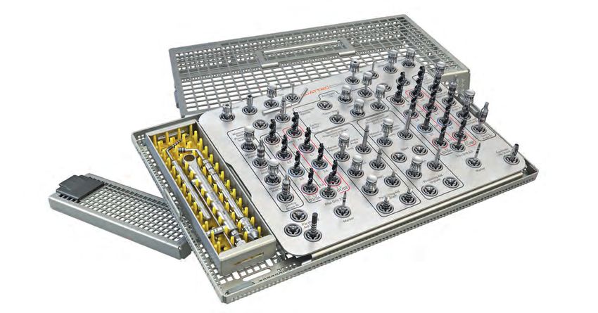
QUATTROCONE30 - QuattroFix
    QuattroFix is a special concept for fixed, full-arch restoration for edentulous patients with an atrophic alveolar ridge on
    two straight and two 30 degree-angled implants.

    ADVANTAGES OF THE QUATTROFIX TREATMENT CONCEPT

              IMMEDIATE TREATMENT                                          PERMANENT
              Immediate esthetic and func-                                 Treatment with fixed prosthetic
              tional solution                                              solution.

              HIGH PRIMARY STABILITY                                       TREATMENT TIME
              High stability achieved by im-                               Shorter treatment time
              plants designed specifically for
              30 degree-angled positioning.

              VERSATILITY
              Even in low bone volumes, bone aug-
              mentation is rarely required.

8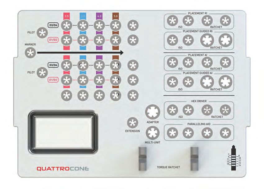
MULTI-UNIT ABUTMENTS
                                       The final restoration is screwed onto the
                                       implants with the multi-unit abutments.
                                       The straight and 30 degree-angled multi-
                                       unit abutments allow optimal distribution
                                       of force on the bone.

                                                         QUATTROCONE30 IMPLANT CONNECTION
                                                         The implant connection has been developed specifically for
                                                         angled insertion. Its very deep conical force-locking and in-
                                                         terlocking tapered connection widely distributes the applied
                                                         forces into the implant. The finite element analyses per-
                                                         formed with the QUATTROCONE30 show a very uniform and
                                                         completely uncritical distribution of the von Mises stresses in
                                                         the implant shoulder region with a loading of 250 N.
                                                         The special QUATTROCONE30 implant connection efficiently
                                                         prevents the stress peaks that would otherwise arise under
                                                         these conditions. This in turn protects the surrounding bone
                                                         in this particularly sensitive region.

                                                                               CONVENTIONAL
                                                                               IMPLANT CONNECTION
                                                                               Conventional implant interface connections
                                                                               have partially high stress peaks in the implant
                                                                               shoulder region when an implant is inserted at
                                                                               an angle of 30°.
                                                                               These can have a detrimental effect on the
                                                                               surrounding bone.

QUATTROCONE30 THREAD DESIGN
The uniquely shaped and patented design of the                  As the flanks of the macrothread are angled at 30°, inserted
QUATTROCONE30 implants has been specially developed             at an angle, these implants behave like a conventional im-
for inclined implant insertion and thus bone preservation.      plant when an axial load is introduced – ideal! Both tipping
Cases in which QuattroFix* is indicated have their own spe-     movements of the implant and excessive stress in the criti-
cial requirements. This is the first solution to proficiently   cal crestal bone region are eliminated. This ensures reliable
address these requirements both scientifically and techni-      implant placement with lasting stability.
cally.

* QuattroFix is a special treatment concept for fixed, full-arch restoration for edentulous patients with an atro-               9
  phic alveolar ridge on two straight and two 30 degree-angled implants.
Implant diameters and lengths

                                                                             D 3.5            D 3.8             D 4.3            D 5.0

                                                                                Clear color coding of the implant diameters

                                                                                The visible indication of the implant diameter,
                                                                                framed by the color coding, makes it easier to visu-
                                                                                ally differentiate the respective implant diameters.
                                                                                The drill parts for the implant bed preparation are
                                                                                also highlighted with these colors.

                                    LENGTH
                                   DIAMETER            L 7.0                   L 9.0          L 11.0          L 13.0          L 15.0

                                       D 3.5

                                                                             3-01-02         3-01-03          3-01-04         3-01-05

                                       D 3.8

                                                      3-01-16                 3-01-17         3-01-18         3-01-19         3-01-20
     QUATTROCONE     RI*
                                       D 4.3

                                                     3-01-06                 3-01-07         3-01-08          3-01-09         3-01-10

                                       D 5.0

                                                      3-01-11                 3-01-12         3-01-13         3-01-14         3-01-15

                                       D 4.3

                                                                             4-01-01         4-01-02          4-01-03         4-01-04
     QUATTROCONE30   AI*
                                       D 5.0

                                                                             4-01-06         4-01-07         4-01-08          4-01-09

                           * Implant connection RI   Implant connection AI
                             (Regular interface)     (Angulated interface)
10
Implant connections
QUATTROCONE implant
RI AI
QUATTROCONE30 implant
RI D 3.5 mm – 5.0 mm AI D 4.3 mm – 5.0 mm
There is only one conical implant
Please note that it is essential that
connection size between the im-
plant and the abutment in the case the QUATTROCONE30 implant with
of implants with a diameter of 3.5 mm a diameter of 4.3 mm - 5.0 mm is only
- 5.0 mm, which is marked with RI (Reg- used with parts labeled with the implant
ular Interface). This means that all the Implant connection AI (Angulated Interface).
pick-ups, gingiva formers and abutments fit into
each of these implants. This markedly reduces
the number of components required and thus
achieves maximum transparency and efficiency.
Continuity of emergence profile
The shape (emergence profile) of the gingiva former and the temporary abutment exactly follows the shape
of the prosthetic abutment. Optional individual implant pick-ups are available to better transfer the selected
emergence profile to the model. These are also based exactly on the emergence profile of the gingiva former
and abutment.
RI D 3.5 - 5.0
Implants Gingiva former Temporary
Gingiva former
/Temporary resto-
ration
Ø 4.5 Ø 5.5 Ø 6.5 Ø 5.5
GH 1-6 GH 1-6 GH 1-6 GH 1-6
Implant pick-up
Ø 4.5 Ø 5.5 Ø 6.5 Ø 5.5
Emergence profile GH 1-2 GH 1-2 GH 1-2 GH 1-2
for
Implant pick-up
Ø 4.5 Ø 5.5 Ø 6.5 Ø 5.5
GH 3-6 GH 3-6 GH 3-6 GH 3-6
Abutment
Ø 4.5 Ø 5.5 Ø 6.5 Ø 5.5
GH 1.5-5 GH 1.5-5 GH 1.5-5 GH 1.5-5
11Drill
The three cutting edges of the step drill are designed to match the outer geometry of the implant. QUATTROCONE
implants can be positioned with two drilling steps. If diameters are larger, incremental drilling is recommended.
Different step drills for D1/D2 bones and D3/D4 bones.
Bright depth markings ensure optimum visibility.
Long service lives due to black surface coating.
Clear color coding and only 4 drills in total greatly simplify the protocol.
The QUATTROCONE standard and cortical drills are generally step drills, whose steps match the apical shape of the
implant, depending on the respective implant diameter.
MARKER DRILL ROUND DRILL NEEDLE DRILL
The marker drill is used to punch mark the bone
before the first deep drilling step. Two variants are
available. The first is the round drill (0-14-75) and the
second is the needle drill (0-14-77). This can be used
to guide the drilling process for instance, if the bone
is tapered or for drilling in extraction sockets. The
needle drill also features depth markings of 6 mm to 10
10 mm for depth measurement. 8
7
6
0
DRILL TYPES
Depending on the implant diameter and bone quality, up to five different drill types are available for the gentle
preparation of the bony implant bed. The color coding makes choosing the right drill extremely easy.
THE PILOT DRILL THE STANDARD DRILL
is marked with a gray ring and is used is used for the final depth drilling of the corresponding implant
as the first depth drill and axis align- diameter for D3/D4 bone quality. It is also used for incremental
ment for any implant diameter. drilling for large implant diameters. Its implant diameter can be
identified by its color ring.
If using the standard drill for the final deep drilling, the following
always applies: Implant diameter minus 0.3 mm (e.g. D 3.5 mm =
3.2 mm final drill hole)
THE CORTICAL DRILL
A detailed drilling is used for the final depth drill for D1/D2 bone quality in addition to the stan-
protocol is available on dard drill. Alongside the color coding for the implant diameter it also has a red
page 34 ring
If using the cortical drill for the final deep drilling, the following always
applies: Implant diameter minus 0.2 mm (e.g. for implant D 3.5 mm = 3.3 mm
final drill hole).
Especially suitable for D1/D2 bone quality in the lower jaw.
Here, if necessary, at full depth.
12THREE DRILL LENGTHS
There are three drill lengths available for each implant diameter which can be differentiated based on the narrow, silver
marking rings. The choice of drill length is only determined by the space available in the mouth. The depth marking on
the cutting surfaces is identical for all three drill lengths.
The drill lengths must, however, be taken into consideration when using and selecting the appropriate drill stops.
Detailed information is available under „Drill stops and combination tables“ on page 16.
Extra short drill Short drill Long drill
No narrow 1 narrow 2 narrow
silver marking ring silver marking ring silver marking rings
Full length 40.2 mm
Full length 31 mm
Full length 35.2 mm
25 mm
16 mm 20 mm
0.2 mm 0.2 mm 0.2 mm
The MedentiGuide System supports all drill lengths.* In the planning phase it is
important to ensure that the correct drill length is selected.
DEPTH MARKING
The depth markings on the cutting edges of the drill are graduated according to the available QUATTROCONE
and QUATTROCONE30 implant lengths.
PLEASE NOTE:
The stated drill depths
15 do not include the 0.2 mm
13
11 tip of the drill bit. Please
9
8
observe their length if there
7 is not much space available
for anatomic structures. Please
0 consult the table for the drill tip
0.2 lengths.
Pilot drill
Standard drill
Cortical drill
The QUATTROCONE standard and cortical drills are generally step drills whose steps match the apical shape of
the implant, depending on the respective implant diameter.
13
* depending on the planning software used.DEPTH MARKING
QUATTROCONE QUATTROCONE30
9 mm 11 mm 13 mm 15 mm
15 mm 13 mm 11 mm 9 mm 7 mm 30° 30° 30° 30°
16
15
14
13
12
11
9
10
8
7
0.2
QUATTROCONE30
Implant
length
L 9.0
QUATTROCONE30 LENGTH SPECIFICATIONS
The implant length is the distance between the implant tip and
shoulder in the central axis region.
8
10
14Conventional treatment planning
Treatment planning must take generally applicable and implantology must be taken into account.
guidelines for implant prosthetics into account, along In the preprosthetic planning, the best possible
with surgical perspectives such as general patient placement of the implants should be planned in
history, contraindications, intraoral findings and risk consultation with the prosthodontist with esthetics and
factors. function in mind.
Once the findings have been evaluated, treatment can In the surgical planning it is important to carefully
be planned based on the following considerations: assess if there is sufficient bone available to ensure
primary stability of the implants.
• Preprosthetic planning
• Surgical planning
The indications and contraindications for dental surgery
SURGICAL PLANNING PREPROSTHETIC PLANNING
In the preoperative planning it is important to carefully Preprosthetic planning and thus the best possible,
assess whether the jaw bone is sufficiently wide and high to tooth-analog positioning of the implants is the
hold implants. Vestibular and oral lamella should be at least most important prerequisite for ensuring the im-
1.5 mm wide after implant insertion. Determine the position plantation is a sound foundation for an esthetic
and orientation of important anatomical structures such and functional prosthetic.
as the mental foramen or sinus cavity radiographically. If
augmentation is required, these regions must demonstrate
complete and mechanically stable regeneration before
preparation. Implant lengths and diameters are selected by
placing the X-ray template on the OPG (note the magnifica-
tion scale). A subscrestal positioning of the implant must be
taken into account in the X-ray analysis.
15Drill stops and combination tables
The QUATTROCONE drill stop ensures precise control of the drilling depth during implant bed preparation for
placing QUATTROCONE implants. The advantage of this drill stop is that it can be used for both simple and more
complex cases where the position of the mandibular nerve or sinus floor is relevant. The drill stops are supplied
nonsterile and should be sterilised prior to use. The drill stops may be used only with the QUATTROCONE drills.
The drill stops are available for all implant diameters and lengths.
PLEASE NOTE:
QUATTROCONE drill stops are not indicated for:
1. Extraction sockets, in which the bone cavity is much wider than the required support diameter for the drill stop.
2. Use as guide sleeves in drill templates.
Extra-short drill (16 mm)
Implant length
Implant diameter/drill type
L 7.0 L 9.0 L 11.0 L 13.0 L 15.0
QUATTROCONE
All implant diameters 6 4 2
Pilot drill Ø2.0mm (4-14-16) (4-14-14) (4-14-12)
D 3.5 20 18 16
Standard/Cortical (4-14-30) (4-14-28) (4-14-26)
D 3.8 59 58 57
Standard/Cortical (4-14-77) (4-14-76) (4-14-75)
D 4.3 34 32 30
Standard/Cortical (4-14-44) (4-14-42) (4-14-40)
D 5.0 48 46 44
Standard/Cortical (4-14-62) (4-14-60) (4-14-58)
QUATTROCONE30
All implant diameters 3 1
Pilot drill Ø2.0mm (4-14-13) (4-14-11)
D 4.3 31 29
Standard/Cortical (4-14-41) (4-14-39)
D 5.0 45 43
Standard/Cortical (4-14-59) (4-14-57)
Drill stop number
16Short drill (20 mm)
Implant length
Implant diameter/drill type
L 7.0 L 9.0 L 11.0 L 13.0 L 15.0
QUATTROCONE
All implant diameters 10 8 6 4 2
Pilot drill Ø2.0mm (4-14-20) (4-14-18) (4-14-16) (4-14-14) (4-14-12)
D 3.5 24 22 20 18 16
Standard/Cortical (4-14-34) (4-14-32) (4-14-30) (4-14-28) (4-14-26)
D 3.8 63 61 59 58 57
Standard/Cortical (4-14-81) (4-14-79) (4-14-77) (4-14-76) (4-14-75)
D 4.3 38 36 34 32 30
Standard/Cortical (4-14-48) (4-14-46) (4-14-44) (4-14-42) (4-14-40)
D 5.0 52 50 48 46 44
Standard/Cortical (4-14-66) (4-14-64) (4-14-62) (4-14-60) (4-14-58)
QUATTROCONE30
All implant diameters 7 5 3 1
Pilot drill Ø2.0mm (4-14-14) (4-14-15) (4-14-13) (4-14-11)
D 4.3 35 33 31 29
Standard/Cortical (4-14-45) (4-14-43) (4-14-41) (4-14-39)
D 5.0 49 47 45 43
Standard/Cortical (4-14-63) (4-14-61) (4-14-59) (4-14-57)
Drill stop number
Long drill (25 mm)
Implant length
Implant diameter/drill type
L 7.0 L 9.0 L 11.0 L 13.0 L 15.0
QUATTROCONE
All implant diameters 14 13 11 9 7
Pilot drill Ø2.0mm (4-14-24) (4-14-23) (4-14-21) (4-14-19) (4-14-17)
D 3.5 28 27 25 23 21
Standard/Cortical (4-14-38) (4-14-37) (4-14-35) (4-14-33) (4-14-31)
D 3.8 66 65 64 62 60
Standard/Cortical (4-14-84) (4-14-83) (4-14-82) (4-14-80) (4-14-78)
D 4.3 42 41 39 37 35
Standard/Cortical (4-14-52) (4-14-51) (4-14-49) (4-14-47) (4-14-45)
D 5.0 56 55 53 51 49
Standard/Cortical (4-14-70) (4-14-69) (4-14-67) (4-14-65) (4-14-63)
QUATTROCONE30
All implant diameters 12 10 8 6
Pilot drill Ø2.0mm (4-14-22) (4-14-20) (4-14-18) (4-14-16)
D 4.3 40 38 36 34
Standard/Cortical (4-14-50) (4-14-48) (4-14-46) (4-14-44)
D 5.0 54 52 50 48
Standard/Cortical (4-14-68) (4-14-66) (4-14-64) (4-14-62)
Drill stop number
17Computer-aided treatment planning
with MedentiGuide
MedentiGuide
MedentiGuide drill sleeves support the surgeon in preparing the
implant bed for Medentika® implants. Their use must be planned
with a specially designed 3D planning system and surgical drill-
ing template. You can plan the surgery with standard planning
programs.
Treatment planning based on three dimensional imaging proce-
dures (CT, DVT) enables high precision treatment planning with
predictable outcomes.
The advantages over conventional planning include:
• Precision three-dimensional planning and implantation, taking
into account the desired restoration
• Automatic collision control that displays if the distances to the
implants or nerves are too short
• Information on peri-implant bone quality so that conclusions
can be drawn on the expected primary stability
An individual drilling template can be produced on the basis of the
digital planning data. This ensures the exact and precise transfer of
the planning outcome to the patient’s mouth.
18These software manufacturers* currently support the
MedentiGuide System
Note:
Medentika® GmbH accepts no liability for the correct planning, implementation and production of the drilling
template. Sufficient knowledge of the 3D planning system being used and the Medentika® implant system is
essential. It is imperative that the user is very confident in the use of 3D planning systems before using the
MedentiGuide drill sleeves. Furthermore, sufficient expertise in preoperative implant planning and dental im-
plantology is required.
* to some extent this depends on the availability of the updates of the specific manufacturer.
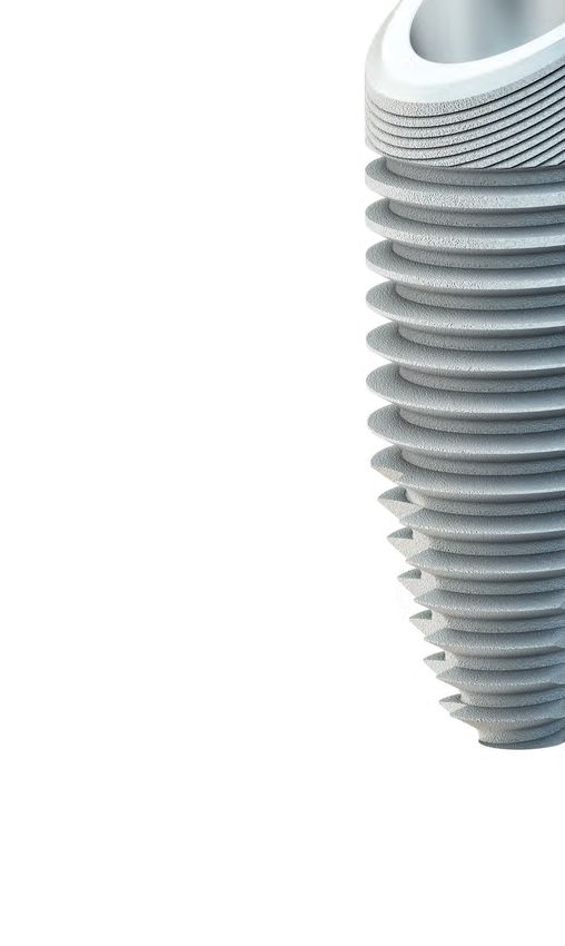
19Surgical tray
1
No gap between the tray and silicone
Tray Silicone Tray
2
The benefits
1 Superior hygiene capability with intelligently designed
silicone holders
2 Smooth, even surfaces accelerate and facilitate cleaning
3 Space for another drill set
4 9 additional slots
5 Removable metal dish for small parts
204
3
5
21Surgical tray layout diagram
The surgical tray is available with four layout options:
• As tray without contents
• Prefilled with the most important extra short design instruments
• Prefilled with the most important short design instruments
• Prefilled with the most important long design instruments
The exact layout of the surgical washing tray is shown in the item list of the corresponding variant.
There is space for two drill sets and the associated placement instruments and free slots for additional
instruments.
Removable stain-
less steel dish for
Extension Adapter Placement instru-
small parts
ISO shaft ISO shaft ment Torque ratchet surgical
0-13-55 0-13-50 Multi-unit 6-13-05
0-13-76
Depth gauge gingival height Depth gauge drill hole
0-13-17 0-13-75
Located in the floor of the surgery tray
22Bone
Marker Pilot D3.5 D3.8 D4.3 D5.0
quality
D3/D4
e-s: 4-14-86 e-s: 4-14-92 e-s: 4-14-88 e-s: 4-14-90
s: 4-14-02 s: 4-14-71 s: 4-14-04 s: 4-14-53
l: 4-14-07 l: 4-14-73 l: 4-14-09 l: 4-14-55
e-s: 4-14-85
Needle drill Round drill
s: 4-14-01
0-14-77 0-14-75
l: 4-14-06
D1/D2
e-s: 4-14-87 e-s: 4-14-93 e-s: 4-14-89 e-s: 4-14-91
s: 4-14-03 s: 4-14-72 s: 4-14-05 s: 4-14-54
l: 4-14-08 l: 4-14-74 l: 4-14-10 l: 4-14-56
e-s = extra-short; s = short; l = long
Placement instrument implant RI
Contra-angle Manual and ratchet
extra-short 2-13-32 extra-short 2-13-35
short 2-13-33 short 2-13-36
long 2-13-34 long 2-13-37
Placement instrument MedentiGuide RI
Manual and
Contra-angle
ratchet
extra-short 3-32-11 extra-short 3-32-12
short 3-32-07 short 3-32-09
long 3-32-08 long 3-32-10
Placement instrument implant AI
Contra-angle Manual and ratchet
extra-short 4-13-08 extra-short 4-13-11
short 4-13-09 short 4-13-12
long 4-13-10 long 4-13-13
Placement instrument MedentiGuide AI
Manual and
Contra-angle
ratchet
short: 4-32-07 short: 4-32-09
long: 4-32-08 long: 4-32-10
Placement instrument Hex 1.26
Contra-angle Manual and ratchet
extra-short 0-13-18 short 0-13-22
short 0-13-04 long 0-13-23
long 0-13-05
Paralleling aid Drill aid
Implant RI Drill QUATTROCONE 30
2-13-31 0-13-74 4-13-07
23Surgery washing tray
THE EFFICIENT CLEANING METHOD.
The new surgery washing tray has been designed for the surgical instruments to be prepared as easily and
efficiently as possible.
• The separate compartment with a silicone insert is
used to store additional instruments, such as the
torque ratchet surgical.
• The silicone insert prevents the instruments from
touching, thereby preventing contact corrosion and
ensuring thorough cleaning.
• The separate lid prevents small instruments from
falling out.
If you prefer to use sterile containers, the JN295 from
Aesculap®, for example, is a suitable option.
24• The surgery washing tray is made of corrosion-free medical
stainless steel.
• The height of the tray means that it easily holds even long drills
and instruments.
• It can hold two full drill sets and the matching MedentiGuide
placement instruments.
• The aluminum template printed with the layout diagram is
used to clearly arrange all instruments.
• The template is removable to optimize the instrument cleaning
process.
• The grid structure and the specially designed retaining sleeves
with point-by-point instrument holder ensure that all instru-
ments are well rinsed and thereby produces reproducible
cleaning results.
25Surgery washing tray layout diagram
The layout of the surgery washing tray is shown in the item list of the corresponding variant.
It can hold two drill lengths and the matching MedentiGuide placement instruments.
Ball Torx placement instrument
Optiloc placement instrument Manual and
Contra-angle
ratchet
Contra-angle Manual and ratchet
short 0-13-60 short 0-13-59
0-13-82 0-13-61 long 6-13-06
Torque ratchet surgical
6-13-05
Adapter
ISO shaft
Depth gauge Depth gauge 0-13-50
Gingival height Drill
0-13-17 0-13-75
Placement instrument MedentiGuide RI
Manual and
Contra-angle
ratchet
extra-short 3-32-11 extra-short 3-32-12 Paralleling aid
short 3-32-07 short 3-32-09 Drill
long 3-32-08 long 3-32-10
0-13-74
Placement instrument MedentiGuide AI
Drill aid Manual and
Contra-angle
QUATTROCONE 30 ratchet
4-13-07 short: 4-32-07 short: 4-32-09
long: 4-32-08 long: 4-32-10
26D 3.5 D 3.8 D 4.3 D 5.0
Placement instrument Hex 1.26 Color coding of the implant diameter
Manual and
Contra-angle
ratchet
extra-short 0-13-18 short 0-13-22
short 0-13-04 long 0-13-23
long 0-13-05
Ball Hex placement instrument
Contra-angle Manual and ratchet
0-13-39 0-13-38
Implant Standard drill Cortical drill
diameter
D5.0
Placement instru-
e-s: 4-14-90 e-s: 4-14-91
ment MedentiBase s: 4-14-53 s: 4-14-54
0-13-37 l: 4-14-55 l: 4-14-56
D4.3
e-s: 4-14-88 e-s: 4-14-89
Multi-unit place- s: 4-14-04 s: 4-14-05
ment instrument l: 4-14-09 l: 4-14-10
0-13-76
D3.8
e-s: 4-14-92 e-s: 4-14-93
s: 4-14-71 s: 4-14-72
l: 4-14-73 l: 4-14-74
Extension
ISO shaft D3.5
0-13-55 e-s: 4-14-86 e-s: 4-14-87
s: 4-14-02 s: 4-14-03
l: 4-14-07 l: 4-14-08
Pilot drill
e-s: 4-14-85
s: 4-14-01
l: 4-14-06
Placement instrument implant AI
Contra-angle Manual and ratchet
extra-short 4-13-08 extra-short 4-13-11 Marker
short 4-13-09 short 4-13-12
long 4-13-10 long 4-13-13 Needle drill Round drill
0-14-77 0-14-75
e-s = extra-short; s = short; l = long
Placement instrument implant RI Paralleling aid
Contra-angle Manual and ratchet Implant RI
extra-short 2-13-32 extra-short 2-13-35
short 2-13-33 short 2-13-36 2-13-31
long 2-13-34 long 2-13-37
27The new implant packaging
The new implant packaging for the QUATTROCONE system has been developed to make handling even
easier. The compact implant packaging makes storage more efficient. Important parameters, such as the
article number, diameter, length, implant connection and type can be clearly identified.
28• The double information label applied over the corner al-
lows flexible implant storage; important product informa-
tion is visible at a glance.
• Clear, compact information labels with the key data make
it easier to distinguish between the implants. The implant
diameters are visible at a glance by the color coding on the
information labels.
• Implants can be clearly identified
through the inspection window
• The perforation on the outer packaging made of
environmentally friendly cardboard makes it easy
to access the sterile packaging..
• The implant is supplied in a sterile container, pro-
tected by a blister with outer packaging. The blister
thereby acts as a sterile barrier.
29The new implant packaging
PATIENT LABEL
There are two peel-off labels on the blister package which can
simply be affixed in the implant pass for documentation.
SYMBOL DESCRIPTION AND IFU
Please refer to the IFU for further information - www.medentika.com/ifu
Lot number Use-by date
Article number Do not re-use
Manufacturer CE marking with the
identification number of the
Notified Body
Date of manufacture Caution
See Instructions for Use Medical device
Sterilization by radiation Store dry
MR Conditional Do not use if the packaging is
damaged
US Federal law restricts this device to sale by or on the order of a doctor.
30The new placement instrument
The new placement instrument is now even easier to use. Spring clips hold the implant on the placement instrument
when the implant is removed.
Each is available in three lengths with an ISO shaft and is designed for manual use or use with a ratchet.
TWO VARIANTS
• With ISO shaft for use in the handpiece.
• With a knurled handle for manual operation and insertion in the torque
ratchet surgical.
POSITION MARKINGS
for precise alignment of the square implant connection.
SPRING CLIPS
for excellent implant purchase.
We recommend using the new
placement instrument in combination
with the QUATTROCONE implant.
Torque ratchet surgical
The three-part stainless steel torque ratchet has been especially designed for surgical use. It is easy to handle and can be
sterilized assembled.
The torque scale is easy to read and extends from 0 to 45 Ncm.
31Implant removal
1 2 3
Take the blister out of the outer Remove the Tyvek film from the Push down the lid keeping the
packaging. blister pack to expose the contain- container upright.
er with the implant.
(Caution: This removes the sterile
barrier.)
4 5 6
>>SOFT-CLICKREMOVING THE CLOSURE SCREW
1 2 3
The included closure screw is on Use the HEX 1.26 placement Turn the closure screw hand tight
the underside of the container. instrument to remove the closure (5-10 Ncm).
Not with QUATTROCONE30 screw. Unscrew the closure screw
from the container.
33The drilling protocol
Marker with needle drill
Cortical drill for D1/D2
Incremental drilling
Implant diameter
bone quality
Final drilling
Pilot drill
D 3.5 3.2 mm* 3.3 mm*
D 3.8
3.5 mm* 3.6 mm*
1.6 mm 2.0 mm* D 4.3
4.0 mm* 4.1 mm*
D 5.0
4.0 mm* 4.7 mm* 4.8 mm*
*Drill diameter
The recommended drill speed is 300-600 rpm. The maximum speed of 800 rpm should not be exceeded.
Replace the drill bit after no more than 30 uses. Irrespective of this, the condition of the drill bit must be checked
before and after each use to ensure it is in perfect condition and replaced where necessary.
34IMPLANTATION STEP-BY-STEP
QUATTROCONE Example for QUATTROCONE D 4.3 x L 11.0
Implant bed preparation
First marker drill with the Pilot drill hole with the pilot
Incision phase needle drill Ø 1.6 mm drill Ø 2.0 mm
1 2 3
The incision phase serves to form a The marker drill is inserted following The pilot hole is drilled with the Ø
mucosa flap to reveal the implanta- the mobilization of the mucoperios- 2.0 mm pilot drill. This defines the
tion point as bone. teal flap with the needle drill and sagittal direction of the implant
This incision phase is case-depen- can also alternatively be performed axis and the drilling depth (observe
dent and must be considered based with the aid of a drilling template. depth marking).
on the patient’s individual require- A template-based implantation is
ments and the healing mode (sub- recommended for the definitive
merged or open healing). alignment and to prevent devia-
tions from the implant planning.
While drilling it is essential to ensure sufficient cooling, e.g. NaCl liquid, to avoid
overheating and thus damage to the bone.
Reaming with the standard Reaming with standard drill Reaming with the cortical drill
drill (pink) (purple) (purple/red)
Ø 2.0 / 3.2 (optional) Ø 2.0 / 3.2 / 4.0 mm Ø 2.5 / 4.0 / 4.1 mm
4 5a 5b
In this case, reaming is initially car- The final reaming is completed us- It is recommended in the event of
ried out with the standard drill Ø ing the standard drill Ø 2.0 / 3.2 / 4.0 an extremely compact cortex and
2.0 / 3.2 mm. The laser markings mm. an average spongiosa or D1/D2
that correspond to the respective bone quality in the lower jaw using
implant length serve to inspect the additionally the cortical drill with a
depths for their part. diameter of 2.5 / 4.0 / 4.1 mm.
35
Note: All components used in the patient’s mouth must be secured against aspiration and swallowing.IMPLANTATION STEP-BY-STEP
Implant insertion
Implant placement with the Final positioning with the Remove the placement instru-
contral angled handpiece torque ratchet surgical ment
1a 1b 2
If the implant is inserted with the If the implant is inserted with the Once the implant has reached its
placement instrument for the an- torque ratchet surgical and the final position, the placement instru-
geled handpiece, a max. number manual insertion instrument, the ment should be carefully removed
of 25 rpm and a torque of 35 Ncm torque should not exceed 35 Ncm. from the implant (either with the
should not be exceeded. However, if If the torque is insufficient, we rec- handpiece or the ratchet).
35 Ncm is not sufficient to reach the ommend carefully unscrewing the
final implant position, carefully un- implant and then widening the im-
screw the implant and enlarge the plant bed with the cortical drill (see
implant bed with the cortical drill implant bed preparation).
(see implant bed preparation).
Subcrestal implant position Paralleling aid
3 4
2 mm subcrestal
1 mm subcrestal
1 mm
Due to the internal tapered connection the implant can be inserted approx. The paralleling aid can be used for
1 mm subcrestally if there is a sufficient amount of bone in a vertical direc- orienting to the selected implant
tion, in order to stabilise the periimplant bone better. Such a procedure en- axis when inserting several im-
sures unencumbered healing even under the mucosa supported dentures plants.
and can improve the prosthetic results in esthetically relevant area if there This can be performed either by
is not enough soft tissue available. placing the paralleling aid in the im-
In the case of the pre-surgical planning and the observation of the laser plant bed or by placing the parallel-
marking of the bit you must ensure the subcrestal implant position has ing aid directly in the implant.
been planned in advance.
For depth control during subcrestal placement, laser markings are provided
on the insertion instrument.
36NOTE: The plugged connection between the implant and the
placement instrument means that it is not possible
during an open sinus lift operation, for example, to pull
the implant back if required, as this could release this
connection.
In unfavorable cases there is a risk that an implant could
be displaced in the maxillary sinus. Complex surgical
measures would then have to be taken to recover the
implant.
FURTHER TREATMENT
Option 1: Transgingival healing
Insertion of the gingiva former Wound closure
1 2
If the implant is intended for transgingival The wound edges adapted by sutures to the
healing, the gingiva former must be inserted gingival tension free but salavia close by su-
in accordance with the thickness of the soft tures.
tissue following the removal of the place-
ment instrument. PLEASE NOTE:
The diameter of the gingiva former must be If the patient has a temporary restoration
selected in accordance with the prosthetic with a partial or full prosthesis, ensure that
requirements. there is no contact with the gingiva former or
the temporary restoration.
37FURTHER TREATMENT
Option 2: Submerged healing
Inserting the closure screw Wound closure Incision
1 2 3
If the implant is intended for sub- The alveolar ridge is closed by su- Following the localization of the
merged healing, the closure screw tures to prevent ingress of saliva. implant and the point-based anes-
must be inserted hand tight with The suturing should ideally be free thetic directly above the implant a
the Hex 1.26 hand instrument fol- of tension. To document the final limited crestal cut is performed to
lowing the removal of the place- implant position, a post operation the implant surface.
ment instrument implant. X-ray could be done. A load-free
healing phase must be ensured.
Uncovering Removal of the closure screw Insertion of the gingiva former
4 5 6
The central interior hex of the clo- The closure screw must be removed In accordance with the prosthetic
sure screw is found with the probe. with the Hex 1.26 hand instrument. requirements, the gingiva former
Connective tissue or bone must be that fits must be screwed in with
removed with the sharp curette the Hex 1.26 hand instrument.
above the locking closer screw. If necessary, adapt the wound mar-
Bones which disrupt the emergence gins to the gingiva former and se-
profile must be removed. cure with sutures.
38FURTHER TREATMENT
Option 3:
Immediate restoration with a provisional
If the clinical conditions allow an immediate restoration, the patient could get immediately after insertion of the
implants an implant-supported denture by using the temporary abutment.
It must be pointed out, that the temporary restoration has to stand out of occlusion so the implant can heal
unloaded. The surgeon is responsible for explaining to the patient how load-free implant healing can be achieved
postoperatively.
Preparing the temporary restoration
The temporary restoration is manufactured on the temporary abutment.
The grinding operation should be performed outside of the mouth.
Temporary abutments with an emergence diameter of 5.5 mm, straight
and angled, are available to ensure easy individualization.
Furthermore, temporary abutments are available as a metal base, which
are used for additive procedures.
Insertion of the temporary restoration
Before inserting the temporary restoration, the interface of the implant
should be cleaned with an air/water spray. The abutment is then inserted
with a torque ratchet or a torque-controlled angled handpiece at 25 Ncm.
For cemented restorations the use of provisional cementum is
recommended. Remove all excess cement from the margin of the crown.
Ensure that the wound is closed to prevent ingress of saliva.
PLEASE NOTE:
Temporary restorations must be replaced after six months at the latest.
Loads
The precondition for immediate stressing is primary stability that is greater than or equal to 35 Ncm. The
possibility of excess stress through the temporary restoration should be ruled out. No occlusion or articulation
contacts may be present. An insertion torque of at least 35 Ncm during the initial healing phase reduces the risk
of macromovements at the implant bone boundary, for instance through tongue or cheek pressure.
Studies1, 2 demonstrate that micromovements up to a threshold value of approx. 150 μm are tolerated during the
osseointegration of dental implants.
Successful osseointegration can also take place in the event of “non-functional immediate stress” subject to the
precondition that this value is not exceeded and all the other requirements are fulfilled.
1
Brunski JB: Biomechanical factors affecting the bone-dental implant interface.
Clin Mater 1992; 10 (3): 153–201
2
Brunski JB: Avoid pitfalls overloading and micromotions of intraosseous implants.
Dent Implantol Update 1993; 4 (10): 77–81
39QUATTROCONE30 Example for QUATTROCONE30 D 4.3 x L 11.0
Implant bed preparation
The first drill hole for the straight implant is drilled into the upper or lower jaw with a pilot drill. Once the tip
of the drill aid is positioned in this drill hole, it can be aligned according to the clinical requirements. Once
secured, it is used as a drill guide. This ensures that drilling is exactly at an angle of 30°.
Drill aid QUATTROCONE30
This is used during implant preparation
based on the QuattroFix concept to
establish the exact angle for drilling. The
length of the drill aid is flexible and it can
be rotated in three axes.
Art. No. 4-13-07
While drilling it is essential to ensure sufficient cooling, e.g. NaCl liquid, to avoid
overheating and thus damage to the bone.
1 Implant bed preparation
Preparing the later implant bed for the
straight implant with the pilot drill.
Minimum drill depth 9 mm.
2 Inserting the drill aids
Insert the QUATTROCONE30 drill aid
and prepare the implant bed for the
QUATTROCONE30 implant with the pilot
drill to the required implant length.
403 Enlarging the implant bed
Enlarge the implant bed with the final drill
according to the implant diameter.
Implant insertion
1 Inserting the implant
The implant is inserted with the
placement instrument (manually with a
ratchet or the angled handpiece) without
exceeding the maximum torque of 35
Ncm. However, if this torque of 35 Ncm
has to be exceeded in order to achieve the
final implant position, carefully unscrew
the implant and enlarge the implant bed
with the cortical drill.
2 Paralleling aid
For the correct insertion of the
QUATTROCONE30 implant, you can use
the parallelization guide to check the
30° axis and the correct alignment of the
prosthetic axis on the alveolar ridge.
3 Enlarging the implant bed
After inserting the angled
QUATTROCONE30 implant, enlarge the
implant bed with the final drill based
on the implant diameter of the straight
QUATTROCONE implants.
41w 4 QuattroFix
Straight and angled implants
inserted in the correct ratio for the
QuattroFix treatment.
Inserting the abutment
1 Multi-unit abutment 30°
After inserting the implant, the
30° angled multi-unit abutment is
connected to the implant with the
special insertion aid.
Once the abutment is positioned, it
is tightened with the screw with a
maximum torque of 25 Ncm.
5 Straight multi-unit abutment
The straight multi-unit abutment is
screwed into the implant with the
placement instrument 0-13-76.
5 Final situation
Once the multi-unit abutment has been
positioned, the restoration treatment is
continued.
4243
QUATTROCONE    QUATTROCONE30

     Clinical examples of QuattroFix

                   Initial situation            3D planning

               Check the implant bed          Insert the implant

                    X-ray image             Position the abutment

           Situation after suture closure   Temporary restoration

44
QUATTROCONE QUATTROCONE30
Situation after healing time Milled zirconium bridge
Final restoration Final situation
Clinical case:
Dr. med. dent. Martin Müllauer
45Science
Func&onal
Func&onal
bone
bone
adapta&on
adapta&on
to
angulate
to
ang
Abboud
Abboud
M,
Rugova
M,
Rugov
SH,
Department
Department
of
Prosthodon0cs
of
Prosthod
Stony
BStony
rook
UBniversity,
rook
University,
School
Sochool
f
Den
Introduc&on
Introduc&on
Conven0onal
implants
placed
in
25-‐45
degree
angula0on
have
provided
a
Conven0onal
implants
placed
in
25-‐45
degree
angula0on
have
provided
a
significant
significant
alterna0ve
alterna0ve
for
the
for
restora0on
the
restora0on
of
maxillary
of
maxillary
and
mandibular
and
mandibular
posterior
posterior
segments
segments
in
order
in
to
order
overcome
to
overcome
anatomical
anatomical
constraints.
constraints.
Based
Based
on
the
on
available
the
available
clinical
clinical
studies,
studies,
the
0lted
the
implants
0lted
implants
are
not
are
subject
not
subject
to
a
to
a
Fig 3: Radiographs
Fig 3: Radiographs
after immediate
after immediate
implant placement
implant placement
in extraction
in e
higher
implant
failure
rate,
but
there
are
strong
indica0ons
from
in-‐vitro
higher
implant
failure
rate,
but
there
are
strong
indica0ons
from
in-‐vitro
and
in-‐vivo
studies
that
increased
stress
paKerns
and
0pping
of
the
0lted
and
in-‐vivo
studies
that
increased
stress
paKerns
and
0pping
of
the
0lted
implant
implant
during
dloading
uring
loading
nega0vely
nega0vely
affect
carestal
ffect
cbrestal
one
remodeling.
bone
remodeling.
This
can
This
can
lead
to
ongoing
crestal
bone
loss1
over
0me,
by
itself
increasing
the
risk
lead
to
ongoing
crestal
bone
loss1
over
0me,
by
itself
increasing
the
risk
for
peri-‐implant
for
peri-‐implant
diseases.
diseases.
Methods
Methods
Fig 4: Radiographs
Fig 4: Radiographs
3 months 3 after
months
placement
after placement
in dog 1. Due
in dog
to 1.
oveD
overload only localised
overload onlycrestal bone
localised loss bone
crestal resulted
lossatresulted
the surrounding
at the su
The
study
was
approved
by
Ethical
Commitee
of
Murcia
University,
Spain.
Six
adult
The
study
was
approved
by
Ethical
Commitee
of
Murcia
University,
Spain.
Six
adult
Fox
Hound
dogs
have
been
used
in
this
experiment.
All
3
mandibular
premolars
and
Fox
Hound
dogs
have
been
used
in
this
experiment.
All
3
mandibular
premolars
and
the
first
molar
of
each
dog
were
extracted
and
4
conven0onal
implants
(Meden0ka
the
first
molar
of
each
dog
were
extracted
and
4
conven0onal
implants
(Meden0ka
Implants
Implants
GmbH,
Huegelsheim;
GmbH,
Huegelsheim;
Germany)
Germany)
were
immediately
were
immediately
inserted
inserted
straight
straight
and
4
and
4
newly
designed
newly
designed
0lted
implant
0lted
implant
(QuaKrocone,
(QuaKrocone,
Meden0ka
Meden0ka
Implants
Implants
GmbH,
Germany)
GmbH,
Germany)
were
inserted
were
inserted
in
a
30
diegree
n
a
30
adngula0on.
egree
angula0on.
Fig 5: Radiographs
Fig 5: Radiographs
3 months 3after
months
placement
after placement
in dog in dog Fig
2. Crestal2.bone
Crestal
wasbone
maintaned
was maintaned
around thearound
straight
the straight with
and tilted implants.
and tilted implants. aro
Fig 1: All implants
Fig 1: Allare
implants
placedareusing
placed
a surgical
using aguide
surgical
(left).guide
The (left).
two newly
The two
designed
newly implants
designedare
implants
placedare
in aplaced
30 in a 30
Result
R
degree angledegree
to the
angle
distal
to the
(right).
distal (right).
In
the
first
group
the
immediate
loading
of
the
implants
was
performed
with
a
bar.
In
the
first
group
the
immediate
loading
of
the
implants
was
performed
with
a
bar.
The
radiographic
analysis
revealed
that
The
radiographic
analysis
reveale
In
the
second
In
the
second
group
the
group
implants
the
implants
were
inserted
were
inserted
in
the
extrac0on
in
the
extrac0on
sockets
sockets
without
without
occurred
occurred
following
following
implant
implant
installa0oninsta
loading
loading
and
aZer
and
3
aZer
months
3
months
of
healing
of
healing
the
implants
the
implants
were
loaded
were
with
loaded
a
bar
with
for
a
bar
for
another
another
3
months.
3
months.
Radiographs
Radiographs
were
obtained
were
obtained
from
all
from
implant
all
implant
sites
following
sites
following
pronounced
pronounced
at
implants
at
implants
without
withou
imm
implant
implant
installa0on,
installa0on,
and
aZer
and
3
aZer
and
6
3
months.
and
6
months.
The
animals
The
animals
were
sacrificed
were
sacrificed
and
and
altera0ons
altera0ons
that
were
that
were
observed
observed
at
im
biopsies
biopsies
from
all
firom
mplant
all
ismplant
ites
were
sites
obtained
were
obtained
and
prepared
and
prepared
for
histological
for
histological
analysis.
analysis.
func0onal
func0onal
load
were
load
small
were
and
small
did
and
not
d
groups.
groups.
The
histological
The
histological
analysis
analysis
revea
Contact
Contact
(BIC)
o(f
BIC)
63.48%
of
63.48%
with
values
with
vbalueetw
exposed
to
func0onal
load
exhibited
a
h
exposed
to
func0onal
load
exhibi
implants
implants
without
without
loading.
loading.
There
Twhere
as
no
w
regarding
regarding
the
newly
the
newly
designed
designed
0lted
0i
Fig
2:
The
straight
and
angulated
implants
are
placed
epicrestally
(leZ).
Implants
in
Group
1+2
are
connected
with
a
angula0on
Fig
2:
The
straight
and
angulated
implants
are
placed
epicrestally
(leZ).
Implants
in
Group
1+2
are
connected
with
a
angula0on
compared
compared
to
the
tco
onven0ona
the
conve
metal
bar
(SFI
metal
bar)
bar
and
(SFI
immediately
bar)
and
immediately
loaded
(right).
loaded
(right).
46The QUATTROCONE project is based on years of science and development of optimal implant
screw geometries for immediate loading and implant placement by Professor Dr. M. Abboud
(State University of New York Stony Brook, USA). Medentika® has integrated the patented
design components into a novel implant with a unique approach to the indications of angu-
lated insertion including QuattroFix.
gulated
ed
and
asnd
traight
straight
implant
implant
placement
placement
va
,
Calvo
SH,
CGalvo
uirado
Guirado
JL
JL
s
don0cs
and
Digital
and
TDechnology
igital
Technology
ntal
l
of
D
Mental
edicine,
Medicine,
Stony
BSrook,
tony
BNrook,
Y
NY
Conclusions
Conclusions
Based
Based
on
the
on
radiologic
the
radiologic
anaylsis
anaylsis
and
the
and
histology
the
histology
results
it
can
be
concluded
that
the
newly
designed
results
it
can
be
concluded
that
the
newly
designed
implants
implants
placed
placed
in
a
30
in
degree
a
30
degree
angula0on
angula0on
show
show
extraction
sockets and
sockets
immediate
and immediate
loading in loading
dog 1. in dog 1. similar
similar
cor0cal
cor0cal
bone
maintenance
bone
maintenance
with
immediate
with
immediate
placement
placement
and
immediate
and
immediate
loading
loading
compared
compared
to
to
conven0onal
conven0onal
implants
implants
placed
placed
straight.
straight.
It
is
It
is
suggested
suggested
that
func0onal
that
func0onal
load
at
load
implants
at
implants
may
may
enhance
osseointegra0on
and
result
in
a
higher
BIC
enhance
osseointegra0on
and
result
in
a
higher
BIC
and
improved
and
improved
marginal
marginal
bone
stability.
bone
stability.
It
should
It
should
be
be
erload
Due tothe
overload
metal the
bar metal
fractured.
bar fractured.
Even with Even
this excessive expected
with this excessive expected
that
implants
that
implants
placed
placed
without
without
func0onal
func0onal
gurrounding
implants. implants.
have
ahave
n
increased
an
increased
risk
of
rcisk
restal
of
cb
restal
one
rbesorp0on.
one
resorp0on.
Fig 7: Patented
Fig 7: macrothread design parallel
Patented macrothread design to parallel
the implant shoulder
to the implant prevent
shouldertilting and tilting
prevent successfully maintain the
and successfully crestalthe
maintain bone
crestal bone
level. level.
g 6: Radiographs 3 months 3after
Fig 6: Radiographs placement
months in dog 3 in dog 3
after placement
hout immediate loading. Crestal
without immediate loading.bone lossbone
Crestal occurred
loss occurred
ound all around
of these
allimplants.
of these implants.
Results
ts
t
the
largest
amount
of
bone
loss
ed
that
the
largest
amount
of
bone
loss
n
and
that
alla0on
and
this
that
loss
this
was
loss
more
was
more
mediate
ut
immediate
loading.
The
bone
loading.
level
level
The
bone
mplants
exposed
at
implants
to
3
months
exposed
of
of
to
3
months
t
differ
did
significantly
not
differ
between
significantly
the
the
between
aled
s
an
average
revealed
Bone-‐to-‐Implant
an
average
Bone-‐to-‐Implant
ween
43.39%
es
between
to
92.05%.
43.39%
Implants
to
92.05%.
Implants
Fig
8:
Histology
Fig
8o:
f
Htistology
he
convn0onal
of
the
convn0onal
implant
(right)
implant
showed
(right)
similar
showed
results
similar
to
the
results
newly
to
dtesigned
he
newly
0lted
designed
implants
0lted
(leZ).
implants
(leZ).
higher
degree
of
BIC
than
control
The
smaller
ited
a
higher
degree
of
BIC
than
control
The
smaller
macro-‐thread
macro-‐thread
pitch,
pitch,
the
tapered
the
tapered
implant
implant
body
body
design
design
for
for
significant
was
difference
no
significant
in
bone
difference
in
lb one
increased
oss
loss
increased
primary
primary
stability,
stability,
the
self-‐cucng
the
self-‐cucng
macro-‐and
macro-‐and
the
ideal
the
ideal
force
force
implants
0lted
placed
placed
implants
in
a
30
degree
in
a
distribu0on
30
degree
distribu0on
of
the
of
macro-‐threads
the
macro-‐threads
make
make
the
newly
the
newly
designed
designed
implant
implant
an
an
al
implants
en0onal
placed
pslaced
implants
traight.
straight.
op0mal
op0mal
device
dfevice
or
the
for
angulated
the
angulated
inser0on
inser0on
and
the
and
All-‐on-‐4
the
All-‐on-‐4
©
concept.
©
concept.
Acknowledgement:
Acknowledgement:
Special
Special
thanks
to
Mteden0ka
hanks
to
M eden0ka
Implant
Implant
GmbH,
GmbH,
Germany
Germany
for
for
the
poroduc0on
the
produc0on
of
the
f
the
implants
implants
and
and
drill
bits
drill
bits
All-On-4® is a registered trademark of Nobel Biocare service AG
47You can also read