Osteotomy Plates 4.5 Surgical Technique - Locking Compression Technology by aap - aap Implantate AG
←
→
Page content transcription
If your browser does not render page correctly, please read the page content below
Osteotomy Plates 4.5
   Surgical Technique

Locking Compression Technology by aap
Disclaimer

This surgical technique is exclusively intended for medical professionals, especially physicians, and the-
refore may not be regarded as a source of information for non-medical persons. The description of this
surgical technique does not constitute medical advice or medical recommendations nor does it convey
any diagnostic or therapeutic information on individual cases. Therefore, the attending physician is
fully responsible for providing medical advice to the patient and obtaining the informed consent of the
patient which this surgical technique does not supersede.
The description of this surgical technique has been compiled by medical experts and trained staff of
aap mplantate AG with utmost diligence and to the best of their knowledge. However, aap Implantate
AG excludes any liability for the completeness, accuracy, currentness, and quality of the information
as well as for material or immaterial damages arising from the use of this information.
Content
Introduction . . . . . . . . . . . . . . . . . . . . . . . . . . . . . . . . . . . . . . . . . . . . . . . . . . . . . . . . . . . . . . . . . . . . . . . . . . . . . . . . . . . . . . . . . . . . . . . . . . . . . . . . .2
• Material . . . . . . . . . . . . . . . . . . . . . . . . . . . . . . . . . . . . . . . . . . . . . . . . . . . . . . . . . . . . . . . . . . . . . . . . . . . . . . . . . . . . . . . . . . . . . . . . . . . . . . . . . . . . . . . .2
• Processing (Sterilization & Cleaning) . . . . . . . . . . . . . . . . . . . . . . . . . . . . . . . . . . . . . . . . . . . . . . . . . . . . . . . . . . . . . . . . . . . . . . . . . . .2
• Intended Use . . . . . . . . . . . . . . . . . . . . . . . . . . . . . . . . . . . . . . . . . . . . . . . . . . . . . . . . . . . . . . . . . . . . . . . . . . . . . . . . . . . . . . . . . . . . . . . . . . . . . . . . . .2
• Indications/Contraindications . . . . . . . . . . . . . . . . . . . . . . . . . . . . . . . . . . . . . . . . . . . . . . . . . . . . . . . . . . . . . . . . . . . . . . . . . . . . . . . . . . .3
• Features & Benefits . . . . . . . . . . . . . . . . . . . . . . . . . . . . . . . . . . . . . . . . . . . . . . . . . . . . . . . . . . . . . . . . . . . . . . . . . . . . . . . . . . . . . . . . . . . . . . . . .4
Surgical Technique High Tiba Osteotomy Plate 4.5 .......................................... 6
• Preoperative planning . . . . . . . . . . . . . . . . . . . . . . . . . . . . . . . . . . . . . . . . . . . . . . . . . . . . . . . . . . . . . . . . . . . . . . . . . . . . . . . . . . . . . . . . . . . . . .6
• Patient positioning . . . . . . . . . . . . . . . . . . . . . . . . . . . . . . . . . . . . . . . . . . . . . . . . . . . . . . . . . . . . . . . . . . . . . . . . . . . . . . . . . . . . . . . . . . . . . . . . . .7
• Approach . . . . . . . . . . . . . . . . . . . . . . . . . . . . . . . . . . . . . . . . . . . . . . . . . . . . . . . . . . . . . . . . . . . . . . . . . . . . . . . . . . . . . . . . . . . . . . . . . . . . . . . . . . . . . . .8
• Preparing the plate . . . . . . . . . . . . . . . . . . . . . . . . . . . . . . . . . . . . . . . . . . . . . . . . . . . . . . . . . . . . . . . . . . . . . . . . . . . . . . . . . . . . . . . . . . . . . . . . . .8
• Placing K-wires . . . . . . . . . . . . . . . . . . . . . . . . . . . . . . . . . . . . . . . . . . . . . . . . . . . . . . . . . . . . . . . . . . . . . . . . . . . . . . . . . . . . . . . . . . . . . . . . . . . . . . .9
• Osteotomy . . . . . . . . . . . . . . . . . . . . . . . . . . . . . . . . . . . . . . . . . . . . . . . . . . . . . . . . . . . . . . . . . . . . . . . . . . . . . . . . . . . . . . . . . . . . . . . . . . . . . . . . . . .10
• Opening the osteotomy gap using a Lambotte chisel . . . . . . . . . . . . . . . . . . . . . . . . . . . . . . . . . . . . . . . . . . . . . . . . . . . . .11
• Checking, measuring and stabilizing the osteotomy gap . . . . . . . . . . . . . . . . . . . . . . . . . . . . . . . . . . . . . . . . . . . . . . . .12
• Inserting the LOQTEQ® High Tibia Osteotomy Plate . . . . . . . . . . . . . . . . . . . . . . . . . . . . . . . . . . . . . . . . . . . . . . . . . . . . . . .13
• Proximal plate fixation . . . . . . . . . . . . . . . . . . . . . . . . . . . . . . . . . . . . . . . . . . . . . . . . . . . . . . . . . . . . . . . . . . . . . . . . . . . . . . . . . . . . . . . . . . .14
• Compressing the lateral cortical bone (optional) . . . . . . . . . . . . . . . . . . . . . . . . . . . . . . . . . . . . . . . . . . . . . . . . . . . . . . . . . .16
• Distal plate fixation . . . . . . . . . . . . . . . . . . . . . . . . . . . . . . . . . . . . . . . . . . . . . . . . . . . . . . . . . . . . . . . . . . . . . . . . . . . . . . . . . . . . . . . . . . . . . . .17
• Replacing the spacers and securing the remaining plate holes . . . . . . . . . . . . . . . . . . . . . . . . . . . . . . . . . . . . . . . .18
• Replacing the standard screw by a locking cortical screw . . . . . . . . . . . . . . . . . . . . . . . . . . . . . . . . . . . . . . . . . . . . . .19
Surgical Technique Distal Femur Osteotomy Plate 4.5 ................................... 21
• Preoperative planning . . . . . . . . . . . . . . . . . . . . . . . . . . . . . . . . . . . . . . . . . . . . . . . . . . . . . . . . . . . . . . . . . . . . . . . . . . . . . . . . . . . . . . . . . . . . .21
• Patient positioning . . . . . . . . . . . . . . . . . . . . . . . . . . . . . . . . . . . . . . . . . . . . . . . . . . . . . . . . . . . . . . . . . . . . . . . . . . . . . . . . . . . . . . . . . . . . . . . .22
• Approach . . . . . . . . . . . . . . . . . . . . . . . . . . . . . . . . . . . . . . . . . . . . . . . . . . . . . . . . . . . . . . . . . . . . . . . . . . . . . . . . . . . . . . . . . . . . . . . . . . . . . . . . . . . . .22
• Preparing the plate . . . . . . . . . . . . . . . . . . . . . . . . . . . . . . . . . . . . . . . . . . . . . . . . . . . . . . . . . . . . . . . . . . . . . . . . . . . . . . . . . . . . . . . . . . . . . . . .23
• Placing K-wires . . . . . . . . . . . . . . . . . . . . . . . . . . . . . . . . . . . . . . . . . . . . . . . . . . . . . . . . . . . . . . . . . . . . . . . . . . . . . . . . . . . . . . . . . . . . . . . . . . . . .23
• Osteotomy . . . . . . . . . . . . . . . . . . . . . . . . . . . . . . . . . . . . . . . . . . . . . . . . . . . . . . . . . . . . . . . . . . . . . . . . . . . . . . . . . . . . . . . . . . . . . . . . . . . . . . . . . . .25
• Preparation of the angle gauge for closed-wedge osteotomy . . . . . . . . . . . . . . . . . . . . . . . . . . . . . . . . . . . . . . . . .25
• Inserting the LOQTEQ® Distal Femur Osteotomy Plate . . . . . . . . . . . . . . . . . . . . . . . . . . . . . . . . . . . . . . . . . . . . . . . . . . .29
• Distal plate fixation . . . . . . . . . . . . . . . . . . . . . . . . . . . . . . . . . . . . . . . . . . . . . . . . . . . . . . . . . . . . . . . . . . . . . . . . . . . . . . . . . . . . . . . . . . . . . . .30
• Compression of the osteotomy with a LOQTEQ® locking screw (red) . . . . . . . . . . . . . . . . . . . . . . . . . . . . . . . . .32
• Proximal plate fixation . . . . . . . . . . . . . . . . . . . . . . . . . . . . . . . . . . . . . . . . . . . . . . . . . . . . . . . . . . . . . . . . . . . . . . . . . . . . . . . . . . . . . . . . . . .34
Explantation . . . . . . . . . . . . . . . . . . . . . . . . . . . . . . . . . . . . . . . . . . . . . . . . . . . . . . . . . . . . . . . . . . . . . . . . . . . . . . . . . . . . . . . . . . . . . . . . . . . . . .36
Assembly instruction load drill guide .............................................................. 37
Implants . . . . . . . . . . . . . . . . . . . . . . . . . . . . . . . . . . . . . . . . . . . . . . . . . . . . . . . . . . . . . . . . . . . . . . . . . . . . . . . . . . . . . . . . . . . . . . . . . . . . . . . . . . . . .38
Instruments ....................................................................................................... 40
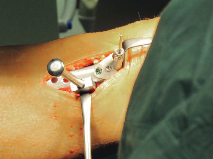
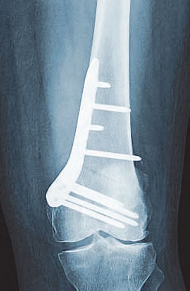
Case Studies ...................................................................................................... 43
aap Implantate AG Surgical Technique 1
Lorenzweg 5 • 12099 Berlin • Germany Osteotomy Plates 4.5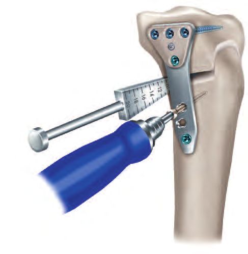
Introduction

    The LOQTEQ® Osteotomy System 4.5 is part of the LOQTEQ® portfolio and unifies angular stability with modern plate
    design for peri-knee osteotomies.

    The LOQTEQ® Osteotomy System 4.5 includes two plates:

    • The LOQTEQ® High Tibia Osteotomy Plate 4.5 (HTO) is designed for corrective osteotomy of the tibial head and is
      characteristic of joint-preserving corrections of tibial malalignment. Despite its short design, the LOQTEQ® High Tibia
      Osteotomy Plate 4.5 ensures stable fixation of open-wedge osteotomies and can therefore speed up postoperative
      mobilization through a smaller approach and excellent angular stability.

    • The LOQTEQ® Distal Femur Osteotomy Plate 4.5 (DFO) was developed for supracondylar femoral varus osteotomy and
      hence to correct the axis of the genu valgum in order to reduce the stress on the lateral joint compartment to counteract
      the progress of degenerative joint disease. The standard methods for corrective distal varus osteotomy are the lateral
      open-wedge technique or the medial closed-wedge technique. The method described here is state of the art and demonstrates
      the special features of the LOQTEQ® Distal Femur Osteotomy Plate 4.5 using the (femoral) closed-wedge method. The
      LOQTEQ® Distal Femur Osteotomy Plate 4.5 guarantees stable fixation of the correction. The unique feature of LOQTEQ®
      locking compression allows the plate to compress and maintain the required closed wedge osteotomy without any great
      effort.

    Material

    The LOQTEQ® implants and instruments are manufactured using high-quality materials, which have been proven to be
    successful in medical technology for decades. The anatomical plates and bone screws are made of titanium alloy.

    All materials employed comply with national and international standards. They are characterized by good biocompatibility,
    a high degree of safety against allergic reactions and good mechanical properties. LOQTEQ® implants feature an excellent,
    highly polished surface.

    Processing (Sterilization & Cleaning)

    The implants described in this surgical technique are supplied non-sterile.

    Implants and instruments that are supplied in non-sterile condition must be sterilized before use.
    For this purpose, please refer to the Instructions for Use that are enclosed with the plates, instruments and trays.

    Never use damaged implants or implants from damaged packaging.

    Intended Use

    The plate and screw implants of the system LOQTEQ® Osteotomy Plates 4.5 are intended for temporary fixation, correction
    or stabilization after osteotomy of the distal femur and the proximal tibia. Implants are intended for single use on human
    bone.

2    Surgical Technique                                                                        aap Implantate AG
     Osteotomy Plates 4.5                                                    Lorenzweg 5 • 12099 Berlin • Germany
Introduction

Indications / Contraindikations

Indications                                                               LOQTEQ® High Tibia LOQTEQ® Distal Femur
                                                                          Osteotomy Plate 4.5 Osteotomy Plate 4.5
Open-wedge osteotomies at the proximal medial tibia                                 √
Closed-wedge osteotomies of the medial distal femur                                                           √
Treatment of bone and joint deformities                                             √                         √
Treatment of malpositions caused by injuries or disorders such as
                                                                                    √                         √
osteoarthritis

Absolute contraindications
• Infection or inflammation (local or systemic)
• Allergies to the implant material
• Acute or chronic osteomyelitis at or close to the surgical field
• Unacceptably high anesthesia risk
• Severe soft tissue swelling compromising normal wound healing
• Insufficient soft tissue coverage
• Fractures in children and adolescents with epiphyseal plates that are not yet ossified
• Grade IV chondrosis of the medial compartment
• Total medial meniscectomy
• Gonarthrosis involving more than one compartment

Caution
aap products are not approved for the spine.

Relative contraindications
The circumstances listed below may negatively affect the success of surgery:
• Patient’s inability to cooperate in follow-up care (e.g. age-related impairments, dementia, alcoholism)
• Prior illnesses or comorbidities (e.g. osteoarthritis, osteoporosis, neurogenic or vascular diseases, diabetes mellitus,
   allergies, obesity)

Femur:
• Flexion less than 80 degrees
• Extension deficit above 20 degrees
• Symptomatic degenerative disorder of the patellofemoral joint
• Excessive lateral bone loss with valgus instability of the knee

                aap Implantate AG                                                                           Surgical Technique   3
                Lorenzweg 5 • 12099 Berlin • Germany                                                      Osteotomy Plates 4.5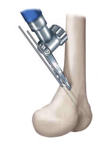
Introduction
                                                                    LOQTEQ® High Tibia Osteotomy Plate 4.5

    Features & Benefits

    • The anatomical plate design minimizes the need for intraoperative plate contouring

    • All plate holes are compatible with locking cortical screws

    • A fitted, radiolucent aiming device is designed for the safe placement of drill guides at a preset angle

    • A guide sleeve ensures right positioning of distal screws

    • Symmetrical plate in one length reduces the required storage capacities in the OR

           4.5 mm locking screws •
         allow the stable fixation
                      in the bone

                                                                    • Special spacers pro- •
                                                                     tect the pes anserinus

         High stability in the area •
         of critical load thanks to
        an evenly rounded transi-
          tion from head to shaft

             The tapered end of the •
            plate is designed for tis-
           sue-conserving, subcuta-
                      neous insertion

4    Surgical Technique                                                                       aap Implantate AG
     Osteotomy Plates 4.5                                                   Lorenzweg 5 • 12099 Berlin • Germany
Introduction
LOQTEQ® Distal Femur Osteotomy Plate 4.5

Features & Benefits

• The anatomical plate design minimizes the need for intraoperative plate contouring

• All plate holes are compatible with locking cortical screws

• Fitted, radiolucent aiming devices are designed for the safe placement of drill guides at a preset angle

• A guide sleeve ensures right positioning of distal screws

• Minor contact undercuts may help to preserve the blood supply to the periosteum

• Available as right and left version

         The tapered end of the •                               • Additional compression •
        plate is designed for tis-                                    can be achieved
      sue-conserving, sub-mus-                                     through the proximal
                   cular insertion                                   plate hole and by
                                                                   inserting an external
                                                                     compression and
                                                                   extension instrument.

      Gliding locking holes in •
   the shaft area allow com-
    pression and angular sta-
          bility with LOQTEQ®
                    technology

       4.5 mm locking screws •
     allow the stable fixation
                  in the bone

                aap Implantate AG                                                                       Surgical Technique   5
                Lorenzweg 5 • 12099 Berlin • Germany                                                  Osteotomy Plates 4.5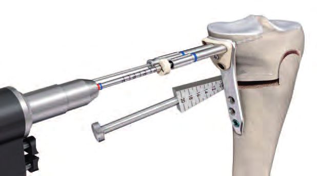
Surgical Technique
                                                                                    High Tibia Osteotomy Plate 4.5

    Preoperative planning

    • This surgical technique describes tibial head osteotomy using the example of the open-wedge method. Precise preoperative
      planning is essential for a successful procedure. This requires detailed knowledge of the anatomical and mechanical axes
      of the lower limb. For this purpose, take a weight-bearing X-ray of the entire leg in AP view and proceed as follows:

       A                                 A                               A
              Mikulicz line

                                                                                           α
                              Fujisawa
       C                      point
                                                         e

                                                       α

            B D                              B D

       1. Determine the mechanical leg axis (Mikulicz line). For this purpose, draw a straight line from the center of the femoral
          head (A) to the middle of the ankle joint (B).

       2. Determine the desired weight-bearing line. From the center of the femoral head (A), draw the line through the
          Fujisawa point (C), lateral to the preoperative center of the knee joint (60%), to the postoperative talocrural joint (D).

       3. Determine the center of rotation (e) laterally, in the proximal third of the tibiofibular joint but at least 15mm below
          the joint line.

       4. Connect the center of rotation with the preoperative endpoint (B) and the planned endpoint of the mechanical axis
          (D), and determine the resulting angle. This angle (α) should correspond to the open wedge osteotomy.

6    Surgical Technique                                                                          aap Implantate AG
     Osteotomy Plates 4.5                                                      Lorenzweg 5 • 12099 Berlin • Germany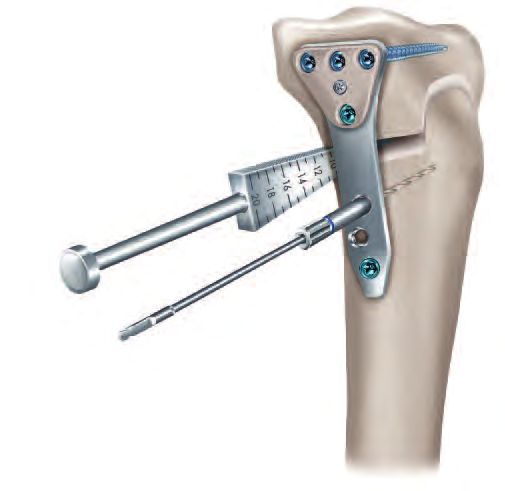
Surgical Technique
High Tibia Osteotomy Plate 4.5
• Conventional planning software can very clearly demonstrate the exact correction angles, incision depth of the osteotomy,
and the resulting height of the osteotomy.
• For the intraoperative control of the leg axis, the external alignment can be (optionally) used as well.
N OTE :
Planning software does not replace thorough planning and in-depth surgeon training on correcting axial
malalignments.
Patient positioning
• The patient is positioned supine on a radiolucent operating table. Ensure that the leg to receive surgery can be placed
in 90-degree flexion and complete extension.
• The surgery is performed in approx. 20° flexion to protect neurovascular structures. To facilitate the approach to the
medial aspect of the proximal tibia, extend the other leg and position it slightly lower. Intraoperatively, you must be
able to easily extend the leg to check the leg axis. A tourniquet may be placed.
N OTE :
Ensure that the head of femur and the ankle can be viewed under fluoroscopy.
aap Implantate AG Surgical Technique 7
Lorenzweg 5 • 12099 Berlin • Germany Osteotomy Plates 4.5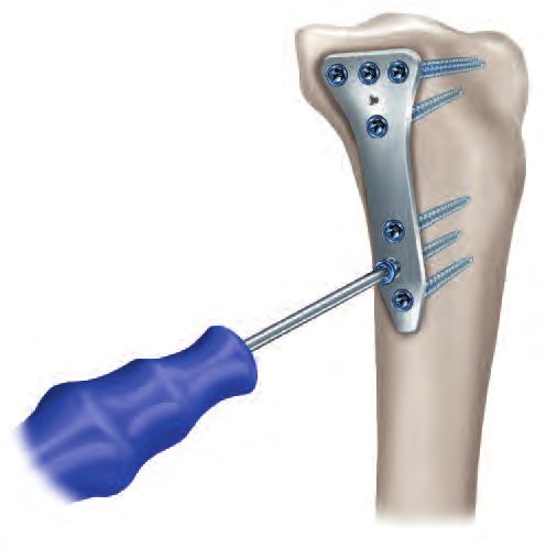
Surgical Technique
High Tibia Osteotomy Plate 4.5
Approach • Slightly bend the leg. Place the incision just below the tibial tuberosity
along the upper margin of the pes anserinus to the posteromedial edge
of the medial tibial plateau.
• For approach, perform the following steps:
1. Exposure of the pes anserinus and the superficial portion of the
medial collateral ligament.
2. Mobilization of the medial collateral ligament and release of the
superficial part using a raspatory.
3. Insertion of a soft tissue retractor between the medial collateral
ligament and tibia.
4. Detachment of the periosteum along the planned osteotomy.
Preparing the plate INSTRUMENTS ART.-NO.
Angle stable locking spacer LOQTEQ® 4.5 IU 7972-00
Aiming device LOQTEQ® HTO plate IU 8184-01
Screwdriver Duo, T25, quick coupling IU 7835-56
Fixing screw aiming device LOQTEQ® LFI T25 IU 8176-04
Large handle, cannulated, quick coupling IU 7706-00
• Screw the angle stable spacers (green) into the respective holes
manually.
• The spacers (green) are intended to prevent irritation of the pes
anserinus.
• Manually install the targeting device on the plate using the fixing
screw. This allows the correct screw connection of the drill guides
and the later use of the guide sleeve.
N OTE :
The fixing screw is connected to the aiming device in such a way
that it is self-retaining. It can be removed for cleaning by applying
gentle pressure to the tip of the screw from below.
8 Surgical Technique aap Implantate AG
Osteotomy Plates 4.5 Lorenzweg 5 • 12099 Berlin • GermanySurgical Technique
High Tibia Osteotomy Plate 4.5
Placing K-wires INSTRUMENTS ART.-NO.
K-wire with trocar point, ø2.5, L 200 NK 0025-20
Parallel drill guide for K-wire, ø2.5, narrow, PEEK IU 8188-25
Parallel drill guide for K-wire, ø2.5, broad IU 8190-25
Measuring device for K-wire 2.5, L 200 IU 7925-20
• Place the knee in 20° flexion and adjust the fluoroscope in such a way
as to enable an AP view of the tibia.
• Start the osteotomy immediately above the pes anserinus. Ensure
that there is enough space to easily place all proximal screws and
that they do not project into the osteotomy gap.
• Under fluoroscopic monitoring, insert a K-wire ø2.5 into the head of
tibia in accordance with the planned osteotomy. For this purpose,
start over the pes anserinus, target the head of fibula, and insert to
the far cortex.
N OTE :
Under fluoroscopic monitoring, check the position of the K-wire.
If its positioning is not satisfactory, a second wire can be placed
directly next to it and compared with the first one under fluoros-
copic monitoring. Then remove the wrongly positioned K-wire.
• Insert the parallel drill guide over the K-wire to the bone and insert
a second K-wire along the planned osteotomy. Under fluoroscopy,
position the K-wires above one another.
N OTE :
The sagittal inclination of the osteotomy should be parallel the
tibial plateau.
• To determine the incision depth, measure the depth of the inserted
K-wires using the direct measuring device for K-wires. Subtract
10 mm from the measured value for the far cortex. Mark the deter-
mined value on the saw blade (e.g. with sterile pen or Steri-Strip).
N OTE :
In case of rotation correction or slope correction, parallel K-wires
or Steinmann pins can be inserted into the proximal and distal
fragments.
aap Implantate AG Surgical Technique 9
Lorenzweg 5 • 12099 Berlin • Germany Osteotomy Plates 4.5Surgical Technique
High Tibia Osteotomy Plate 4.5
Osteotomy • Using an oscillating saw, start below the K-wires and saw to the
marked depth along the K-wires. Ensure that the dorsal cortex is
completely sawed through. Do not transect the tuberosity.
• After completing the transverse cut to the planned depth, perform
the anterior cut using a thin saw blade. This cut is continuous from
the medial to the lateral cortical bone. Depending on the osteotomy
height and position of the patella (Caton index), it can be performed
proximally or distally.
N OTE :
Proceed slowly when sawing, to prevent the saw blade from de-
viating, and cool the saw blade using irrigation. The cutting depth
may be controlled under fluoroscopy.
10 Surgical Technique aap Implantate AG
Osteotomy Plates 4.5 Lorenzweg 5 • 12099 Berlin • GermanySurgical Technique
High Tibia Osteotomy Plate 4.5
Opening the osteotomy gap INSTRUMENTS ART.-NO.
using a Lambotte chisel Lambotte chisel, 15 mm IU 3000-15
Lambotte chisel, 20 mm IU 3000-20
• Using gentle mallet taps, carefully insert the first chisel to the lateral
bridge along the transverse cut. The depth equals the cutting depth.
• Slowly insert the second chisel between the first chisel and the K-wires.
The second chisel should be inserted less deeply than the first one.
C AUTION :
To avoid damaging the lateral bridge, spread slowly and very
cautiously.
• To further spread the osteotomy, a third chisel may be inserted
between the first two chisels. Each additional chisel is inserted slowly
and less deeply, until the desired osteotomy angle has been achieved.
aap Implantate AG Surgical Technique 11
Lorenzweg 5 • 12099 Berlin • Germany Osteotomy Plates 4.5Surgical Technique
High Tibia Osteotomy Plate 4.5
Checking, measuring, and stabilizing INSTRUMENTS ART.-NO.
the osteotomy gap Wedge gauge Osteotomy IU 7960-00
External alignment device IU 7973-00
OPTIONAL
Bone spread forceps, L 280 IU 2503-00
• While spreading, continuously check the result on the basis of the
preoperative plan.
• After removing the chisels, carefully exert valgus stress. To determine
the gap’s opening height and to maintain the opening, place the
wedge gauge in the gap. If a neutral tibial slope is desired, the wedge
gauge should be inserted dorsally.
N OTE :
When inserting the wedge gauge, proceed carefully and if possible
do not use mallet taps to avoid damaging the cortical bone.
• The base height of the osteotomy gap can be read off the wedge
gauge; this height should equal the preoperatively determined height.
N OTE :
For fixation and precise adjustment of the osteotomy gap, a bone
spreader can be used alternatively.
N OTE :
If anterior K-wires or Steinmann pins have been used, they can also
serve to check slope correction.
N OTE :
Use fluoroscopic monitoring to check the gap with the leg extended,
in two planes. Also note the tibial slope. The external alignment can
be used to check the results of the correction and the mechanical
axis.
12 Surgical Technique aap Implantate AG
Osteotomy Plates 4.5 Lorenzweg 5 • 12099 Berlin • GermanySurgical Technique
High Tibia Osteotomy Plate 4.5
Inserting the LOQTEQ® INSTRUMENTS ART.-NO.
High Tibia Osteotomy Plate Aiming device LOQTEQ® HTO plate IU 8184-01
Drill guide for round hole LOQTEQ® 4.5, I-ø3.9, blue IU 8167-20
Reduction sleeve for K-wire ø2.0 IU 8167-15
K-wire with trocar point, ø2.0, L 250 NK 0020-25
• The wedge gauges keep the osteotomy gap open at the desired angle.
• Carefully remove the K-wires.
• Insert the prepared plate subcutaneously.
C AUTION :
The plate shaft should be approximately parallel to the tibial
diaphysis. Position the plate in such a way that screws can be placed
in all four proximal screw holes. The stabilizing part of the plate
(without holes) must bridge the gap.
• Screw a drill guide (blue) into the central proximal hole and insert a
reduction sleeve.
C AUTION :
The screwdriver duo is not intended for screwing the drill guide
into the plate.
• Use a K-wire ø2.0 to temporarily fix in place the plate through the
reduction sleeve and use fluoroscopy to check the fit of the plate as
well as the course of the screws to be placed, and correct if necessary.
aap Implantate AG Surgical Technique 13
Lorenzweg 5 • 12099 Berlin • Germany Osteotomy Plates 4.5Surgical Technique
High Tibia Osteotomy Plate 4.5
Proximal plate fixation INSTRUMENTS ART.-NO.
Drill guide for round hole LOQTEQ® 4.5, I-ø3.9, blue IU 8167-20
Twist drill ø3.8, L 200, coil 50, quick coupling IU 7438-20
Stop ring for depth measurement, LF IU 8184-03
Depth gauge for screws ø4.5-6.5, up to L 100 IS 7905-20
LOQTEQ® Screw guide sleeve 4.5, blue IU 8210-45
Handle with quick coupling, with torque limiter 3.5 Nm IU 7707-35
Screwdriver Duo, T25, quick coupling IU 7835-56
• Secure the round locking holes in the proximal portion of the plate
using locking screws (blue). Use the previously used drill guide (blue)
for round holes.
• Drill to the desired depth using a drill bit ø3.8 (red/blue) for locking
screws without penetrating the contra cortical bone, and remove the
drill guide.
N OTE :
The screwdriver duo facilitates manual removal of the drill guide.
• Measure the drill depth with the depth gauge.
14 Surgical Technique aap Implantate AG
Osteotomy Plates 4.5 Lorenzweg 5 • 12099 Berlin • GermanySurgical Technique
High Tibia Osteotomy Plate 4.5
N OTE :
As an alternative to the depth gauge, the stop ring can be used to
measure the drill depth. The exact drill depth can be read off the
drill in the open area of the stop ring. If drilling against the far
cortex, reduce the screw length by one size.
• Insert a locking screw (blue) of appropriate length. Use the guide
sleeve (blue) for secure insertion of the screw by seating it in the
aiming device in the sequence required and insert the screw through
the guide sleeve using the screwdriver T25. Tighten the screw with
the torque limiter.
N OTE :
As soon as the screw head is visible in the window of the guide
sleeve, it is recommended to switch to the torque limiter. Optimal
locking should be achieved with an audible and tactile click of the
torque limiter.
N OTE :
We recommend using screws of maximum possible length. However,
ensure that the lateral cortex is not penetrated.
• Secure all three proximal plate holes in this way.
aap Implantate AG Surgical Technique 15
Lorenzweg 5 • 12099 Berlin • Germany Osteotomy Plates 4.5Surgical Technique
High Tibia Osteotomy Plate 4.5
Compressing the lateral INSTRUMENTS ART.-NO.
cortex (optional) Drill guide for round hole LOQTEQ® 4.5, I-ø3.9, blue IU 8167-20
Twist drill ø3.2, L 195, coil 50, quick coupling IU 7432-30
Depth gauge for screws ø4.5-6.5, up to L 100 IS 7905-20
Screwdriver Duo, T25, quick coupling IU 7835-56
Screwdriver, hexagonal, ø3.5 for quick coupling IU 7835-00
Large handle, cannulated, quick coupling IU 7706-00
• In the first shaft hole below the osteotomy, a standard screw (gold)
can be inserted to draw the plate towards the tibia. For this purpose,
screw the drill guide (blue) for round holes into the hole.
CAUTION:
The screwdriver duo is not intended for screwing the drill guide
into the plate.
• Drill to the desired depth using a drill bit ø3.2 for standard screws,
and remove the drill guide.
NOTE:
The screwdriver duo facilitates manual removal of the drill guide.
• Determine the drill depth using the depth gauge and tighten a standard
screw of appropriate length using the respective screwdriver.
• By tightening the screw, the plate is elastically bent; this means that it
is closer to the bone and creates a spring effect that causes compressive
stress on the lateral cortex.
N OTE :
After compression with a standard screw, a locking screw should be
inserted in the next distal plate hole to ensure that the compression
is maintained. The standard screw must then be replaced by a locking
screw.
16 Surgical Technique aap Implantate AG
Osteotomy Plates 4.5 Lorenzweg 5 • 12099 Berlin • GermanySurgical Technique
High Tibia Osteotomy Plate 4.5
Distal plate fixation INSTRUMENTS ART.-NO.
Drill guide for round hole LOQTEQ® 4.5, I-ø3.9, blue IU 8167-20
Twist drill ø3.8, L 200, coil 50, quick coupling IU 7438-20
Stop ring for depth measurement, LF IU 8184-03
Depth gauge for screws ø4.5-6.5, up to L 100 IS 7905-20
Large handle, cannulated, quick coupling IU 7706-00
Handle with quick coupling, with torque limiter 3.5 Nm IU 7707-35
Screwdriver Duo, T25, quick coupling IU 7835-56
• Insert locking screws in the plate holes in the distal area of the plate.
For this purpose, screw the drill guide (blue) for round holes in the
plate holes in preferred order.
CAUTION:
The screwdriver duo is not intended for screwing the drill guide
into the plate.
• Drill bicortically to the desired depth using a drill bit ø3.8 (red/blue)
for locking screws, and remove the drill guide.
NOTE:
The screwdriver duo facilitates manual removal of the drill guide.
• Determine the drill depth using the depth gauge.
• As an alternative to the depth gauge, the stop ring can be used to
measure the drill depth. The exact drill depth can be read off at the
drill in the open area of the stop ring.
• Insert a locking screw (blue) of the appropriate length using the
screwdriver T25 and then tighten the screw with the torque limiter.
Optimal locking should be achieved with an audible and tactile click
of the torque limiter.
N OTE :
As soon as the head of the screw reaches the thread of the plate
hole, it is compulsory to switch to the torque limiter.
N OTE :
When using spacers, please follow the instructions on page 18.
aap Implantate AG Surgical Technique 17
Lorenzweg 5 • 12099 Berlin • Germany Osteotomy Plates 4.5Surgical Technique
High Tibia Osteotomy Plate 4.5
Replacing the spacers and securing INSTRUMENTS ART.-NO.
the remaining holes Drill guide for round hole LOQTEQ® 4.5, I-ø3.9, blue IU 8167-20
Twist drill ø3.8, L 200, coil 50, quick coupling IU 7438-20
Stop ring for depth measurement, LF IU 8184-03
Depth gauge for screws ø4.5-6.5, up to L 100 IS 7905-20
LOQTEQ® Screw guide sleeve 4.5, blue IU 8210-45
Screwdriver Duo, T25, quick coupling IU 7835-56
Handle with quick coupling, with torque limiter 3.5 Nm IU 7707-35
• Remove both spacers (green), and replace each of them by a locking
screw. For this purpose, screw the drill guide (blue) for round holes
into the hole.
• First remove the spacer (green) from the distal hole. Then remove the
proximal spacer (green) and replace it by a locking screw.
• Drill bicortically or monocortically to the desired depth using a drill
bit ø3.8 (red/blue) for locking screws and determine the drill depth
using the depth gauge.
• As an alternative to the depth gauge, the stop ring can be used to
measure the drill depth. The exact drill depth can be read off at the
drill in the open area of the stop ring. If drilling against the contra
cortical bone, reduce the screw length by one size.
• Insert a locking screw (blue) of the appropriate length using the
screwdriver T25 and then tighten the screw with the torque limiter.
Optimal locking should be achieved with an audible and tactile click
of the torque limiter.
N OTE :
As soon as the head of the screw reaches the thread of the plate
hole, it is compulsory to switch to the torque limiter.
N OTE :
Use of the blue guide sleeve (blue) is recommended for inserting
the last proximal screw.
N OTE :
We recommend that you use a screw of maximum possible length.
Be careful not to penetrate the lateral cortical bone.
18 Surgical Technique aap Implantate AG
Osteotomy Plates 4.5 Lorenzweg 5 • 12099 Berlin • GermanySurgical Technique
High Tibia Osteotomy Plate 4.5
Replacing the standard screw by INSTRUMENTS ART.-NO.
a locking cortical screw Drill guide for round hole LOQTEQ® 4.5, I-ø3.9, blue IU 8167-20
Twist drill ø3.8, L 200, coil 50, quick coupling IU 7438-20
Depth gauge for screws ø4.5-6.5, up to L 100 IS 7905-20
Screwdriver Duo, T25, quick coupling IU 7835-56
Screwdriver, hexagonal, ø3.5 for quick coupling IU 7835-00
Handle with quick coupling, with torque limiter 3.5 Nm IU 7707-35
• If the lateral cortical bone was compressed with the aid of a standard
screw, subsequently remove this screw and replace it by a locking
screw. Then remove the targeting device.
N OTE :
You must drill again using a drill bit ø3.8 and the drill guide.
• Remove the drill guide, determine the screw length with the depth
gauge and bicortically insert an appropriate length locking screw
(blue) using the screwdriver.
• Finally, tighten the screw using the torque limiter. Optimal locking
should be achieved with an audible and tactile click of the torque
limiter.
N OTE :
As soon as the head of the screw reaches the thread of the plate
hole, it is compulsory to switch to the torque limiter.
• Confirm the final position and alignment of the plate and the screws
via fluoroscopy in two planes. Then close the wound.
N OTE :
The external alignment can be additionally used to check the
corrected mechanical axis.
aap Implantate AG Surgical Technique 19
Lorenzweg 5 • 12099 Berlin • Germany Osteotomy Plates 4.520 Surgical Technique aap Implantate AG
Osteotomy Plates 4.5 Lorenzweg 5 • 12099 Berlin • GermanySurgical Technique
Distal Femur Osteotomy Plate 4.5
Preoperative planning
• This surgical technique describes the distal femoral varus osteotomy using the example of the closed-wedge method.
Precise preoperative planning is essential for a successful procedure. This requires detailed knowledge of the anatomical
and mechanical axes of the lower limb. For this purpose, take a weight-bearing X-ray of the entire leg in AP view and
proceed as follows:
C
α
D
B A B A
1. Determine the mechanical leg axis. For this purpose, draw a straight line from the center of the femoral head to
the middle of the ankle joint (A).
2. Determine the postoperative weight-bearing line. Draw a line from the center of femoral head to the desired point
medial to the center of the preoperative knee joint (B).
3. Draw a parallel line from the center of the femoral head ending at the extension of point A to point B (C).
4. Position (D) is the rotation or hinge point of the osteotomy. The chosen position is slightly above the lateral condyle.
5. Angle alpha (α) corresponds to the angle of the osteotomy.
aap Implantate AG Surgical Technique 21
Lorenzweg 5 • 12099 Berlin • Germany Osteotomy Plates 4.5Surgical Technique
Distal Femur Osteotomy Plate 4.5
The osteotomy should not be parallel to the joint line, because this may form a step-off in the bone. To guarantee the optimum
cortical support and the resulting stability, the incision should run diagonally from the medial metaphysis towards the lateral
condyle to position (D) (see figure page 21).
Conventional planning software can very clearly demonstrate the exact correction angles, incision depth of the osteotomy,
and the resulting height of the osteotomy.
N OTE :
Planning software cannot replace thorough planning by, and the experience of, the surgeon in working with
procedures for correcting axial malalignments.
Patient positioning
• The patient is positioned supine on a radio-
lucent operating table. Position the contra-
lateral leg slightly lower and straight for
easier approach to the medial aspect of the
distal femur.
• A tourniquet may be placed.
R ECOMMENDATION :
Before the incision, the indication for
corrective osteotomy should be verified
via arthroscopy, and any intra-articular
damage should be addressed.
Approach
• Make an anteromedial longitudinal incision
with the knee joint fully extended. Start the
10cm incision above the patella and continue
cranially along the femur. Release the fascia of
vastus lateralis and lift the muscle ventrally.
It must be exposed sufficiently to allow secure
placement of the plate. The incision can be
reopened for potential subsequent opera-
tions, such as a knee TEP.
22 Surgical Technique aap Implantate AG
Osteotomy Plates 4.5 Lorenzweg 5 • 12099 Berlin • GermanySurgical Technique
Distal Femur Osteotomy Plate 4.5
Preparing the plate INSTRUMENTS ART.-NO.
Aiming device LOQTEQ® DFO plate, R / L IU 8185-0x
Fixing screw aiming device LOQTEQ® LFI T25 IU 8176-04
Screwdriver Duo, T25, quick coupling IU 7835-56
Large handle, cannulated, quick coupling IU 7706-00
• Manually install the targeting device on the plate using the fixing
screw. This allows the correct screw connection of the drill guides
and the later use of the guide sleeve.
N OTE :
The fixing screw is connected to the aiming device in such a way
that it is self-retaining. It can be removed for cleaning by applying
gentle pressure to the tip of the screw from below.
Placing K-wires INSTRUMENTS ART.-NO.
K-wire with trocar point, ø2.5, L 200 NK 0025-20
Measuring device for K-wire 2.5, L 200 IU 7925-20
Parallel drill guide for K-wire, ø2.5, narrow, PEEK IU 8188-25
Parallel drill guide for K-wire, ø2.5, broad IU 8190-25
• Extend the leg fully and position it to enable an AP view of the femur
under fluoroscopy.
• Placement of the plate assists with determining the position of the
osteotomy and the height of the first K-wire on the medial aspect.
aap Implantate AG Surgical Technique 23
Lorenzweg 5 • 12099 Berlin • Germany Osteotomy Plates 4.5Surgical Technique
Distal Femur Osteotomy Plate 4.5
• The 2.5 mm K-wire is aimed at the hinge point of the lateral cortical
bone under fluoroscopy, similar to the technique used with the HTO.
The target point is slightly proximal to the lateral femoral condyle,
as specified in the preoperative planning.
• Insert the K-wire as far as the contra cortical bone. Thread the parallel
drill guide over the K-wire.
• A second K-wire is placed parallel to the first with the aid of the
parallel drill guide.
• The insertion depth of the K-wires is measured with the direct
measuring device. Approximately 10mm must be subtracted from
the measured value to ensure that the contra cortical bone remains
intact during sawing.
24 Surgical Technique aap Implantate AG
Osteotomy Plates 4.5 Lorenzweg 5 • 12099 Berlin • GermanySurgical Technique
Distal Femur Osteotomy Plate 4.5
Osteotomy • Place an oscillating saw superior to the K-wires and saw down to the
calculated depth along the K-wires. Ensure that the dorsal cortex is
completely sawed through.
• If the angle gauge for closed-wedge osteotomy is used, the K-wires
can be removed after completion of the saw cut.
N OTE :
Proceed slowly when sawing, to prevent the saw blade from deviating,
and cool the saw blade using irrigation. The cutting depth may be con-
trolled under fluoroscopy.
Preparation of the angle gauge
INSTRUMENTS ART.-NO.
for closed-wedge osteotomy Angle gauge for closed wedge osteotomy IU 7970-00
• Loosen the nut above the gauge arm to allow the gauge arm to move
freely.
• Set the correction angle calculated in preoperative planning on the
angle scale by pivoting the gauge arm. Pivot it until the desired value
is above the arrow. Then lock the gauge arm with the nut.
aap Implantate AG Surgical Technique 25
Lorenzweg 5 • 12099 Berlin • Germany Osteotomy Plates 4.5Surgical Technique
Distal Femur Osteotomy Plate 4.5
• Push the angle gauge into the previously sawn incision as far as the
lateral cortical bone. Align the gauge arm parallel to the femoral
shaft.
N OTE :
The angle gauge can be secured with a 2.0 mm K-wire to prevent
slipping.
• Insert two 2.5 mm K-wires through the K-wire guide on the gauge
arm.
• To release the angle gauge, first loosen the nut and then remove the
entire angle gauge.
• Place an oscillating saw inferior to the K-wires and saw down to the
calculated depth along the K-wires. Ensure that the dorsal cortex is
completely sawed through.
N OTE :
Primary stability is particularly important for closed-wedge
osteotomy. This requires ensuring full cortical contact after closing
the osteotomy gap. An isosceles triangle-shaped wedge of bone
measured with the angle gauge is sawn out as one piece of bone.
26 Surgical Technique aap Implantate AG
Osteotomy Plates 4.5 Lorenzweg 5 • 12099 Berlin • GermanySurgical Technique
Distal Femur Osteotomy Plate 4.5
Procedure without angle gauge
1
• The guide wire 2.5 mm is aimed at the hinge point of the lateral cortical
bone under fluoroscopy. The target point is slightly proximal to the
lateral femoral condyle, as specified in the preoperative planning.
• Insert the guide wire as far as the contra cortical bone. If desired, a
second wire can also be placed through the parallel drill guide (see
p. 30).
• A second guide wire is now placed in such a way that the tip of the
wire also points to the hinge point. Using a sterile ruler or section of
a ruler, ensure that the distance between the entry points of the two
guide wires (height of cuneiform base) corresponds to the distance
2 in the preoperative planning (Figs. 2 and 3). Check this step with
fluoroscopic imaging if applicable.
• The measurement of the distance between the guide wires corresponds
to the height of the sawn-out wedge.
• After correct placement of the guide wires, the wedge between the
wires (Fig. 4) is sawn out and removed.
N OTE :
When sawing, ensure that the lateral cortical bone remains intact.
As a benchmark, the osteotomy should end about 10 mm in front
of the lateral cortical bone.
3
4
aap Implantate AG Surgical Technique 27
Lorenzweg 5 • 12099 Berlin • Germany Osteotomy Plates 4.5Surgical Technique
Distal Femur Osteotomy Plate 4.5
• On completion of the transverse cuts to the planned depth, the anterior
cut is performed with a thin saw blade. This cut is continuous from
the medial to the lateral cortical bone.
N OTE :
For a better osteotomy result, a biplanar cut is recommended.
N OTE :
Proceed slowly. Irrigate the saw blade to cool it and make sure
that the blade does not slip.
• Once the wedge has been sawn out and removed, the osteotomy
gap is closed and compressed and held by manual pressure. The leg
correction is now checked against the preoperative drawings.
N OTE :
The wedge must be completely removed to allow complete closure
of the osteotomy gap. The external alignment can be used to
check the results of the correction and the mechanical axis.
28 Surgical Technique aap Implantate AG
Osteotomy Plates 4.5 Lorenzweg 5 • 12099 Berlin • GermanySurgical Technique
Distal Femur Osteotomy Plate 4.5
Inserting the LOQTEQ® INSTRUMENTS ART.-NO.
Distal Femur Osteotomy Plate Aiming device LOQTEQ® DFO plate, R / L IU 8185-0x
Drill guide for round hole LOQTEQ® 4.5, I-ø3.9, blue IU 8167-20
Reduction sleeve for K-wire ø2.0 IU 8167-15
K-wire with trocar point, ø2.0, L 250 NK 0020-25
• After closing the osteotomy, the plate is inserted so the distal section
is correctly placed on the medial condyle and the proximal section
follows the shaft.
• K-wires can be used for temporary plate fixation and to check the
subsequent screw positions. Insert a drill guide (blue) into one of the
distal plate holes through the targeting device, insert the reduction
sleeve, and insert a 2.0 mm K-wire through the reduction sleeve.
CAUTION :
The screwdriver duo is not intended for screwing the drill guide
into the plate.
• Then check the position of the K-wire under fluoroscopy.
N OTE :
Insert the K-wire through to the contra cortical bone, but be careful
not to penetrate the lateral cortical bone. Check the position of
the plate and the subsequent screw and correct if necessary.
aap Implantate AG Surgical Technique 29
Lorenzweg 5 • 12099 Berlin • Germany Osteotomy Plates 4.5Surgical Technique
Distal Femur Osteotomy Plate 4.5
Distal plate fixation INSTRUMENTS ART.-NO.
Drill guide for round hole LOQTEQ® 4.5, I-ø3.9, blue IU 8167-20
Twist drill ø3.8, L 200, coil 50, quick coupling IU 7438-20
Stop ring for depth measurement, LF IU 8184-03
Depth gauge for screws ø4.5-6.5, up to L 100 IS 7905-20
LOQTEQ® Screw guide sleeve 4.5, blue IU 8210-45
Handle with quick coupling, with torque limiter 3.5 Nm IU 7707-35
Screwdriver Duo, T25, quick coupling IU 7835-56
• Insert locking screws (blue) into the round locking holes in the distal
part of the plate. Use the previously used drill guide (blue) for round
holes.
CAUTION:
The screwdriver duo is not intended for screwing the drill guide
into the plate.
• Drill to the desired depth using a drill bit ø3.8 (red/blue) for locking
screws without penetrating the contra cortical bone, and remove the
drill guide.
N OTE :
The screwdriver duo facilitates manual removal of the drill guide.
• Measure the drill depth with the depth gauge.
• As an alternative to the depth gauge, the stop ring (above image)
can be used to measure the drill depth. The exact drill depth can be
read off at the drill in the open area of the stop ring.
30 Surgical Technique aap Implantate AG
Osteotomy Plates 4.5 Lorenzweg 5 • 12099 Berlin • GermanySurgical Technique
Distal Femur Osteotomy Plate 4.5
• Insert a locking screw (blue) of the appropriate length using the
screwdriver T25 and then tighten the screw with the torque limiter.
Optimal locking should be achieved with an audible and tactile click
of the torque limiter.
N OTE :
As soon as the head of the screw reaches the thread of the plate
hole, it is compulsory to switch to the torque limiter.
N OTE :
We recommend that you use a screw of maximum possible length.
However, ensure that the lateral cortical bone is not penetrated.
• The guide sleeve 4.5 (blue) can be used for the secure and correct
insertion of the screws. Please follow the instructions on page 15.
• Secure all 4 distal plate holes in this way. Then remove the targeting
device.
aap Implantate AG Surgical Technique 31
Lorenzweg 5 • 12099 Berlin • Germany Osteotomy Plates 4.5Surgical Technique
Distal Femur Osteotomy Plate 4.5
Compression of the osteotomy INSTRUMENTS ART.-NO.
with a gliding locking hole screw Basic insert for load drill guide, LOQTEQ® 4.5, round hole IU 8167-45
Load drill guide LOQTEQ® 4.5, adjustable up to 2 mm IU 8167-03
(red) Twist drill ø3.8, L 200, coil 50, quick coupling IU 7438-20
Depth gauge for screws ø4.5-6.5, up to L 100 IS 7905-20
Handle with quick coupling, with torque limiter 3.5 Nm IU 7707-35
Screwdriver Duo, T25, quick coupling IU 7835-56
• If fracture compression is required, the LOQTEQ® technology enables
1 2 the compression with subsequent angle-stable locking.
• Screw the basic insert for load drill guide into the first distal shaft
2 hole. This holds the load drill guide to allow drilling in the correct
alignment and to reach the required compression. The adjustment
wheel of the variable load drill guide is rotated to the required com-
pression to a maximum of 2mm (see Figure).
CAUTION:
1 The screwdriver duo is not intended for screwing the basic insert
into the plate.
• Drill to the desired depth monocortically using the drill bit ø3.8
(red/blue) and remove the load drill guide as well as the basic insert.
NOTE:
The screwdriver duo facilitates manual removal of the basic insert.
NOTE:
Monocortical compression is possible with the locking screw (red)
for gliding locking hole and it offers sufficient stability for closed
wedge osteotomy.
32 Surgical Technique aap Implantate AG
Osteotomy Plates 4.5 Lorenzweg 5 • 12099 Berlin • GermanySurgical Technique
Distal Femur Osteotomy Plate 4.5
• After removal of the basic insert and load drill guide, loosely insert
a LOQTEQ® Locking Compression Screw 4.5mm (red) of the appro-
priate length with screwdriver T25 and finally tighten the screw with
the torque limiter 3.5Nm. With an audible and sensible click of the
torque limiter the optimal locking is achieved. In addition, it is re-
commended to ensure correct fit of the screws, e.g. visually or using
fluoroscopy.
CAUTION:
As soon as the head of the screw reaches the plate hole, it is
compulsory to switch to the torque limiter. In cases of very hard
diaphyseal bone, it is necessary to make sure that the screw head
is flush with the plate. Therefore, it is permissible in exceptionally
hard diaphyseal bone to finish the screw without the torque limiter.
NOTE:
For an easier and correct screw insertion the blue marked screw
guide sleeve can be used. Please follow instructions on page 15.
• Confirm the final position and alignment of the plate and the screws
via fluoroscopy in two planes.
NOTE:
After compression it is recommended to review the leg axis under
fluoroscopy. Therefor the external alignment device can be used.
NOTE:
If compression is not to be used, close the load drill guide and
drill the pilot hole in neutral position.
aap Implantate AG Surgical Technique 33
Lorenzweg 5 • 12099 Berlin • Germany Osteotomy Plates 4.5Surgical Technique
Distal Femur Osteotomy Plate 4.5
Proximal plate fixation INSTRUMENTS ART.-NO.
Drill guide for round hole LOQTEQ® 4.5, I-ø3.9, blue IU 8167-20
Stop ring for depth measurement, LF IU 8184-03
Screwdriver Duo, T25, quick coupling IU 7835-56
Twist drill ø3.8, L 200, coil 50, quick coupling IU 7438-20
Depth gauge for screws ø4.5-6.5, up to L 100 IS 7905-20
Handle with quick coupling, with torque limiter 3.5 Nm IU 7707-35
• After compression with the locking screw for gliding locking holes,
the locking compression screws (blue) are screwed into the remaining
shaft holes. Proceed from distal to proximal.
• The basic insert for the load drill guide in the most distal hole is replaced
by a drill guide for round holes (blue). Drill bicortically to the desired
depth using a drill bit ø3.8 (red/blue) for locking screws, and remove
the drill guide.
CAUTION:
The screwdriver duo is not intended for screwing the drill guide
into the plate.
NOTE:
The screwdriver duo facilitates manual removal of the drill guide.
• As an alternative to the depth gauge, the stop ring can be used to
measure the drill depth. The exact drill depth can be read off at the
drill in the open area of the stop ring. If drilling against the contra
cortical bone, reduce the screw length by one size.
• Determine the drill depth using the depth gauge.
34 Surgical Technique aap Implantate AG
Osteotomy Plates 4.5 Lorenzweg 5 • 12099 Berlin • GermanySurgical Technique
Distal Femur Osteotomy Plate 4.5
• Choose a locking screw (blue) of the appropriate length and insert
using the power screwdriver T25. Finally, tighten using the torque
limiter. Optimal locking should be achieved with an audible and
tactile click of the torque limiter.
N OTE :
As soon as the head of the screw reaches the thread of the plate
hole, it is compulsory to switch to the torque limiter. In cases of
very hard diaphyseal bone, it is necessary to make sure that the
screw heads are flush with the plate. In such cases, it is permissible
to finish the screw without the torque limiter.
• Locking compression screws are placed in the remaining two holes
in the same way. Either monocortical or bicortical.
• Finally, confirm the final position and alignment of the plate and the
screws via fluoroscopy in two planes. Then close the wound.
aap Implantate AG Surgical Technique 35
Lorenzweg 5 • 12099 Berlin • Germany Osteotomy Plates 4.5Explantation
INSTRUMENTS ART.-NO.
Explantation screwdriver T25, round handle IU 7811-25
Screwdriver hexagonal 3.5 IU 7865-00
NOTE:
The screwdrivers T25 in the set (IU 7835-56) are self-retaining
and should not be used for screw explantation.
• Use the corresponding explantation screwdriver for safe removal of
a screw. Explantation screwdrivers are not self-retaining, penetrate
further into the screw head and thus permit a higher torque when
removing screws. They are not included in the set as standard and
must be ordered separately.
NOTE:
The implant should be removed only after complete healing of the
osteotomy.
• Place an incision using the old scar. Manually undo all screws and
sequentially remove them.
NOTE:
After manually unlocking all screws, removal may be performed
using a power tool.
36 Surgical Technique aap Implantate AG
Osteotomy Plates 4.5 Lorenzweg 5 • 12099 Berlin • GermanyAssembly instructions load drill guide
• The load drill guide facilitates setting a variable compression path.
It can be disassembled and reassembled in only a few steps.
NOTE:
When ordering the adjustable load drill guide LOQTEQ® 3.5
(IU 8166-03), please add a screwdriver hexagonal 2.5
(IU 7825-00) together with your order.
Demontage
• Remove screws (item 4.1 and 4.2) using a
2 1
hexagonal screwdriver 2.5
• Unscrew the set screw (item 3)
• Pull the compression block apart (items 1 and 2)
4.1
4.2 3
5
Montage
1 • Fit together the compression block (items 1 and 2)
2
• Insert the set screw (item 3) into the compression block,
middle hole
• Insert the retaining screws (items 4.1 and 4.2)
using a hexagonal screwdriver 2.5
4.1 4.2 3
aap Implantate AG Surgical Technique 37
Lorenzweg 5 • 12099 Berlin • Germany Osteotomy Plates 4.5Implants
Plates Osteotomy 4.5
LOQTEQ® High Tibia Osteotomy Plate 4.5
LENGTH ART.-NO.
90 PO 4560-01-2
Aiming device LOQTEQ® HTO plate IU 8184-01
Fixing screw aiming device LOQTEQ® LFI T25 IU 8176-04
LOQTEQ® Distal Femur Osteotomy Plate 4.5
LENGTH ART.-NO. ART.-NO.
LEFT RIGHT
111 PO 4562-01-2 PO 4561-01-2
Aiming device LOQTEQ® DFO plate, R IU 8185-01
Aiming device LOQTEQ® DFO plate, L IU 8185-02
Fixing screw aiming device LOQTEQ® LFI T25 IU 8176-04
38 Surgical Technique aap Implantate AG
Osteotomy Plates 4.5 Lorenzweg 5 • 12099 Berlin • GermanyImplants
Osteotomy 4.5 Screws
LOQTEQ® Cortical Srcew 4.5, LOQTEQ® Cortical Srcew 4.5, Cortical Srcew 4.5,
T25, self-tapping small head, T25, self-tapping T25, self-tapping
L 18 SK 4525-18-2 L 18 SK 4526-18-2 L 18 SK 4514-18-2
L 20 SK 4525-20-2 L 20 SK 4526-20-2 L 20 SK 4514-20-2
L 22 SK 4525-22-2 L 22 SK 4526-22-2 L 22 SK 4514-22-2
L 24 SK 4525-24-2 L 24 SK 4526-24-2 L 24 SK 4514-24-2
L 26 SK 4525-26-2 L 26 SK 4526-26-2 L 26 SK 4514-26-2
L 28 SK 4525-28-2 L 28 SK 4526-28-2 L 28 SK 4514-28-2
L 30 SK 4525-30-2 L 30 SK 4526-30-2 L 30 SK 4514-30-2
L 32 SK 4525-32-2 L 32 SK 4526-32-2 L 32 SK 4514-32-2
L 34 SK 4525-34-2 L 34 SK 4526-34-2 L 34 SK 4514-34-2
L 36 SK 4525-36-2 L 36 SK 4526-36-2 L 36 SK 4514-36-2
L 38 SK 4525-38-2 L 38 SK 4526-38-2 L 38 SK 4514-38-2
L 40 SK 4525-40-2 L 40 SK 4526-40-2 L 40 SK 4514-40-2
L 42 SK 4525-42-2 L 42 SK 4526-42-2 L 42 SK 4514-42-2
L 45 SK 4525-45-2 L 45 SK 4526-45-2 L 45 SK 4514-45-2
L 50 SK 4525-50-2 L 50 SK 4526-50-2 L 50 SK 4514-50-2
L 55 SK 4525-55-2 L 55 SK 4526-55-2 L 55 SK 4514-55-2
L 60 SK 4525-60-2 L 60 SK 4526-60-2 L 60 SK 4514-60-2
L 65 SK 4525-65-2 L 65 SK 4526-65-2 L 65 SK 4514-65-2
L 70 SK 4525-70-2 L 70 SK 4526-70-2 L 70 SK 4514-70-2
L 75 SK 4525-75-2 L 75 SK 4526-75-2 L 75 SK 4514-75-2
L 80 SK 4525-80-2 L 80 SK 4526-80-2 L 80 SK 4514-80-2
L 85 SK 4525-85-2 L 85 SK 4526-85-2 L 85 SK 4514-85-2
Cortical Srcew 4.5,
small head, self-tapping
L 18 SK 4512-18-2
L 20 SK 4512-20-2
L 22 SK 4512-22-2
L 24 SK 4512-24-2
L 26 SK 4512-26-2
L 28 SK 4512-28-2
L 30 SK 4512-30-2
L 32 SK 4512-32-2
L 34 SK 4512-34-2
L 36 SK 4512-36-2
L 38 SK 4512-38-2
L 40 SK 4512-40-2
L 42 SK 4512-42-2
L 45 SK 4512-45-2
L 50 SK 4512-50-2
L 55 SK 4512-55-2
L 60 SK 4512-60-2
L 65 SK 4512-65-2
L 70 SK 4512-70-2
L 75 SK 4512-75-2
L 80 SK 4512-80-2
L 85 SK 4512-85-2
aap Implantate AG Surgical Technique 39
Lorenzweg 5 • 12099 Berlin • Germany Osteotomy Plates 4.5Instruments
Osteotomy 4.5
Depth gauge for screws ø4.5-6.5, up to L 100 IS 7905-20
Bone spread forceps, L 280 IU 2503-00
Lambotte chisel, 15 mm IU 3000-15
Lambotte chisel, 20 mm IU 3000-20
Twist drill ø3.2, L 195, coil 50, quick coupling IU 7432-30
Twist drill ø3.8, L 200, coil 50, quick coupling IU 7438-20
Large handle, cannulated, quick coupling IU 7706-00
Handle with quick coupling, with torque limiter 3.5 Nm IU 7707-35
Screwdriver, hexagonal, ø3.5 for quick coupling IU 7835-00
Screwdriver Duo, T25, quick coupling IU 7835-56
40 Surgical Technique aap Implantate AG
Osteotomy Plates 4.5 Lorenzweg 5 • 12099 Berlin • GermanyInstruments
Osteotomy 4.5
Measuring device for K-wire 2.5, L 200 IU 7925-20
Wedge gauge Osteotomy IU 7960-00
Angle gauge for closed wedge osteotomy IU 7970-00
Angle stable locking spacer LOQTEQ® 4.5 IU 7972-00
External alignment device IU 7973-00
Load drill guide LOQTEQ® 4.5, adjustable up to 2mm IU 8167-03
Reduction sleeve for K-wire ø2.0 IU 8167-15
Drill guide for round hole LOQTEQ® 4.5, I-ø3.9,3 blue IU 8167-20
Basic insert for load drill guide, LOQTEQ® 4.5, round hole IU 8167-45
Stop ring for depth measurement, LF IU 8184-03
aap Implantate AG Surgical Technique 41
Lorenzweg 5 • 12099 Berlin • Germany Osteotomy Plates 4.5Instruments
Osteotomy 4.5
Parallel drill guide for K-wire, ø2.5, narrow, PEEK IU 8188-25
LOQTEQ® Screw guide sleeve 4.5, blue IU 8210-45
Caddy for K-wire L 250 IC 0006-25
Caddy for K-wire L 250 NK 0020-25
Caddy for K-wire L 200 IC 0006-20
K-wire with trocar point, ø2.5, L 200 NK 0025-20
42 Surgical Technique aap Implantate AG
Osteotomy Plates 4.5 Lorenzweg 5 • 12099 Berlin • GermanyYou can also read