Experimental Study of Explosion Mitigation by Deployed Metal Combined with Water Curtain
←
→
Page content transcription
If your browser does not render page correctly, please read the page content below
applied
              sciences
Article
Experimental Study of Explosion Mitigation by Deployed
Metal Combined with Water Curtain
Thérèse Schunck *              and Dominique Eckenfels

                                          French-German Research Institute of Saint-Louis, ISL, 5 rue du Général Cassagnou, 68301 Saint-Louis, France;
                                          dominique.eckenfels@isl.eu
                                          * Correspondence: therese.schunck@isl.eu; Tel.: +33-3-8969-5186

                                          Abstract: In this paper, protective barriers made of perforated plates with or without a water cover
                                          were investigated. In urban areas, such barriers could be envisaged for the protection of facades.
                                          An explosive-driven shock tube, combined with a retroreflective shadowgraph technique, was
                                          used to visualize the interaction of a blast wave profile with one or two plates made of expanded
                                          metal. Free-field air blast experiments were performed in order to evaluate the solution under real
                                          conditions. Configurations with either one or two grids were investigated. The transmitted pressure
                                          was measured on a wall placed behind the plate(s). It was observed that the overpressure and the
                                          impulse downstream of the plate(s) were reduced and that the mitigation performance increased
                                          with the number of plates. Adding a water layer on one grid contributed to enhance its mitigation
                                          capacity. In the setup with two plates, the addition of a water cover on the first grid induced only a
                                          modest improvement. This blast mitigation solution seems interesting for protection purposes.

                                          Keywords: blast; mitigation; grid; water curtain


Citation: Schunck, T.; Eckenfels, D.
Experimental Study of Explosion           1. Introduction
Mitigation by Deployed Metal                    The protection of people and structures against the effects of blast waves from terrorist
Combined with Water Curtain. Appl.
                                          attacks or industrial hazards is of significant interest. It is well known that protective
Sci. 2021, 11, 6539. https://doi.org/
                                          barriers are an effective way to reduce blast loads and to mitigate the adverse effects.
10.3390/app11146539
                                          Protective solid barriers are usually made of reinforced concrete, concrete masonry unit or
                                          steel-concrete-steel composite materials. These barriers are very rigid and have negligible
Academic Editor: Ricardo Castedo
                                          deformation. In urban areas, other protective barriers could be envisaged for facades. The
                                          blast wave would be absorbed, deflected or disrupted to be ultimately reduced before it
Received: 18 June 2021
Accepted: 14 July 2021
                                          reaches its intended target. Perforated plates disrupt blast waves: it has been shown that
Published: 16 July 2021
                                          grids or perforated plates modify the flow field by introducing new shock waves, regions of
                                          vortices and considerable turbulence in which the energy of the incident shock wave can be
Publisher’s Note: MDPI stays neutral
                                          dissipated [1–3]. Moreover, grids or perforated plates could be modern architectural design
with regard to jurisdictional claims in
                                          elements which can be used outside buildings. The use of water walls for mitigating the
published maps and institutional affil-   damages from blast waves generated by an explosion has also been described [4], although
iations.                                  there is only limited literature on this topic. It seems that the mitigation stems from the fact
                                          that the blast wave is obstructed, reflected and diffracted by the water wall. Consequently,
                                          it could be an advantage to add a water cover to the grids or perforated plates in order to
                                          protect building façades or walls.
Copyright: © 2021 by the authors.
                                                Recently, the shock wave attenuation performance of protective barriers made of
Licensee MDPI, Basel, Switzerland.
                                          woven wire mesh was investigated [5]. The woven wire mesh was located about 5 m in front
This article is an open access article
                                          of a wall and no obvious mitigation was observed behind the barrier. The woven wire mesh
distributed under the terms and           had a very high porosity and this probably explains such results. Two previous studies
conditions of the Creative Commons        have been published regarding metal ring meshes, grids or perforated plates combined
Attribution (CC BY) license (https://     with a downward-streaming water curtain for blast mitigation [6,7]. Gebbeken et al. [6]
creativecommons.org/licenses/by/          tested a stainless steel ring mesh in combination with a flowing water layer. The charges
4.0/).                                    were detonated 5 m in front of the ring mesh with or without a water cover and the side-on

Appl. Sci. 2021, 11, 6539. https://doi.org/10.3390/app11146539                                                https://www.mdpi.com/journal/applsci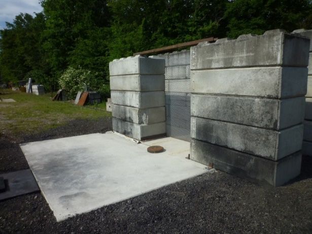
Appl. Sci. 2021, 11, 6539                                                                                          2 of 13

                            overpressure was measured on the shock wave path. The reflected overpressure was also
                            measured on a wall located 5 m behind the ring mesh. For the ring mesh alone, they
                            described an initial side-on overpressure reduction of approximately 17% at 50 cm behind
                            the grid and of around 1–6% at 1.5–2.5 m behind the grid. When the ring mesh was covered
                            by water, the initial side-on overpressure was reduced by 56% close behind the ring mesh
                            and by 20% 5 m behind the mesh. As regards the positive impulse, the ring mesh itself
                            caused no reduction. However, a reduction of about 17–31% was obtained behind the mesh
                            by adding a water curtain. The reflected pressure on the wall was slightly decreased by the
                            ring mesh but the addition of a water cover did not improve the attenuation performance.
                            In the second study [7], a transonic shock tube was used to visualize the interaction of
                            a blast wave profile with a metallic perforated plate or with a metallic perforated plate
                            covered by a layer of water. Free-field air blast experiments were also performed. Three
                            grid types with different porosities were tested. The highest attenuation was obtained with
                            the grid having the lowest porosity. The attenuation was of the order of 17–25% 25 cm
                            downstream from the grid and about 25–30% 3 m downstream from the grid. When the
                            grids were covered by a water layer, the initial overpressure behind the plate was reduced
                            for all grid types. The blast mitigation was improved, especially with the grids having
                            a high porosity. Again, the most pronounced reduction (about 35 to 48%) was obtained
                            with the grid having the lowest porosity. The initial overpressure 3 m downstream was
                            also reduced by about 20–30%. The impulse was also reduced by the grids with or without
                            a water film cover. Consequently, this blast mitigation method appears promising but
                            still needs some further work and improvement. The porosity of the plate is an important
                            factor to take into account in the blast mitigation performance and a water cover on the
                            plate increases even more the blast attenuation. The plate should have a relatively low
                            porosity. The use of a configuration with two plates could also represent an option for
                            improvement. Indeed, it has been shown that shock wave trapping between two perforated
                            plates enhanced the shock wave attenuation downstream from the grids [8].
                                  In this paper, the assessment of this blast mitigation solution made of perforated
                            plates with or without a water cover was further investigated in order to have a better
                            understanding of its mechanism and to improve its performance. Grids made of expanded
                            metal, with or without a water film, served as an obstacle. Expanded metal has an in-
                            teresting geometry that enhanced the reflection of the shock wave, and a low porosity.
                            First, an explosive-driven shock tube (EDST) was used to visualize the interaction of a
                            blast wave profile with one or two plates made of expanded metal, using a retroreflective
                            shadowgraph technique. Indeed, the propagation of blast waves in complex media is an
                            important topic of shock wave research and there is a need to study wave phenomena in
                            complex environments. EDSTs generates high dynamic loadings compared to conventional
                            shock tubes. Their mitigation capacity could be assessed under a load comparable to that
                            produced by several kilos of high explosives, located several meters from a target. Secondly,
                            free-field air blast experiments were performed in order to evaluate the protection system
                            under real conditions. Configurations with either one or two grids were investigated. The
                            case in which a film of water was added on the grid, or on the first grid in the case of a
                            two-grid configuration, was also studied. The transmitted pressure was measured on a
                            wall placed behind the plate(s) and the shock wave reflection by the plate was assessed
                            using a sensor located on the ground in front of the first grid.

                            2. Materials and Methods
                            2.1. Samples
                                  Grids made of expanded metal were investigated (Figure 1). Expanded metal is a
                            metal sheet that has been cut and stretched to form a regular pattern. Expanded metal
                            is stronger than an equivalent weight of wire mesh because the material is deformed,
                            allowing the metal to remain as a single piece. The expanded metal used in the present
                            study had a hexagonal mesh. The characteristics were an open area of 24%, a hole size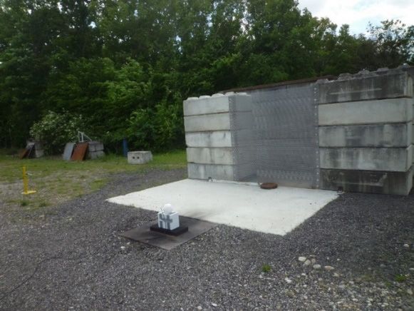
2. Materials and Methods
2.1. Samples
Grids made of expanded metal were investigated (Figure 1). Expanded metal is a
Appl. Sci. 2021, 11, 6539 metal sheet that has been cut and stretched to form a regular pattern. Expanded 3 of 13
metal is
stronger than an equivalent weight of wire mesh because the material is deformed, allow-
ing the metal to remain as a single piece. The expanded metal used in the present study
hadofa 45
hexagonal
mm × 13 mesh.
mm, a The characteristics
thickness of 3 mm, anwere an open
apparent area ofof24%,
thickness 9 mma and
holea size of 45
strand of mm
× 135 mm,
mm. a thickness of 3 mm, an apparent thickness of 9 mm and a strand of 5 mm.
(a) (b)
FigureFigure
1. (a) Piece of expanded
1. (a) Piece metal;
of expanded (b)(b)
metal; detail: open
detail: openarea
areaof
of24%, holesize
24%, hole sizeofof4545mm
mm× ×1313 mm,
mm, thickness
thickness of 3of 3 mm,
mm, apparent
apparent
thickness of 9 mm,
thickness strand
of 9 mm, of 5ofmm.
strand 5 mm.
2.2. Explosive Driven Shock Tube
2.2. Explosive Driven Shock Tube
The EDST was based on previously published works [9,10]. The shock tube has a
The EDST
square externalwas based
section on mm
of 100 previously
× 100 mm, published works [9,10].
a square internal section The
of 80 shock
mm × tube80mmhas a
square
and a total length of 1750 mm (Figure 2). A pressure sensor (Kulite HKS 375) was used× to
external section of 100 mm × 100 mm, a square internal section of 80 mm 80mm
andmeasure
a total length of 1750
the reflected mm (Figure
pressure 2).behind
at a wall A pressure sensor
the plates. (Kulite HKS
A spherical charge375)of was used to
C4 was
used (m
measure the= reflected
15 g) to produce
pressure a planar blast behind
at a wall wave. All thethe charges
plates. A were cast and
spherical detonated,
charge of C4 was
without
used (m = 15 anyg)container,
to produce 50 amm fromblast
planar the shock
wave. tube
Allinlet (Figure 2).
the charges A part
were castofand
the detonated,
initial
without any container, 50 mm from the shock tube inlet (Figure 2). A part of shock
spherical blast wave enters in the tube. At the tube inlet, the surface of the incident the initial
has a square curved shape which will be flattened as the shock travels through the tube.
spherical blast wave enters in the tube. At the tube inlet, the surface of the incident shock
The initial spherical blast wave becomes almost completely planar after about 1.5 m of
haspropagation,
a square curved shape which will be flattened as the shock travels through the tube.
leading to an initial uniform loading at the outlet of the shock tube. The blast
Theprofile
initialobtained
spherical blast
in this waywave becomes
is realistic and almost completely
in line with planar after about 1.5 m of
real threats.
propagation, leading
The distance to an initial
between uniform
the outlet of theloading
EDST and at the outlet
the wall of 180
was the mm.
shock Thetube. The
plate, or blast
profile obtained
the last plate ininthe
this way
case is realistic
of two and positioned
plates, was in line with 50 real
mm threats.
in front of the wall. Where
two
Theplates
distancewerebetween
used, thethespacing
outletbetween the plates
of the EDST andwasthe 40 mm.
wall wasThe180grid
mm. holes
Thewere
plate, or
always aligned directionally.
the last plate in the case of two plates, was positioned 50 mm in front of the wall. Where
two plates were used, the spacing between the plates was 40 mm. The grid holes were
2.3. Imaging for EDST
always aligned directionally.
A high speed Photron SA-Z camera was used to record images of the propagation and
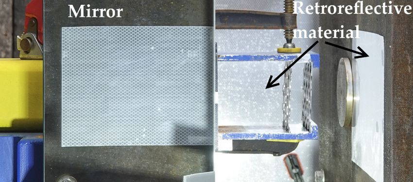
of the interaction of the shock wave with the plate(s) using a retroreflective shadowgraph
technique [11]. An extreme high power light emitting diode (LED) (XHP70.2, CREE),
located on an axis with the center of the camera lens, illuminated the outlet of the EDST
and a panel covered by a retroreflective material (3M Reflexfolie 4090) which was placed
in the background. Figure 3 shows a photograph of the camera with the LED and the
EDST and the Figure 2 shows the position of the retroreflective panel relative to the EDST
and the camera. A power supply and a purpose-built trigger unit allowed the LED to be
pulsed for about 10 ms. The reflection and the transmission patterns of the shock wave
through the obstacle could be visualized via their shadow on the panel. Moreover, a piece
of retroreflective material was plastered on the wall and a 45-degree inclined mirror was
attached to the end of the EDST (Figure 4). The camera filmed the panel placed in the
background but also the mirror, allowing for the visualization of the shock wave in the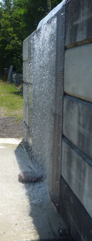
Appl. Sci. 2021, 11, 6539 4 of 13
Appl. Sci. 2021, 11, x FOR PEER REVIEW 4 of 14
axial direction. The videos were recorded with a frame rate of 100,000 fps at a resolution of
408 × 384 pixels.
Figure 2. Schematic view of the explosive-driven shock tube and positioning of the pressure sensor
and plates. The position of the high speed camera and of the retroreflective panel is also shown.
2.3. Imaging for EDST
A high speed Photron SA-Z camera was used to record images of the propagation
and of the interaction of the shock wave with the plate(s) using a retroreflective shadow-
graph technique [11]. An extreme high power light emitting diode (LED) (XHP70.2,
CREE), located on an axis with the center of the camera lens, illuminated the outlet of the
EDST and a panel covered by a retroreflective material (3M Reflexfolie 4090) which was
placed in the background. Figure 3 shows a photograph of the camera with the LED and
the EDST and the Figure 2 shows the position of the retroreflective panel relative to the
EDST and the camera. A power supply and a purpose-built trigger unit allowed the LED
to be pulsed for about 10 ms. The reflection and the transmission patterns of the shock
wave through the obstacle could be visualized via their shadow on the panel. Moreover,
a piece of retroreflective material was plastered on the wall and a 45-degree inclined mir-
ror was attached to the end of the EDST (Figure 4). The camera filmed the panel placed in
the background but also theexplosive-driven
mirror, allowing for tube
the visualization of the shock wave in
Figure2.2.Schematic
Figure Schematicview
viewofofthe
the explosive-drivenshock
shock tubeandandpositioning
positioningofofthe
thepressure
pressuresensor
sensor
the
and axial direction. The videos were recorded with a frame rate of 100,000 fps at a resolu-
andplates.
plates.The
Theposition
positionofofthe
thehigh
highspeed
speedcamera
cameraand
andofofthe
theretroreflective
retroreflectivepanel
panelisisalso
alsoshown.
shown.
tion of 408 × 384 pixels.
2.3. Imaging for EDST
A high speed Photron SA-Z camera was used to record images of the propagation
and of the interaction of the shock wave with the plate(s) using a retroreflective shadow-
graph technique [11]. An extreme high power light emitting diode (LED) (XHP70.2,
CREE), located on an axis with the center of the camera lens, illuminated the outlet of the
EDST and a panel covered by a retroreflective material (3M Reflexfolie 4090) which was
placed in the background. Figure 3 shows a photograph of the camera with the LED and
the EDST and the Figure 2 shows the position of the retroreflective panel relative to the
EDST and the camera. A power supply and a purpose-built trigger unit allowed the LED
Appl. Sci. 2021, 11, x FOR PEER REVIEW
Figure 3. View of
of the experimental setup, showingand
the explosive
explosive driven shock
shock tube and
and the5shock
of 14
high
to be 3.
pulsed forthe experimental
about setup,
10 ms. The showing
reflection the driven
the transmission tube
patterns the
of the high
speed
speed camera with the LED.
wavecamera withthe
through theobstacle
LED. could be visualized via their shadow on the panel. Moreover,
a piece of retroreflective material was plastered on the wall and a 45-degree inclined mir-
ror was attached to the end of the EDST (Figure 4). The camera filmed the panel placed in
the background but also the mirror, allowing for the visualization of the shock wave in
the axial direction. The videos were recorded with a frame rate of 100,000 fps at a resolu-
tion of 408 × 384 pixels.
Figure 4.
4. View
View of
of the
the EDST
EDST end
end showing
showing the
the panel
panel in
in the
the background,
background, the
the piece
piece of
of retroreflective
retroreflective
material plastered on the wall and the 45-degree inclined mirror.
material plastered on the wall and the 45-degree inclined mirror.
2.4. Free Field
Figure 3. View of the experimental setup, showing the explosive driven shock tube and the high
Explosion
speed tests
camera with thewere
LED.conducted with spheres of 2 kg C4. The charges were raised by
25 cm and ignited by a high voltage cap (RP 501) (Figure 5). Configurations with either
one or two grids were investigated. The addition of a film of water on the grid, or on the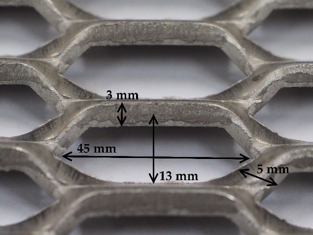
Figure 4. View of the EDST end showing the panel in the background, the piece of retroreflective
material plastered on the wall and the 45-degree inclined mirror.
Appl. Sci. 2021, 11, 6539 5 of 13
2.4. Free Field
Explosion tests were conducted with spheres of 2 kg C4. The charges were raised by
252.4.
cmFreeandField
ignited by a high voltage cap (RP 501) (Figure 5). Configurations with either
one or Explosion
two gridstestswere investigated.
were conducted withThe spheres
addition of of
2 kga film of water
C4. The charges onwere
the raised
grid, orbyon the
25 cm
first gridandin ignited
the case byof a high voltage cap
a two-grid (RP 501) (Figure
configuration, was5).also
Configurations
tested. For withtestseither
with one
one grid,
theorcharge
two gridswaswere investigated.
positioned 3.8 mThe addition
from the gridof aand
film4.8
of m
water
from onthe
thewall
grid,(Figure
or on the6).first
For tests
with two grids, the charge was positioned 3 m from the first grid, 3.8 mone
grid in the case of a two-grid configuration, was also tested. For tests with grid,
from thesecond
the
charge was positioned 3.8 m from the grid and 4.8 m from the wall (Figure 6). For tests with
one and 4.8 m from the wall (Figure 5). When paired, grids were spaced 0.8 m apart. The
two grids, the charge was positioned 3 m from the first grid, 3.8 m from the second one and
grid
4.8 size
m fromwasthe2m wall× 3(Figure
m and5).concrete blocks
When paired, placed
grids wereatspaced
the left0.8and rightThe
m apart. of the
gridgrids
size were
used
wasto 2mmount
× 3 mthem (Figuresblocks
and concrete 5 and placed
6). Eachat had theand
the left following
right of dimensions:
the grids werelengthused to160 cm,
height
mount them (Figures 5 and 6). Each had the following dimensions: length 160 cm, height 5), lo-
40 cm and width 80 cm. One side-on pressure gauge (PCB137A23) (Figure
cated
40 cm atand
a right
width angle
80 cm. to One
the shock
side-onwave’s
pressure propagation toward (Figure
gauge (PCB137A23) the wall, 5), allowed
located atfora veri-
right angle to the shock wave’s propagation toward the wall, allowed
fication of reproducibility. One PCB sensor (M102A) was used to evaluate the effect of the for verification of
reproducibility.
grids One PCB
or, of the grids sensorby
covered (M102A)
a film was used toofevaluate
of water, the effect
the reflected of the grids
pressure or, of
on the wall lo-
the grids covered by a film of water, of the reflected pressure on the wall
cated behind the grid (Figure 7, left). The sensor was positioned at a height of 50 cm. One located behind the
grid (Figure 7, left). The sensor was positioned at a height of 50 cm. One pressure gauge
pressure gauge (M102A) was positioned on the ground in front of the first grid position
(M102A) was positioned on the ground in front of the first grid position (Figures 5–7, left).
(Figures 5–7,was
This gauge left). This 19.5
located gauge
cm was
from located 19.5 The
the first grid. cm from
heightthe firstgauge
of this grid.wasThe5 cm.
height
Theof this
gauge was 5 cm. The water layer was generated by
water layer was generated by a pool fountain (VidalXL) (Figure 8). a pool fountain (VidalXL) (Figure 8).
(a) (b)
Appl. Sci. 2021, 11, x FOR PEER REVIEW 6 of 1
Figure Figure (a) Photography
5. Photography
5. (a) of of
thetheexperimental
experimental setup;
setup; (b)
(b)Schematic
Schematicdiagram
diagram showing the the
showing charge, grids,
charge, concrete
grids, blocks,blocks,
concrete
gauge gauge in front
in front of the
of the grid
grid andandoneoneside-on
side-onpressure
pressure gauge,
gauge,placed atat
placed a right angle.
a right angle.
Figure6.6.View
Figure Viewofof
thethe
experimental
experimentalsetup showing
setup the one-grid
showing configuration:
the one-grid the grid the
configuration: position,
grid position
concrete
concreteblocks and
blocks gauge
and in front
gauge of the
in front of grid.
the grid.
Appl. Sci. 2021, 11, 6539                                                                                                             6 of 13
                                Figure 6. View of the experimental setup showing the one-grid configuration: the grid position,
                                  Figureblocks
                                concrete  6. View of gauge
                                                and  the experimental   setup
                                                           in front of the     showing the one-grid configuration: the grid position,
                                                                            grid.
                                  concrete blocks and gauge in front of the grid.

                                     (a)(a)                                                         (b)
                                                                                                    (b)
     Figure
Figure
    Figure  7.  (a) Reflected
               (a)  Reflected
             7.Reflected
        7. (a)                pressure
                           pressure
                              pressure gauge
                                     gauge
                                        gaugelocated
                                            located
                                              locatedon
                                                     on
                                                      on  thewall
                                                        the  wall
                                                              wallbehind
                                                                  behind the
                                                                    behindthegrids;
                                                                           the      (b)(b)
                                                                               grids;
                                                                                grids;   pressure
                                                                                        (b)       gauge
                                                                                            pressure
                                                                                            pressure    located
                                                                                                     gauge
                                                                                                     gauge      in front
                                                                                                             located
                                                                                                            located      of theofof
                                                                                                                      infront
                                                                                                                     in  front   first
                                                                                                                                    thefirst
                                                                                                                                   the   first
     grid
gridgrid  position.
     position.
         position.

                                  Figure8.8.First
                                  Figure     Firstgrid
                                                   gridequipped
                                                        equippedwith
                                                                 with  a pool
                                                                     a pool   fountain.
                                                                            fountain.
                                Figure 8. First grid equipped with a pool fountain.
                                  3. Results
                                  3.1. Explosive Driven Shock Tube
                                        Figure 9 shows the shock wave propagating at the outlet of the EDST when there was
                                  no perforated plate. The photographs were taken with high-speed imaging. Thanks to the
                                  mirror, set at 45◦ in front of the camera, imagery could be obtained from the axial direction
                                  simultaneously with the direct view. Consequently, events happening axially to the EDST
                                  outlet could be observed. The shock wave was not totally planar at the outlet of the tube;
                                  indeed, the two metallic plates, fixed parallel to the EDST at the end and which were used
                                  to clamp the perforated plates, reflected the shock wave (t = 1440 µs). These two plates had
                                  a shoulder at their ends which provided additional thrust for the fixation of the perforated
                                  plates. These shoulders can be seen in Figure 4 and the shock wave visibly interacts with
                                  them (t = 1520 µs). The shock wave emerging laterally from the EDST was visible in the
                                  mirror. It should be noted that the shock wave exited the EDST outlet immediately, but in
                                  the beginning the optical setup did not allow the observation of this expansion.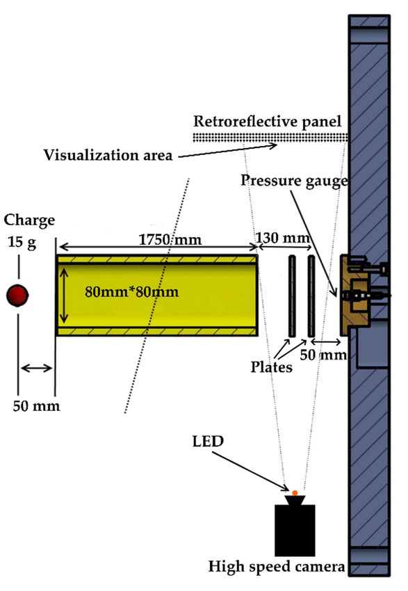
to clamp the perforated plates, reflected the shock wave (t = 1440 µs). These two plates
had a shoulder at their ends which provided additional thrust for the fixation of the per
forated plates. These shoulders can be seen in Figure 4 and the shock wave visibly inter
acts with them (t = 1520 µs). The shock wave emerging laterally from the EDST was visible
Appl. Sci. 2021, 11, 6539 7 of 13
in the mirror. It should be noted that the shock wave exited the EDST outlet immediately
but in the beginning the optical setup did not allow the observation of this expansion.
Figure9.9.Photographic
Figure Photographic results of high-speed
results videovideo
of high-speed recording, showing
recording, shock wave
showing propagation
shock at
wave propagation a
the
the outlet
outletofofthe
theEDST
EDST(20(20 between
µs µs betweeneacheach
photograph).
photograph).
Figure 10 shows shock wave propagation through one deployed metal plate. The plate
Figure 10 shows shock wave propagation through one deployed metal plate. The
was positioned at a distance of 130 mm from the tube outlet and at a distance of 50 mm in
plate was positioned at a distance of 130 mm from the tube outlet and at a distance of 50
front of the wall. At t = 1470 µs, the shock wave when passing through the plate apertures
mm into
split in front of shock
several the wall. At one
waves, t = 1470 µs,aperture,
for each the shockandwave
thesewhen
shockpassing through the plate
waves recombined
apertures split into several shock waves, one for each aperture,
further down. At t = 1530 µs, the shock wave behind the plate became almost planar and these shock waves
recombined
again. further
A complex down.ofAt
structure t = 1530 µs,
turbulence the shock
appeared wave behind
just behind the gridthe plate
and became almos
it persisted
planar again. A complex structure of turbulence appeared just behind the gridand
for some time; at t = 1510 µs turbulence began to form along the backside the grid, and it per
at t = 1790
sisted for µs it was
some stillat
time; observable.
t = 1510 µsThe reconbinated
turbulence shock
began to wave
form behind
along the perforated
the backside the 8grid
Appl. Sci. 2021, 11, x FOR PEER REVIEW of 1
plate hit the wall and was reflected at t = 1570 µs. The remaining shock wave,
and at t = 1790 µs it was still observable. The reconbinated shock wave behind the perfo which did
not pass through the grid and was reflected by it, became almost planar at t = 1550 µs.
rated plate hit the wall and was reflected at t = 1570 µs. The remaining shock wave, which
did not pass through the grid and was reflected by it, became almost planar at t = 1550 µs
Figure10.
Figure 10.Photographic
Photographic results
results of high-speed
of high-speed videovideo recording,
recording, showing
showing shock
shock wave wave propagation
propagation
throughone
through oneplate
plate
of of deployed
deployed metal
metal (20between
(20 µs µs between each photograph).
each photograph).
Figure 11 shows shock wave propagation through two deployed metal plates. Th
first plate was positioned at a distance of 90 mm from the tube outlet and at a distance o
90 mm in front of the wall. Grids were paired 40 mm apart. When passing through th
apertures of the first plate (t = 1450 µs), the shock wave split into several shock waves, on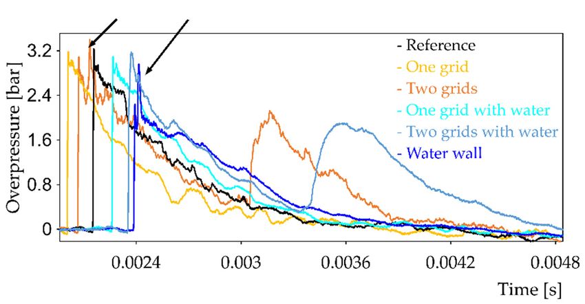
Figure 10. Photographic results of high-speed video recording, showing shock wave pro
through one plate of deployed metal (20 µs between each photograph).
Appl. Sci. 2021, 11, 6539 8 of 13
Figure 11 shows shock wave propagation through two deployed metal pla
first plate was positioned at a distance of 90 mm from the tube outlet and at a dis
90 mm in front of the wall. Grids were paired 40 mm apart. When passing thro
Figure 11 shows shock wave propagation through two deployed metal plates. The
apertures
first plate wasofpositioned
the first plate (t = 1450
at a distance of 90µs),
mm the
fromshock wave
the tube split
outlet into
and at aseveral
distanceshock
of wa
formm
90 each aperture,
in front andGrids
of the wall. thesewereshockpairedwaves
40 mmrecombined furtherthrough
apart. When passing down.the The tran
shock wave was similar to the incident shock wave at t = 1490 µs. At the back of th
apertures of the first plate (t = 1450 µs), the shock wave split into several shock waves,
one
wave, for each aperture,
between theand
two these shocklasting
plates, waves recombined
turbulence further
could down. The transmitted
be observed, especially i
shock wave was similar to the incident shock wave at t = 1490 µs. At the back of the shock
ately behind the first plate. The remaining shock wave, which did not pass thro
wave, between the two plates, lasting turbulence could be observed, especially immediately
first plate,
behind was
the first reflected,
plate. leadingshock
The remaining to the pattern
wave, which captured
did not passat the backthe
through of this
first plate. T
ter, the
plate, wasshock wave
reflected, transmitted
leading to the patternbycaptured
the firstat plate impacted
the back theThereafter,
of this plate. second plate
the (t =
shock wave transmitted by the first plate impacted the second plate
and, once again, a part of the shock wave was transmitted and part was reflec (t = 1510 µs) and, once
again, a part of the shock wave was transmitted and part was reflected. The wave reflected
wave reflected by the second plate propagated toward the first plate and, as it
by the second plate propagated toward the first plate and, as it arrived near the plate, the
near the
shock frontplate,
and the the shock front
turbulence becameandlessthe turbulence
obvious. We couldbecame
also seeless obvious.
turbulence We could
behind
turbulence
the second plate.behind the second plate.
Figure11.11.
Figure Photographic
Photographic results
results of high-speed
of high-speed video recording,
video recording, showing
showing shock shock wave
wave propagation prop
through
through one
oneplate of deployed
plate metal (20
of deployed µs between
metal (20 µs each photograph).
between each photograph).
Five reference tests were conducted without any plates and seven experiments were
Fivewith
conducted reference tests
either one were
or two conducted
grids positionedwithout anyofplates
at the outlet and
the EDST. seven
The experimen
reflected
conducted versus
overpressure with either one
time was or twobygrids
collected positioned
the sensor insertedat
in the outlet
the wall of the
behind theEDST.
plate. The r
The blast wave propagation through the shock tube was computed with Autodyn (ANSYS)
and the overpressure at the outlet of the shock tube was obtained. The calculated initial
overpressure was 32 bar. The measured value at a distance of 180 mm was ~18 bar, which
was consistent with simulation. The impulse, which is the pressure signal integrated over
time, as a function of time, was also computed. Figure 12a presents the reflected pressure
as a function of time, obtained in a reference test and in one test each using one or two
expanded metal plates. When the number of plates increased, the reduction of the initial
reflected overpressure increased. The initial overpressure reflected on the wall was reduced
by 46% and 72%, respectively, when either one or two plates were positioned in front
of the EDST (Table 1). Correspondingly, the maximum impulse was reduced by 68 and
89% (Table 1).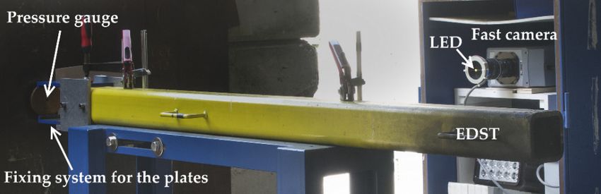
flected pressure as a function of time, obtained in a reference test and in one test each
using one or two expanded metal plates. When the number of plates increased, the reduc-
tion of the initial reflected overpressure increased. The initial overpressure reflected on
the wall was reduced by 46% and 72%, respectively, when either one or two plates were
Appl. Sci. 2021, 11, 6539 positioned in front of the EDST (Table 1). Correspondingly, the maximum impulse9 of 13 was
reduced by 68 and 89% (Table 1).
(a) (b)
Figure 12. 12.
Figure Reflected pressure
Reflected pressure(a)(a)and
andimpulse
impulse(b)(b)measured on the
measured on the wall
wallpositioned
positioned5050mm mm behind
behind either
either oneone or two ex-
or two
panded metalmetal
expanded plates. OneOne
plates. reference
referencetest, which
test, whichwas
wasperformed withoutplates,
performed without plates,is is also
also shown.
shown.
Table
Table 1. Initial
1. Initial reflectedoverpressure
reflected overpressure and
andmaximum
maximum impulse collected
impulse by theby
collected sensor insertedinserted
the sensor in the wall
inand
thelocated 50 mm
wall and located 50
mmdownstream
downstream from the perforated
from plates plates
the perforated for all experiments. The difference
for all experiments. from the mean
The difference fromvalue
theobtained with the
mean value reference
obtained with the
tests (no
reference plate)
tests (noisplate)
also given.
is also given.
TypeType
of Plate
of Plate Number ofof
Number Plates Overpressure
Plates Overpressure (Bar) Attenuation
(Bar) Attenuation (%) (%) (Bar·s) (Bar.s)
Impulse
Impulse Attenuation
Attenuation (%) (%)
no plate
no plate - - 22.82
22.82 - - 0.0032 0.0032 - -
no plate
no plate - - 19.48
19.48 - - 0.0040 0.0040 - -
no plate
no plate - - 15.61
15.61 - - 0.0035 0.0035 - -
no plate - 15.65 - 0.0037 -
no plate
no plate
- - 15.65
15.73 -
- 0.0034
0.0037 -
-
no plate metal
expanded - 1 15.73
9.36 48 - 0.0011 0.0034 70 -
expanded metal
expanded metal 11 9.36
7.71 57 48 0.0012 0.0011 65 70
expanded
expanded metal
metal 11 10.89
7.71 39 57 0.0013 0.0012 63 65
expanded metal
expanded metal 11 10.30
10.89 42
39 0.0015
0.0013 59
63
expanded metal 2 4.46 75 0.0003 93
expanded metal
expanded metal 12 10.30
4.50 75 42 0.0005 0.0015 87 59
expanded metal
expanded metal 22 4.46
5.86 67 75 0.0005 0.0003 87 93
expanded
expanded metal
metal 22 4.46
4.50 75 75 0.0003 0.0005 93 87
expanded metal 2 5.86 67 0.0005 87
expanded metal 23.2. Free Field 4.46 75 0.0003 93
The initial overpressure and the maximum impulse obtained through the control
3.2. Freefor
gauge Field
all experiments are presented in Tables 2 and 3, respectively. These measurements
showed
The that thereoverpressure
initial was rather good reproducibility.
and the maximum The impulse
side-on overpressure was estimated
obtained through the control
with Kingery’s and Bulmash’s formula [12]. The detonation of 2 kg of C4 generates an
gauge for all experiments are presented in Tables 2 and 3, respectively. These measure-
overpressure of 0.8 bar at a distance of 5 m. The measured values were consistent with
ments showed that there was rather good reproducibility. The side-on overpressure was
this value. Figure 13 presents the overpressure measured on the wall for one test of each
estimated withTwo
configuration. Kingery’s
or threeand Bulmash’s
experiments wereformula [12].for
conducted The detonation
each of 2 kg
configuration. of 2C4 gen-
Table
erates an overpressure of 0.8 bar at a distance of 5 m. The measured values
gives the initial overpressure value obtained in all the tests. According to Kingery’s and were consistent
with this value.
Bulmash’s formulaFigure
[12], 13
thepresents
detonationthe
of overpressure measured
2 kg of C4 generates on the
a reflected wall for one
overpressure of test of
2.6 bar at a distance of 4.8 m. The measured values were consistent with this
each configuration. Two or three experiments were conducted for each configuration. Ta- value. The
overpressure
ble 2 gives thewas reduced
initial when onevalue
overpressure plate was located
obtained inin
allfront of the According
the tests. wall, in the to
order
Kingery’s
of 32–47%. Adding a second plate on the shock wave path led to a stronger
and Bulmash’s formula [12], the detonation of 2 kg of C4 generates a reflected overpres- attenuation.
The initial overpressure was reduced by about 62–66%. When a water film was used, the
sure of 2.6 bar at a distance of 4.8 m. The measured values were consistent with this value.
reflected overpressure on the wall was reduced even more, especially in the case of the
one-plate configuration. The reduction of overpressure was about 69–71% and 66–74%
for one-plate configurations and two-plate configurations, respectively. The setup using
a water wall alone was also evaluated and the reflected overpressure on the wall was
not modified. Figure 14 presents the impulse measured on the wall for one test of each
configuration and Table 3 gives the maximum impulse values obtained for all tests. The
results were similar to those observed for overpressure.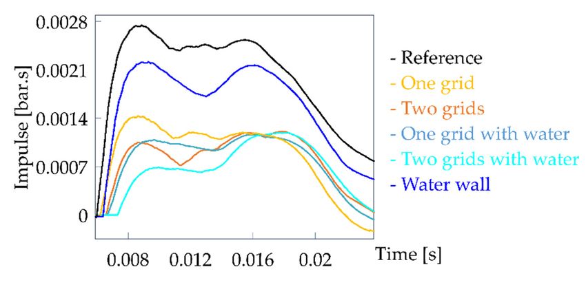
Appl. Sci. 2021, 11, 6539                                                                                                       10 of 13

         Table 2. Initial overpressure collected by three sensors (control, inserted into the wall and laid on the ground) for all
         experiments. The attenuation of the overpressure measured on the wall relative to the mean value obtained by the reference
         tests (no plate) is also given. Overpressure ground 1 and overpressure ground 2 correspond to the maximum value of the
         first and the second peak, respectively.

                                    Overpressure        Overpressure                             Overpressure         Overpressure
          Experiment Type                                                  Attenuation (%)
                                    Control (Bar)        Wall (Bar)                              Ground 1 (Bar)       Ground 2 (Bar)
              no plate                   0.90                2.53                  -                   3.20                   -
              no plate                   0.89                2.61                  -                   3.22                   -
              no plate                   0.89                2.70                  -                     -                    -
         2 expanded metal                0.90                1.05                 60                   3.08                 2.12
         2 expanded metal                0.86                0.88                 66                   2.26                 1.96
         2 expanded metal                0.89                0.99                 62                   3.31                 2.14
     2 expanded metal & water            0.89                0.90                 66                   1.88                 1.89
     2 expanded metal & water            0.78                0.68                 74                   3.17                 1.83
         1 expanded metal                0.89                1.42                 46                   3.16                   -
         1 expanded metal                0.82                1.78                 32                   3.52                   -
         1 expanded metal                0.84                1.40                 47                   3.62                   -
     1 expanded metal & water            0.80                0.82                 69                   2.80                   -
     1 expanded metal & water            0.76                0.75                 71                   3.08                   -

         Table 3. Maximum impulse collected by the three sensors (control, inserted into the wall and laid on the ground) for all
         experiments. The attenuation of impulse measured on the wall relative to the mean value obtained by the reference tests (no
         plate) is also given. Impulse ground 1 and impulse ground 2 correspond to the maximum value of the first and the second
         peak, respectively.

                                  Impulse Control       Impulse Wall         Attenuation       Impulse Ground        Impulse Ground
          Experiment Type
                                      (Bar·s)             (Bar·s)                (%)              1 (Bar·s)             2 (Bar·s)
               no plate                0.00103              0.00247                -               0.001427                  -
               no plate                0.00105              0.00275                -               0.001388                  -
               no plate                0.00097              0.00261                -                   -                     -
          2 expanded metal             0.00108              0.00105               60               0.001384              0.002338
          2 expanded metal             0.00108              0.00105               60               0.001287              0.002258
          2 expanded metal             0.00105              0.00095               64               0.001127              0.001849
    2 expanded metal & water           0.00104              0.00077               71               0.001312              0.002546
    2 expanded metal & water           0.00098              0.00071               73               0.001143              0.002234
           1 expanded metal           0.00107               0.00155               41               0.001411                  -
           1 expanded metal           0.00100               0.00144               45               0.001395                  -
           1 expanded metal           0.00096              0.001437               45               0.001289                  -
Appl. Sci. 2021, 11, x FOR PEER REVIEW                                                                                                        11 of 14
     1 expanded metal & water         0.00094               0.00108               58               0.001418                  -
     1 expanded metal & water         0.00093               0.00110               58               0.001402                  -

                                             13.Reflected
                                    Figure 13.
                                    Figure       Reflectedpressure
                                                           pressuremeasured on the
                                                                     measured   on wall for one
                                                                                   the wall  fortest
                                                                                                 oneoftest
                                                                                                       eachofconfiguration. One reference
                                                                                                              each configuration.   One reference
                                    test is
                                    test is also
                                            alsoshown.
                                                 shown.
Figure 13. Reflected pressure measured on the wall for one test of each configuration. One referenc
test is also shown.
Appl. Sci. 2021, 11, 6539 11 of 13
Figure 13. Reflected pressure measured on the wall for one test of each configuration. One reference
test is also shown.
Figure 14. Reflected impulse measured on the wall for one test of each configuration. One referenc
test is also shown.
Figure 14. Reflected impulse measured on the wall for one test of each configuration. One reference
test is Figure
Figure also 15 presents
shown.
14. Reflected the
impulse overpressure
measured on the measured
wall for oneby the
test ofgauge positioned on
each configuration. Onethe ground
reference
test is also
at the firstshown.
plate’s position. The reflection of the shock wave, when a plate was placed nea
Figure 15 presents the overpressure measured by the gauge positioned on the ground
this
at thesensor (two-plate
first plate’s configuration),
position. could
The reflection of be observed
the shock (seea the
wave, when platearrows in the
was placed Figure 15)
near
Figure 15 presents the overpressure measured by the gauge positioned on the
this sensor (two-plate configuration), could be observed (see the arrows in the Figure 15). and the
In case of one-plate configurations, the sensor was placed further off the plate ground
at the
shock
In first
case of wave plate’s position.
reflection
one-plate The reflection
was not perceptible.
configurations, of the shock
the sensor wasInplaced wave,
the case when
of two-plate
further a plate was placed
configurations,
off the plate and the shock the near
re
this sensor (two-plate configuration), could be observed (see the arrows
flection of the shock wave on the second plate was clearly manifested as a huge overpres
wave reflection was not perceptible. In the case of two-plate configurations, thein the Figure
reflection 15).
In
of case
sure of one-plate
thesecond
shock peak.onconfigurations,
wave the second platethewassensor
clearlywas placed as
manifested further
a hugeoff the plate and the
overpressure
shock
secondwave peak.reflection was not perceptible. In the case of two-plate configurations, the re-
flection of the shock wave on the second plate was clearly manifested as a huge overpres-
sure second peak.
Figure 15.Overpressure
Figure15. Overpressure obtained by the
obtained by gauge laid on
the gauge theon
laid ground for onefor
the ground testone
of each
test configuration.
of each configuration
One reference test is also shown.
One reference test is also shown.
4. Discussion
4. Discussion
Figure 15. Overpressure obtained by the gauge laid on the ground for one test of each configuration.
Shock wave propagation through one or two deployed metal plate(s) was observed
One reference test is also shown.
thanks to the EDST and a retroreflective shadowgraph technique. This experimental set-up
was very well suited to this research, since the shock wave interaction with perforated
4.plates
Discussion
could be assessed with high loading and visualized at the same time. This is not
possible when using a conventional shock tube, the blast loading being rather moderate.
In any event, it is not possible to use high Mach numbers when the air flow in the shock
tube is especially blocked, due to risk of damage. Understanding of the complex flow
field induced by blast that passes through a complex media is an important aspect in
blast mitigation research and could help to design new devices for protection against blast
loading. The shock wave, when it passed through the apertures of a deployed metal plate,
split into several shock waves, one for each aperture, which recombined further on. A
complex structure of turbulence appeared just behind the grid and it persisted for some
time. The remaining shock wave, which did not pass through the grid, was reflected by the
grid. In the case of two plate configurations, the shock wave had time to reform between
the two plates, which impacted the second plate. Once again, a part of the shock wave was
transmitted and part was reflected. Turbulence behind the second plate was also visible.Appl. Sci. 2021, 11, 6539 12 of 13
The shock wave reflection and the creation of turbulence led to a blast wave attenuation.
Consequently, when two plates served as an obstacle, these phenomena occurred twice
and the mitigation was greater. This was confirmed by the reflected overpressure and
impulse measured by the sensor inserted into the wall behind the plate(s). When the
number of plates increased, these values were reduced. Similar observations were made
by O. Ram et al. [13], who assessed the propagation of shock waves through an array
of perforated plates in a conventional shock tube. Thus, we can conclude that similar
phenomena occurred at low (3 bar) and high loading (20 bar).
The results obtained in free field were consistent with the results obtained by means of
the EDST. The reflected overpressure and impulse measured behind one plate on a wall was
reduced ion the order of 32–47%. The addition of a second plate on the shock wave path led
to a stronger attenuation (62–66%). When a water film was used, the reflected overpressure
on the wall was reduced still more, especially in the case of one-plate configurations—the
mitigation approached that obtained from two-plate configurations. The water cover had
only a small effect on blast mitigation when two plates were used. We can conclude that the
water layer’s contribution mostly enhanced the reflection of the shock wave by filling the
apertures with water. When one perforated plate was covered with a water film, its capacity
to reflect the blast wave was enhanced, its performance to mitigate the blast increased and
approached that obtained from two-plate configurations. In cases with two plates, the
obstruction of the blast wave was rather high, and the addition of a water cover induced
only a modest improvement. In [7], thanks to a transonic shock tube, the interaction of a
blast wave with a perforated plate with a water cover was imaged and it was observed
that the water film disintegrated into droplets significantly after the shock wave front had
passed through it. The fragmentation of the water film had little effect on the attenuation,
as it broke long after the passage of the shock wave front and there is little extraction of
energy from the shock front from water layer fragmentation. In this work, the results have
also shown that a water wall alone had almost no impact on the reflected overpressure on
the wall. Moreover, the study [4] on blast mitigation using a water wall, in which walls
made of plastic bags, filled with water and having a thickness of 5 to 8 cm, it was shown
that the mitigation was obtained by obstruction, reflection and diffraction of the blast wave.
The mitigation mechanism was comparable to that of a rigid wall, thus the mitigating
effect of energy exchange with water was not primarily responsible for the effect. The
results obtained here could also be compared to those obtained by Gebbeken et al. [6] and
Xiao et al. [5]. In these two studies, blast mitigation observed when using a single grid was
very low and this could be explained by the high porosity of the grids used. Indeed, the
first study [6] used a stainless steel ring mesh with a porosity of 63% and, in the second,
a woven wire mesh having a relative opening fraction of 60.2%. In the setup using ring
mesh, adding a water curtain also enhanced the attenuation of both peak overpressure
and positive impulse. The authors also claimed that when a blast wave hits ring mesh
covered by water, the water layer forms a closed surface that reflects the blast wave to a
greater extent.
In the case of a higher-charge explosive, the phenomenon of shock wave transmis-
sion/reflection would likely be the same and equivalent mitigation performance would be
achieved. However, if the grids are not sufficiently resistant to a high loading, the grids
could deform and tear. Some debris could impact the structure behind such grids, and
consequently the use of gridded plates could have prejudicial effects. The grids and their
attachment system must be sized to guarantee their resistance and their structural integrity
with respect to anticipated blast size.
5. Conclusions
In this paper, we have assessed a blast mitigation solution made of perforated plates
with or without a water cover. The mitigation of a blast wave after its passage through one
or two plate(s) made of deployed metal, covered or not by a water film, was investigated.
First, we imaged the interaction of a blast wave with the grids at high loading. Secondly,Appl. Sci. 2021, 11, 6539 13 of 13
free-field air blast experiments were performed in order to evaluate the protection system
under real conditions. It was observed that the overpressure and the impulse downstream
of the grids were reduced and that the mitigation performance increased with the number of
plates. Adding a water layer to one grid contributed to its mitigation capacity. However in
setups with two plates, the addition of a water cover on the first grid induced only a modest
improvement. All in all, this method seems to warrant interest for protection purposes.
Author Contributions: Conceptualization, methodology, experimentations, data analysis, writing,
review and editing—T.S. Metrology, methodology, experimentations, data analysis—D.E. Both
authors have read and agreed to the published version of the manuscript.
Funding: This research received no external funding.
Institutional Review Board Statement: Not applicable.
Informed Consent Statement: Not applicable.
Data Availability Statement: The data are provided in the paper.
Acknowledgments: We thank our colleagues Yannick Boehrer, Thierry Ottié, Yannick Stehlin and
Sylvain Hemmerlin who assisted us in our research by providing technical support.
Conflicts of Interest: The authors declare no conflict of interest.
References
1. Kingery, C.; Pearson, R.; Coulter, G. Shock Wave Attenuation by Perforated Plates with Various Hole Sizes. USA Ballistic
Research Laboratory Memorandum Report; 1977; n◦ 2757, Defense Technical Information Center. Available online: https:
//apps.dtic.mil/sti/citations/ADA041854 (accessed on 18 June 2021).
2. Britan, A.; Karpov, A.V.; Vasilev, E.I.; Igra, O.; Ben-Dor, G.; Shapiro, E. Experimental and numerical study of shock wave
interaction with perforated plate. J. Fluids Mech. 2004, 126, 399–409. [CrossRef]
3. Britan, A.; Igra, O.; Ben-Dor, G.; Shapiro, E. Shock wave attenuation by grids and orifice plates. Shock Waves 2006, 16, 1–15.
[CrossRef]
4. Chen, L.; Zhang, L.; Fang, Q.; Mao, Y.-M. Performance based investigation on the construction of anti-blast water wall. Int. J.
Impact Eng. 2015, 81, 17–33. [CrossRef]
5. Xiao, W.; Andrae, A.; Gebbeken, N. Experimental investigations of shock wave attenuation performance using protective barriers
made of woven wire mesh. Int. J. Impact Eng. 2019, 131, 209–221. [CrossRef]
6. Gebbeken, N.; Rüdiger, L.; Warnstedt, P. Explosion mitigation by water mist-ring mesh with water curtain. In Proceedings of the
25th MilitaryAspects of Blast and Shock Conference, Hague, The Netherlands, 23–25 September 2018.
7. Schunck, T.; Bastide, M.; Eckenfels, D.; Legendre, J.-F. Explosion mitigation by metal grid with water curtain. Shock Waves 2021.
[CrossRef]
8. Seeraj, S. Shock Wave Interactions with Porous Plates. Master’s Thesis, University of the Witwatersrand, Johannesburg, South
Africa, 2007.
9. Louar, M.A.; Belkassem, B.; Ousji, H.; Spranghers, K.; Kakogiannis, D.; Pyl, L.; Vantomme, J. Explosive driven shock tube loading
of aluminium plates: Experimental study. Int. J. Impact Eng. 2015, 86, 111–123. [CrossRef]
10. Ousji, H.; Belkassem, B.; Louar, M.A.; Reymen, B.; Martino, J.; Lecompte, D.; Pyl, L.; Vantomme, J. Air-blast response of sacrificial
cladding using low density foams: Experimental and analytical approach. Int. J. Mech. Sci. 2017, 128–129, 459–474. [CrossRef]
11. Stojko, S.; Freundt, J.; Anderson, J.G.; Delaney, T. Experimental characterization of the interaction of blast waves from multiple
high explosive charges. In Proceedings of the 25th MilitaryAspects of Blast and Shock Conference, Hague, The Netherlands,
23–25 September 2018.
12. Kingery, C.N.; Bulmash, G. Technical Report ARBRL-TR-02555: Air Blast Parameters from TNT Spherical Air Burst and HEMISPHERI-
CAL Burst; AD-B082 713; U.S. Army Ballistic Research Laboratory: Aberdeen Proving Ground, MD, USA, 1984.
13. Ram, O.; Ben-Dor, G.; Sadot, O. On the pressure buildup behind an array of perforated plates impinged by a normal shock wave.
Exp. Therm. Fluid Sci. 2018, 92, 211–221. [CrossRef]You can also read