Fine Bauxite Recovery Using a Plate-Packed Flotation Column - MDPI
←
→
Page content transcription
If your browser does not render page correctly, please read the page content below
metals
Article
Fine Bauxite Recovery Using a Plate-Packed
Flotation Column
Pengyu Zhang 1,2 , Saizhen Jin 1,2 , Leming Ou 1,2, *, Wencai Zhang 3, * and Yuteng Zhu 1,2
 1   School of Minerals Processing and Bioengineering, Central South University, Changsha 410083, China;
     pengyu7765@csu.edu.cn (P.Z.); jinsaizhen@csu.edu.cn (S.J.); zhuyuteng@csu.edu.cn (Y.Z.)
 2   Key Laboratory of Hunan Province for Clean and Efficient Utilization of Strategic Calcium-Containing
     Mineral Resources, Central South University, Changsha 410083, China
 3   Department of Mining and Minerals Engineering, Virginia Polytechnic Institute and State University,
     Blacksburg, VA 24061, USA
 *   Correspondence: olmpaper@csu.edu.cn (L.O.); wencaizhang@vt.edu (W.Z.);
     Tel.: +86-0731-8883-0913 (L.O.); +540-231-6671 (W.Z.)

 Received: 2 August 2020; Accepted: 24 August 2020; Published: 2 September 2020

 Abstract: In this investigation, the fine-grained bauxite ore flotation was conducted in a plate-packed
 flotation column. This paper evaluated the effects of packing-plates on recovering fine bauxite
 particles and revealed the fundamental mechanisms. Bubble coalescence and break-up behaviors in
 the packed and unpacked flotation columns were characterized by combining Computational Fluid
 Dynamics (CFD) and Population Balance Model (PBM) techniques. Flotation experiments showed
 that packing-plates in the collection zone of a column can improve bauxite flotation performance
 and increase the smaller bauxite particles recovery. Using packing-plates, the recovery of Al2 O3
 increased by 2.11%, and the grade of Al2 O3 increased by 1.85%. The fraction of −20 µm mineral
 particles in concentrate increased from 47.31% to 54.79%. CFD simulation results indicated that the
 packing-plates optimized the bubble distribution characteristics and increased the proportion of
 microbubbles in the flotation column, which contributed to improving the capture probability of fine
 bauxite particles.

 Keywords: plate-packed flotation column; fine bauxite particles; bubble characteristics

1. Introduction
      Most of the valuable minerals in ores are required concentration to reduce the operation costs of
downstream extractive metallurgical processes. The concentration process is known as the key step
of mineral processing. In the field of mineral processing, recovering fine minerals is difficult thus
resulting in a lot of economic losses [1,2]. To solve these problems, column flotation technology has
been developed in the past few decades [3,4]. Due to the structural features, flotation columns usually
provide a higher recovery of fine minerals compared with other flotation equipment [5]. The mechanism
of a traditional countercurrent flotation column is to make bubbles and mineral particles move towards
each other, and then the hydrophobic particles are captured by the bubbles from the slurry, and rise
with the bubbles to a froth zone. With the continuous flow of bubbles, these captured mineral particles
gradually get out of the column. Consequently, the bubble size and distribution characteristics in
flotation column have significant effects on the concentration performance.
      After decades of progress, many different types of flotation columns have been derived and used
in the industrial processing of various minerals [6–8]. Flotation columns packed with plates have
specific internal structures, which impose direct effects on the flow characteristics of slurry inside the
column, thereby affecting the flotation process of minerals [9–11]. For instance, a honeycomb tube

Metals 2020, 10, 1184; doi:10.3390/met10091184                                    www.mdpi.com/journal/metals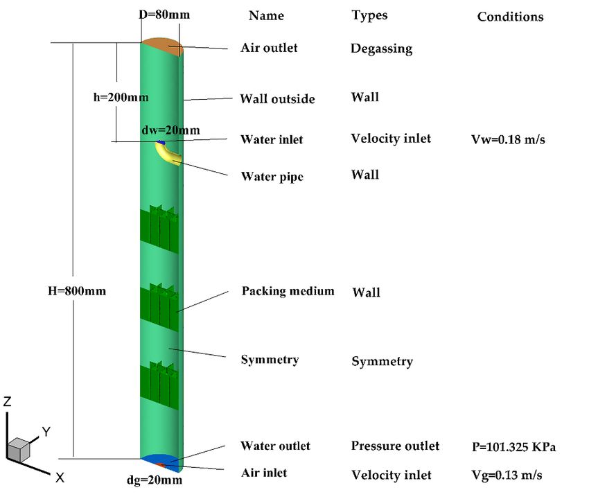
Metals 2020, 10, 1184 2 of 11
is designed as packing-plates in previous research works [12,13]. Experimental results showed that
honeycomb tube can promote the generation of smaller bubbles, thereby increasing gas content, as
well as particle–bubble collision probability. Moreover, the honeycomb tube packing causes turbulent
rotating flow into a mild flow in the column, forming a static hydrodynamic environment and reducing
the probability of detachment. The bubble behaviors was also investigated in a lab-scale cyclonic-static
micro-bubble flotation column packed by sieve plates [14]. Based on Particle Image Velocimetry (PIV)
and Charge-Coupled Device (CCD) camera techniques, it was found that packing non-uniform sieve
plates was more effective in terms of bubble distribution equalization, air column inhabitation, and
non-axial velocity decreasing.
In a previous study of fine bauxite ore column flotation [15], square packed-plates were installed
in the collection zone of a flotation column in a multi-layer packing manner. Based on flotation
experiments, the addition of packing-plates led to a better separation of bauxite from gangue minerals
and a higher recovery of fine mineral particles. Computational Fluid Dynamics (CFD) simulation
results indicated that the original intensively turbulent environment was weakened and dispersed
into several units with different turbulent intensities in axial, which enhanced the separation of
mineral particles with different properties. But the mechanism of improved recovery of fine mineral
particles by the packing-plates has not been fully described and presented. In this present work,
CFD combined with Population Balance Model (PBM) simulations were performed to characterize
the bubble coalescence and break-up behaviors in the unpacked flotation column (UFC) and the
plate-packed flotation column (PFC). Additionally, the effects of bubble diameter on recovering finer
bauxite particles was also evaluated.
2. Materials and Methods
2.1. Flotation Apparatus and Procedures
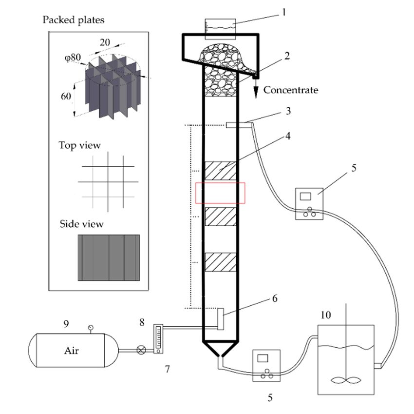
Flotation experiments were conducted using a squared-plates column flotation apparatus (Figure 1).
The flotation column has a dimension of ϕ80 mm × 2000 mm. This apparatus primarily consists of
three subsystems: a Plexiglas flotation column, an air injection system, and a slurry circulation system.
The packing-plates was made by polyethylene plates (thickness δ = 1 mm); its structure was shown
in different viewpoints (see Figure 1). Three layers of packing-plates were evenly installed along the
column between the slurry inlet and air inlet.
Experimental procedures of the column flotation tests were described as follows:
(1) Grind 2 kg of the bauxite ore (collected from a bauxite mine located in Henan Province, Luoyang,
China) until its average particle size (D50 ) reaches about 20 µm;
(2) Condition the feed slurry in the slurry mixing tank at room temperature and pH 9.5
(sodium carbonate as pH modifier). Add 100 g/t hexametaphosphate into the feed slurry
then stir for 3 min. Followed by adding 1200 g/t sodium oleate and conditioning for 4 min. All
three reagents are analytical grade supplied by Aladdin Biochem. Tech., Shanghai, China. The
initial slurry solid concentration is 15%;
(3) Turn on the air compressor (0.6 MPa), and adjust air inlet flowrate to 2.5 L/min; Turn on the
peristaltic pump, and adjust feed flowrate to 3.34 L/min. When foams start to flow out from the
top of the column, collect the froth product as concentrate K for a period of 12 min, after which
the slurry remaining in the column is collected in mixing tank as tailings X. The column flotation
test is running at batch mode;
(4) Filter and dry the concentrate K and tailings X, followed by elemental analysis using X-ray
fluorescence. Additionally, perform particle size analysis on the concentrate K using a laser particle
size analyzer (Mastersize 2000). Both instruments are from Malver Panalytical, Malvern, UK.
Additionally, bubbles were observed in an area circled in the red box shown in Figure 1. Due to
the problem of poor light transmittance during the flotation process of the bauxite ore, it was hard to
2. Materials and Methods
2.1. Flotation Apparatus and Procedures
Flotation experiments were conducted using a squared-plates column flotation apparatus
Metals
(Figure The10,flotation
1).2020, 1184 column has a dimension of 80 mm 2000 mm. This apparatus primarily 3 of 11
consists of three subsystems: a Plexiglas flotation column, an air injection system, and a slurry
circulation
directlysystem.
observe The packing-plates
the distribution was made
characteristics by polyethylene
of bubbles. Therefore, plates
bubbles(thickness = 1 mm);
were only observed in its
structure waswithout
the tests shownadding
in different viewpoints
any mineral particles.(see Figure
Photos 1).bubbles
of the Three were
layers of packing-plates
captured using a Canonwere
evenly installed
camera (EOSalong
800D, the column
Canon, between
Tokyo, Japan). the slurry inlet and air inlet.
Figure 1. Experiment apparatus used for fine bauxite ore flotation: 1—Washing water device;
Figure 1. Experiment apparatus used for fine bauxite ore flotation: 1—Washing water device; 2—
2—Plexiglass column; 3—Slurry inlet; 4—Packed plates; 5—Peristaltic pump; 6—Air-bubble sparger;
Plexiglass
7—Aircolumn; 3—Slurry
flowmeter; inlet; 4—Packed
8—Regulating plates;
valve; 9—Air 5—Peristaltic
compressor; pump;
10—Slurry 6—Air-bubble
mixing tank. sparger; 7—
Air flowmeter; 8—Regulating valve; 9—Air compressor; 10—Slurry mixing tank.
The bauxite ore used in this research contains 44.67% of Al2 O3 and 20.68% of SiO2 , corresponding to
an aluminum oxide to silicon oxide grade (Al2 O3 /SiO2 ) ratio of 2.16. Due to the relatively high content
of SiO2 , the ore needs to be concentrated to improve the Al/Si ratio in order to meet the requirements on
feed grade of the Bayer process. Other major components of the ore included Fe (5.19%), TiO2 (3.76%),
CaO (2.77%), K2 O (2.76%), and S (0.97%). Mica, siderite, kaolinite, anatase, quartz, calcite, and pyrite
were the dominant gangue minerals.
2.2. Simulation Procedures
The simulation work was conducted in water-air two phase system using ANSYS Fluent 18.2
software (Ansys Inc., Canonsburg, PA, USA). Detailed procedures were as follows: (a) pre-processing
uses ICEM for model extraction and meshing; (b) numerical calculation uses Fluent; and (c)
post-processing uses CFD-post for data processing and output. This research focus on bubble
characteristics affected by packing-plates in the flotation column. The collection zone of flotation
column was selected as the computing domain. A geometric model of the flotation column used in
the experimental apparatus was set-up as shown in Figure 2. Due to symmetry of the column in axial
direction, simulation was only performed on half of the column. Additionally, boundary conditions of
the calculation were based on flotation parameters. The mesh dependent tests for CFD simulation of
flow calculation were conducted. The test results showed that 380,000 grids are an appropriate number
to be used for UFC. Thus, a total of 380,000 grids were used for simulating flow in UFC. In case of
PFC, the grid surrounding the plates was refined using the function of density box. Eulerian-Eulerian
multiphase model and standard k-epsilon model were used for calculation. The bubble coalescence
and break-up processes were simulated by population balance model (PBM). Parameter settings of the
PBM are given in Table 1.Metals 2020, 10, 1184 4 of 11
Metals 2020, 10, x FOR PEER REVIEW 4 of 11
Geometry and
Figure2.2.Geometry
Figure and boundary
boundaryconditions
conditionsof the flotation
of the column
flotation for simulation.
column for simulation.
Table 1. The parameters of population balance model (PBM).
Table 1. The parameters of population balance model (PBM).
Parameters Value
Parameters
Method Value
Discrete
MethodKv Discrete
0.52
Bubble KvDiameter Range 0.40~4.03 mm
0.52
Initial Bubble Diameter 1 mm
BubbleAggregation
DiameterKernel
Range 0.40~4.03
Luo mm
model [16]
Initial Bubble
BreakageDiameter
Kernel 1 mm
Frequency-Luo model [16]; Formulation-Hagesather
Surface Tension
Aggregation Kernel 0.04 N/m
Luo model [16]
Breakage Kernel Frequency-Luo model [16]; Formulation-Hagesather
3. Results Surface Tension 0.04 N/m
3.1. Flotation Results
3. Results
Flotation experiments were performed using both UFC and PFC to evaluate the effects of
packing-plates on bauxite flotation performance. Figure 3 presents the flotation grade and recovery
3.1. Flotation Results
of Al2 O3 , as well as Al2 O3 /SiO2 ratio, obtained by using UFC and PFC. It can be seen that a
Flotation containing
concentrate experiments 58.4%were performed
Al2 O using
3 was obtained both
using PFCUFC
at aand PFC ofto52.68%.
recovery evaluate the effects of
Compared
UFC, Al2 O3 recovery
packing-plates and Al
on bauxite O grade
flotation
2 3 were increased
performance. by
Figure2.11%
3 and 1.85%,
presents therespectively,
flotation by using
grade andPFC.
recovery
These results indicated that flotation performance of the bauxite ore was improved by packing-plates.
of Al2O3, as well as Al2O3/SiO2 ratio, obtained by using UFC and PFC. It can be seen that a concentrate
More aluminum-enriched
containing 58.4% Al2O3 was particles wereusing
obtained recovered
PFCusing
at a PFC. Al2 O3of
recovery /SiO 2 ratio of
52.68%. the concentrated
Compared UFC, Al2O3
obtained using PFC reached 9.72, which is much higher than UFC. Therefore, it could be inferred that
recovery and Al2O3 grade were increased by 2.11% and 1.85%, respectively, by using PFC. These
the packing-plates was able to improve the separation of aluminum minerals from silicon minerals
results indicated that flotation performance of the bauxite ore was improved by packing-plates. More
occurring in the bauxite ore.
aluminum-enriched particles were recovered using PFC. Al2O3/SiO2 ratio of the concentrated
Particle size analysis was conducted on the concentrate obtained by using UFC and PFC. As shown
obtained using
in Figure PFC
4, the reached
fraction 9.72,
of −20 µmwhich is much
particles in UFChigher than UFC.
concentrate was Therefore, it could
47.31 (volumetric be inferred
fraction, %), that
thehowever
packing-plates was able to improve the separation of aluminum minerals from silicon
for PFC concentrate, the fraction increased up to 54.79. For particles of 20~37 µm size range, minerals
occurring in thefraction
the volumetric bauxitewasore.
increased by 3.06 by using PFC. Totally, the fraction of −37 µm particles in the
concentrate generated from PFC increased by 10.54. Moreover, the flotation experimental results showed9.72
Al2O3 grade (%
Al2O3 recovery (
Al2O3/SiO2
9
60 58.4 60
56.55
6 5.16
52.68
50.57
Metals 2020, 10, 1184 5 of 11
50 50
3
that PFC concentrate had a higher Al2 O3 grade with improved recovery (see Figure 3). Based on these
40 40recovery of Al02 O3
findings, it can be concluded that the preferential enriched particles is attributable to
the increased UFC fraction of finer bauxite UFC
PFC particles in the flotation concentrate. The packing-plates PFC
inside
Metals 2020, 10, x FOR PEER REVIEW 5 of 11
the flotation column led to improvements in the recovery of fine bauxite particles.
80 80 15
(a) (b)
Al2O3 content
Figure 3. Flotation concentrate obtained by using unpacked12flotation column (UFC) and plate-packed
Al2O3 recovery
70 70
Al2O3 recovery (%)
9.72
flotation column (PFC): (a) Al2O3 grade and recovery; (b) Al2O3/SiO2 ratio.
Al2O3 grade (%)
Al2O3/SiO2
9
60 58.4 60
Particle size analysis
56.55 was conducted on the concentrate obtained by using UFC and PFC. As
6 5.16
shown in Figure 4, the 50.57 fraction of −20 µ52.68 m particles in UFC concentrate was 47.31 (volumetric fraction,
%), however50 for PFC concentrate, the fraction50increased up 3
to 54.79. For particles of 20~37 μm size
range, the volumetric fraction was increased by 3.06 by using PFC. Totally, the fraction of −37 μm
particles in40the concentrate generated from40 PFC increased 0 by 10.54. Moreover, the flotation
UFC PFC
experimental results showed that PFC concentrate had a higher Al2UFC PFC
O3 grade with improved recovery
(see Figure 3). Based on these findings, it can be concluded that the preferential recovery of Al2O3
enriched particles is attributable (a) to the increased fraction of finer bauxite (b) particles in the flotation
concentrate. The packing-plates inside the flotation column led to improvements in the recovery of
Figure
Figure3.3.Flotation
Flotationconcentrate
concentrateobtained
obtainedby
byusing
usingunpacked
unpackedflotation
flotationcolumn
column(UFC)
(UFC)and
andplate-packed
plate-packed
fine bauxiteflotation
particles.
flotationcolumn
column(PFC):
(PFC): (a)
(a) Al
Al2OO3 grade
gradeand
andrecovery;
recovery;(b)
(b)AlAl
2OO /SiO
3/SiO 2 ratio.
ratio.
2 3 2 3 2
Particle size analysis was-20conducted
μm on the
20~37 μmconcentrate obtained +74
37~74 μm by μm
using UFC and PFC. As
shown in Figure 4, the fraction of −20 µm particles in UFC concentrate was 47.31 (volumetric fraction,
%), however for PFC concentrate,
22.21% the fraction increased up to25.27%
54.79. For particles of 20~37 µm size
21.23%by 3.06 by using PFC. Totally, the fraction of −37 µm
range, the volumetric fraction was increased
15.79%
particles in the concentrate generated from PFC increased by 10.54. Moreover, the flotation
experimental results showed that PFC concentrate had a higher Al2O3 grade with improved recovery
9.25% 4.15%
(see Figure 3). Based on these findings, it can be concluded
54.79% that the preferential recovery of Al2O3
47.31%
enriched particles is attributable to the increased fraction of finer bauxite particles in the flotation
concentrate. The packing-plates inside the flotation column led to improvements in the recovery of
fine bauxite particles. (a) UFC (b) PFC
4. Particle size distribution of flotation concentrate by using (a) UFC and (b) PFC.
FigureFigure
4. Particle size distribution of flotation concentrate by using (a) UFC and (b) PFC.
3.2. Bubble Characteristics
3.2. Bubble Characteristics
Figure 5a,b present the bubble size distribution of flows in UFC and PFC, respectively. It can
be seen
Figure 5a,b thatpresent
bubble size increased
the bubble along
size the axial direction
distribution of flows andindecreased
UFC andalongPFC,the radial direction.
respectively. It can be
The bubble sizes were distributed in the range of around 0~4.2mm. When the packing-plates
seen that bubble size increased along the axial direction and decreased along the radial direction. The was used,
the bubble diameter decreased in the entire flotation zone of the column. Comparing the distribution
bubble sizes were distributed in the range of around 0~4.2mm. When the packing-plates was used,
of bubbles in UFC and PFC, it can be seen that in the presence of packing-plates, bubbles in PFC
the bubble diameter decreased in the entire flotation zone of the column. Comparing the distribution
have more obvious size differences, and the proportion of bubbles with smaller diameters increased.
of bubbles in UFC
According to and PFC, it can
the simulation be seen
results, it wasthat in the presence
calculated of packing-plates,
that the mean diameter of bubblesbubbles in PFC have
was reduced
more obvious
from 3.03 size
mm (in differences,
UFC) to 2.80and mm the proportion
(in PFC). of bubbles
The fractional with
distribution smallerindiameters
of bubbles increased.
the column were
According
also to the simulation
studied based on the results, it was
simulation calculated
data. The resultsthatarethe mean
shown in diameter
Figure 5c,d.ofItbubbles
can be seenwasthat
reduced
the bubble diameter in UFC was primarily concentrated in the range
from 3.03mm (in UFC) to 2.80mm (in PFC). The fractional distribution of bubbles in the column of 2.5~4 mm. Bubbles with a were
diameter
also studied basedof 3.5 mm or larger
on the simulationaccounted for
data.ofThethe largest proportion,
results are shown reaching 37.17%.
in Figure When
5c,d.PFC. the column
It can be seen that
Figure 4. Particle
used packing-plates, size distribution
the proportion flotation concentrate
of small-sized by using (a)
bubbles increased UFC and (b)and
significantly, the bubbles
the bubble diameter in UFC was primarily concentrated in the range of 2.5~4 mm. Bubbles with a
were primarily concentrated in the size range of 2.3~3.7 mm. It indicates that packing-plates could
3.2. Bubble Characteristics
increase the proportion of microbubbles and reduce the average diameter of bubbles.
Figure 5a,b present the bubble size distribution of flows in UFC and PFC, respectively. It can be
seen that bubble size increased along the axial direction and decreased along the radial direction. The
bubble sizes were distributed in the range of around 0~4.2mm. When the packing-plates was used,
the bubble diameter decreased in the entire flotation zone of the column. Comparing the distribution
of bubbles in UFC and PFC, it can be seen that in the presence of packing-plates, bubbles in PFC havealso studied based on the simulation data. The results are shown in Figure 5c,d. It can be seen that
were primarily concentrated in the size range of 2.3~3.7 mm. It indicates that packing-plates could
the bubble diameter in UFC was primarily concentrated in the range of 2.5~4 mm. Bubbles with a
increase the proportion of microbubbles and reduce the average diameter of bubbles.
diameter of 3.5 mm or larger accounted for the largest proportion, reaching 37.17%. When the column
used packing-plates, the proportion of small-sized bubbles increased significantly, and the bubbles
were primarily concentrated in the size range of 2.3~3.7 mm. It indicates that packing-plates could
Metals 2020, 10, 1184
increase the proportion of microbubbles and reduce the average
40 diameter of bubbles. 6 of 11
(c) UFC
30
Fraction (%) Fraction (%)
40
(c) UFC
20
30
10
20
0
10
0 1 2 3 4
Bubble diameter (mm)
0
0 1 2 3 4
Bubble diameter (mm)
40
(d) PFC
30
40
(%)
(d) PFC
Fraction
30
20
Fraction (%)
20
10
10
0
0 1 2 3 4
(a) UFC (b) PFC 0
0 1 Bubble diameter
2 (mm)
3 4
(a) UFC (b) PFC Bubble diameter (mm)
Figure
Figure 5.
5. Bubble
Bubble distribution
distribution in
in UFC
UFC and
and PFC: (a,b) Bubble
PFC: (a,b) Bubble size
size distribution
distributionin inspecific
specificplane
planeYY== 22mm;
mm;
(c,d) Figure
the 5. Bubble
fractional distribution
distribution ofinbubble
UFC and PFC: (a,b) Bubble size distribution in specific plane Y = 2mm;
size.
(c,d) the fractional distribution of bubble size.
(c,d) the fractional distribution of bubble size.
In order to verify the simulation results of bubble distribution distribution in UFC and and PFC,
PFC, images
images of the
In order to verify the simulation results of bubble distribution in UFC and PFC, images of the
bubbles
bubbles generated
generated
bubbles in
generatedin the
thein columns
columns
the columns under
under
under conditions
conditionssimilar
conditions similar to
similar to those
to those used
those used
usedforforthethesimulation
simulation were
were
captured.
captured. Flows in the flotation column are three dimensional, however the images obtained using a a
Flows
Flows in
in the
the flotation
flotation column
column are
are three
three dimensional,
dimensional, however the
the images obtained using
digital digital
camera are
are two
camera aredimensional.
two dimensional.
two dimensional. Therefore,
Therefore,
Therefore, only
onlyqualitative
only qualitative analysis
qualitative analysiswas
analysis was
was completed
completed
completed in in
inthis
thisthisstudy.
study.
study.
Based
Based onon the
Based images
theon
images
the imagesshown
shown shownin
in Figure
Figure
in Figure6, it6, can bebeobserved
it can observedthat
that the fraction
fractionofoflarge-size
large-size bubbles
bubbles in in
UFC was UFC
was wasthan
less
less less PFC.
than than
PFC.PFC. Moreover,
Moreover,
Moreover, thethe coalescence
coalescence betweenbubbles
between bubbles waswasreducedreduced
reduced after packed-plates
after packed-plates
packed-plates
were This
were used.
used. used.isisThis is consistent
consistent
consistent withwith
with the numerical
thenumerical
the numerical simulation
simulation
simulation results.ItIt
results.
results. Itisisisinferred
inferred
inferred that
that
that packing-plates
packing-plates
packing-plates in
in in
flotation flotation
flotation column
column column
willwill will
inhibit inhibit
inhibit bubble
bubble
bubble coalescence
coalescence
coalescence and and
and promote
promote
promote the
thethe formation
formation
formation of small-size
of small-size
of small-size bubbles.
bubbles.
bubbles.
(a) (b)
(a) (b)
Figure 6. Images of the bubbles captured in UFC and PFC: (a) Bubbles in UFC; (b) Bubbles in PFC.
3.3. Turbulence Characteristics
The movement and collision of bubbles and particles are mainly caused by fluid pulsation. In fluid
mechanics, turbulent kinetic energy k is used to characterize the pulsation of large-scale vortex. The
larger the value of k, the higher the pulsation velocity of large-scale vortex. Figure 7 presents the
turbulent kinetic energy (TKE) distribution characteristics in UFC and PFC. It can be seen from the
figure that without packing, the areas with high values of TKE were concentrated near the central
axis, and decreased along both the axial and the radial direction. TKE was higher than 1 × 10⁻² m2 /s2 .3.3. Turbulence Characteristics
The movement and collision of bubbles and particles are mainly caused by fluid pulsation. In
fluid mechanics, turbulent kinetic energy k is used to characterize the pulsation of large-scale vortex.
The larger the value of k, the higher the pulsation velocity of large-scale vortex. Figure 7 presents the
Metalsturbulent
2020, 10, 1184
kinetic energy (TKE) distribution characteristics in UFC and PFC. It can be seen from the 7 of 11
figure that without packing, the areas with high values of TKE were concentrated near the central
axis, and decreased along both the axial and the radial direction. TKE was higher than 1 10−2 m2/s2.
AfterAfter
adding the packing-plates
adding to the
the packing-plates flotation
to the column,
flotation column,thetheTKETKE inside
insidethe
theentire
entireflotation
flotationcolumn
column was
significantly
was significantly reduced. The area associated with high-value TKE was obviously reduced, andthe
reduced. The area associated with high-value TKE was obviously reduced, and theTKE
in theTKE
plates-filled area wasarea
in the plates-filled reduced to 3.75 ×
was reduced to 10
−3
3.75 m10/s−3 .mThis
2 2 showed
2/s2. This thatthat
showed the the
packed
packedplates could
plates
effectively reduce thereduce
could effectively TKE inthe
the collection
TKE area of the
in the collection areaflotation column,
of the flotation reducereduce
column, the pulsating velocity
the pulsating
of thevelocity
turbulentof the turbulent
vortex, andvortex,
form aand form a relatively
relatively mild turbulent
mild turbulent environment.
environment.
(a) (b) (c)
Figure
Figure 7. Turbulent
7. Turbulent kinetic
kinetic energy
energy (TKE)distribution
(TKE) distribution characteristics
characteristics ininUFC
UFCand PFC:
and (a) Front
PFC: view;
(a) Front view;
(b) Sside view; (c) Rear
(b) Sside view; (c) Rear view. view.
According
According to the
to the simulation
simulation results,the
results, thecumulative
cumulative curves
curvesofofthe
thevolumetric percent
volumetric of different
percent of different
turbulent kinetic energies are shown in Figure 8. From the results, it can be seen that the TKE in PFC
turbulent kinetic energies are shown in Figure 8. From the results, it can be seen that the TKE in PFC
was evenly distributed in the majority of the flotation column collection area. Rapid rises in the
was evenly distributed in the majority of the flotation column collection area. Rapid rises in the energy
energy occurred at volume percent of 90, indicating that the volume of the area with high turbulence
occurred at volume
occupied about percent
10% of of the90, indicating
collection that
area. Inthe
thisvolume of the
area, the valuearea
of with
TKE high turbulence occupied
was concentrated, the
aboutpulsating
10% of the collection
velocity of thearea.
fluidIn thisgreater,
was area, theandvalue of TKE was
the intensity concentrated,
of turbulence the pulsating
was greater. Comparedvelocity
of thewith
fluid was
PFC, greater,
UFC had a and thecumulative
higher intensity of TKEturbulence
of about 0.03wasmgreater.
2/s2, whichCompared
was about with PFC,
3 times the UFC
value had
a higher cumulative
of the TKE of PFC. TKE of about
It showed that0.03 m2 /s2 , which
packing-plates wasflotation
in the about 3column
times the value
could of the TKE
significantly of PFC.
reduce
Metals the
It showed TKE.
2020, that
10, packing-plates
x FOR PEER REVIEWin the flotation column could significantly reduce the TKE. 8 of 11
Turbulence kinetic energy (m2/s2)
0.03
UFC
PFC
0.02
0.01
0.00
0 20 40 60 80 100
Percentage (%)
Figure 8. Turbulence kinetic energy of cumulative volume as the function of UFC and PFC.
Figure 8. Turbulence kinetic energy of cumulative volume as the function of UFC and PFC.
4. Discussion
In a multiphase flow, the coalescence and break-up behaviors of bubbles are mainly affected by
the surface tension of liquid phase and the hydrodynamic environment as stated by Laari andMetals 2020, 10, 1184 8 of 11
4. Discussion
In a multiphase flow, the coalescence and break-up behaviors of bubbles are mainly affected by
the surface tension of liquid phase and the hydrodynamic environment as stated by Laari and Turunen,
as well as Sattar et al. [17,18]. Based on this point, a series of mathematical models about bubble
coalescence and break-up have been developed by Luo and Svendsen, as well as Lehr et al. [16,19].
The main factor leading to bubble breakage is the turbulent vortex generated by the pulsation of fluid.
When the turbulent vortex carries more energy than the surface energy of newly-formed bubbles,
the bubble break-up may occur, and the TKE of the vortex is converted into the surface energy of
the newly formed bubble. The high-energy turbulent pulsation will aggravate the collision, merging,
and fragmentation behaviors of bubbles, leading to an increase in the average geometric size of
the bubbles. The addition of packing-plates in the collection area of flotation column weakens the
turbulent energy of flows, thus forming a milder turbulent environment (see Figure 8). Consequently,
it contributes to the formation of small-size bubbles in flotation column.
According to the reports of Zhang et al. [12,13], using packed-honeycomb tubes in flotation
column can increase the gas holdup of column and generate small-size bubbles. Thereby, the packed
cyclonic-static micro bubble flotation column performs better in copper sulfide flotation. Xia et al. [10]
performed a two-dimensional Euler–Lagrangian model to simulate the multiphase flow for some cases
of baffled and packed columns. It has been found that the presence of baffles and packing will trap
bubbles or hinder the upward movement of bubbles and increase the gas hold up. Combined with
the simulation and test results in this study, the average diameter of the bubble group decreased after
the flotation column was packed with a plates. It is easy to infer that the number of bubbles in the
collection area was increased after use of packing-plates. For mineral flotation process, a higher bubble
number and a smaller bubble size usually mean that the mineral particles have a higher capture rate.
For fine mineral particles, the capture rate can be calculated as
P = Pc Pa . (1)
The particle collision rate formula is given by Tao et al. [20]:
3 4Re0.72 Rp 2
b
Pc = +
( ) . (2)
2 15 Rb
The particle adhesion rate formula is given by Yoon and Luttrell [21]:
0.72
− ( 45 + 8Reb
) U b ti
Pa = sin2
2arctan exp , (3)
30R (R /R + 1)
b b p
where Reb is the Reynolds number of bubble, and the formula is as follows:
ρ f Ub db
Reb = . (4)
µf
The relative velocity of bubble is calculated using the following formula given by Schubert, as well
as Shubert and Bischofberger [22,23]:
q ε4/9 d7/9
b
ρb − ρ f 2/3
Ub2 = 0.33 ( ) . (5)
ν f 1/3 ρf
The particle induction time formula given by Koh and Schwarz [24] is
75 0.6
ti = d . (6)
θ pMetals 2020, 10, 1184 9 of 11
An approximate relationship exists between the particle capture rate PPFC with packing and the
capture rate PUFC without packing. It can be expressed as
PPFC = CPUFC , (7)
where C is “Correlation coefficient”. According to simulation results given above, the specific values
are given as follows: µ f = 1.003 × 10⁻³ Pa·s; ν f = 1.004 × 10⁻⁶ m2 /s; ρ f = 998.2 kg/m3 ; ρb = 1.225 kg/m3 ;
and dp = 20 µm; θ = 60◦ . Turbulent dissipation rate ε and bubble diameter db are calculated based on
the average value from the numerical simulation results. For UFC ε1 = 3 × 10⁻⁵ m2 /s3 , db1 = 3.03 mm;
for PFC ε2 = 1 × 10⁻⁵ m2 /s3 , db2 = 2.80 mm. Substituting the specific values into the formula, it can be
calculated C = 1.14. As shown in Equation (7), this means, for a mineral particle with a diameter of
20 µm, the capture probability with packing-plates is 1.14 times that of without packing.
In flotation process, reducing the size of the bubbles can not only improve the collection capacity
of finer mineral particles, but also increase the volumetric concentration of bubbles in the slurry and
improve the capture probability. Giving an analysis of bauxite flotation concentrate results (Figure 3)
and the particle size distribution results (Figure 4), it can be seen that in PFC, the recovery of particles
of smaller than 37 µm was increased by 10.54%. Among them, the proportion of particles smaller than
20 µm increased by 7.48%. The Al2 O3 grade in the concentrate increased by 1.85%, and the recovery
increased by 2.11%. These findings collectively confirmed that packing-plates inside the flotation
column can increased the recovery of fine-grained mineral particles by reducing bubble diameters.
5. Conclusions
In this research, PBM incorporated with CFD techniques was performed to characterize the
bubble coalescence and break-up behaviors in UFC and PFC. The effects due to application of the
squared packed-plates on recovering fine bauxite particles was evaluated, and understanding of the
fundamental mechanisms are achieved. The conclusions are as follows:
1. The packing-plates can significantly reduce the turbulent kinetic energy and promote the formation
of a milder turbulent environment in the collection area. This will weaken the collision, merging,
and fragmentation behaviors of bubbles, contributing to the formation of small-sized bubbles in
flotation column.
2. Packing-plates can optimize bubble size distribution in the flotation column, and increase the
proportion of micro-bubbles. According to the simulation results, the mean diameter of bubbles
was reduced from 3.03 mm to 2.80 mm by packing-plates in flotation column. For mineral
particles with a diameter of 20 µm, the capture probability with packing-plates is 1.14 times that
of without packing.
3. Packing-plates in the collection zone of a column can improve bauxite flotation performance and
enhance the recovery of fine bauxite particles. With packing, the Al2 O3 recovery increased by
2.11%, and the Al2 O3 grade increased by 1.85%.
Author Contributions: Conceptualization, methodology and formal analysis, P.Z.; investigation, S.J. and Y.Z.;
writing—original draft preparation, P.Z.; formal analysis and writing—review and editing, W.Z.; supervision and
project administration, L.O. All authors have read and agreed to the published version of the manuscript.
Funding: This work was financially supported by the National Natural Science Foundation of China (No. 51674291),
and the Fundamental Research Funds for the Central Universities of Central South University (No. 2017zzts009).
Key Laboratory of Hunan Province for Clean and Efficient Utilization of Strategic Calcium-containing Mineral
Resources (No. 2018TP1002).
Acknowledgments: We acknowledge Beijing Lanwei Technology Co., Ltd. for providing access to ANSYS-
Fluent program.
Conflicts of Interest: The authors declare no conflict of interest.Metals 2020, 10, 1184 10 of 11
Nomenclature
ϕ Diameter of column (mm)
δ Thickness of plate(mm)
k Turbulent kinetic energy (m2 /s2 )
P Capture rate (%)
Pc Collision rate (%)
Pa Adhesion rate (%)
Rp Particle radius (µm)
Rb Bubble radius (mm)
Reb Reynolds number of bubbles
Ub Relative velocity of bubble (m/s)
ti Induction time (s)
θ Contact angle of mineral (◦ )
ε Turbulent energy dissipation rate (m2 /s3 )
ρf Fluid density (Kg/m3 )
µf Dynamic viscosity of fluid (Pa·s)
νf Kinematic viscosity of fluid (m2 /s)
db Bubble diameter (mm)
ρb Bubble density (Kg/m3 )
PPFC Capture rate of PFC
PUFC Capture rate of UFC
References
1. Miettinen, T.; Ralston, J.C.; Fornasiero, D. The limits of fine particle flotation. Miner. Eng. 2010, 23, 420–437.
[CrossRef]
2. Santana, R.C.; Duarte, C.R.; Ataíde, C.H.; Barrozo, M.A.S. Flotation selectivity of phosphate ore: Effects of
particle size and reagent concentration. Sep. Sci. Technol. 2011, 46, 1511–1518. [CrossRef]
3. Harbort, G.; Clarke, D. Fluctuations in the popularity and usage of flotation columns—An overview.
Miner. Eng. 2017, 100, 17–30. [CrossRef]
4. Prakash, R.; Majumder, S.K.; Singh, A. Flotation technique: Its mechanisms and design parameters. Chem. Eng.
Process. Process Intensif. 2018, 127, 249–270. [CrossRef]
5. Yianatos, J.B. Fluid flow and kinetic modelling in flotation related processes: Columns and mechanically
agitated cells—A review. Chem. Eng. Res. Des. 2007, 85, 1591–1603. [CrossRef]
6. Cheng, G.; Cao, Y.; Zhang, C.; Jiang, Z.; Yu, Y.; Mohanty, M.K. Application of novel flotation systems to fine
coal cleaning. Int. J. Coal Prep. Util. 2020, 40, 24–36. [CrossRef]
7. Moys, M.; Engelbrecht, J. Simulation of the behaviour of flexible baffles in flotation columns. Chem. Eng. J.
Biochem. Eng. J. 1995, 59, 33–38. [CrossRef]
8. Vashisth, S.; Bennington, C.P.; Grace, J.R.; Kerekes, R.J. Column flotation deinking: State-of-the-art and
opportunities. Resour. Conserv. Recycl. 2011, 55, 1154–1177. [CrossRef]
9. Ding, Y.; Wu, Y.; Li, D.; Zheng, J. Technical note a study on the mixing characteristics of a packed flotation
column. Miner. Eng. 2001, 14, 1101–1105. [CrossRef]
10. Xia, Y.; Peng, F.; Wolfe, E. CFD simulation of alleviation of fluid back mixing by baffles in bubble column.
Miner. Eng. 2006, 19, 925–937. [CrossRef]
11. Farzanegan, A.; Khorasanizadeh, N.; Sheikhzadeh, G.A.; Khorasanizadeh, H. Laboratory and CFD
investigations of the two-phase flow behavior in flotation columns equipped with vertical baffle. Int. J.
Miner. Process. 2017, 166, 79–88. [CrossRef]
12. Zhang, M.; Li, T.; Wang, G. A CFD study of the flow characteristics in a packed flotation column: Implications
for flotation recovery improvement. Int. J. Miner. Process. 2017, 159, 60–68. [CrossRef]
13. Zhang, M.; Li, T.; Ma, S.; Wang, G. An experimental study of copper sulfide flotation in a packed cyclonic–static
microbubble flotation column. Sep. Sci. Technol. 2018, 53, 2238–2248. [CrossRef]
14. Yan, X.; Shi, R.; Xu, Y.; Wang, A.; Liu, Y.; Wang, L.; Cao, Y. Bubble behaviors in a lab-scale cyclonic-static
micro-bubble flotation column. Asia-Pacific J. Chem. Eng. 2016, 11, 939–948. [CrossRef]Metals 2020, 10, 1184 11 of 11
15. Zhang, P.; Zhang, W.; Ou, L.; Zhu, Y.; Zhu, Z. Enhanced bauxite recovery using a flotation column packed
with multilayers of medium. Minerials 2020, 10, 594. [CrossRef]
16. Luo, H.; Svendsen, H.F. Theoretical model for drop and bubble breakup in turbulent dispersions. AIChE J.
1996, 42, 1225–1233. [CrossRef]
17. Laari, A.; Turunen, I. Experimental determination of bubble coalescence and break-up rates in a bubble
column reactor. Can. J. Chem. Eng. 2003, 81, 395–401. [CrossRef]
18. Sattar, M.; Naser, J.; Brooks, G. Numerical simulation of two-phase flow with bubble break-up and coalescence
coupled with population balance modeling. Chem. Eng. Process. 2013, 70, 66–76. [CrossRef]
19. Lehr, F.; Millies, M.; Mewes, D. Bubble-size distributions and flow fields in bubble columns. AIChE J. 2002,
48, 2426–2443. [CrossRef]
20. Tao, D.; Luttrell, G.; Yoon, R.-H. A parametric study of froth stability and its effect on column flotation of fine
particles. Int. J. Miner. Process. 2000, 59, 25–43. [CrossRef]
21. Yoon, R.H.; Luttrell, G.H. The effect of bubble size on fine particle flotation. Miner. Process. Extr. Metall. Rev.
1989, 5, 101–122. [CrossRef]
22. Schubert, H. On the turbulence-controlled microprocesses in flotation machines. Int. J. Miner. Process. 1999,
56, 257–276. [CrossRef]
23. Schubert, H.; Bischofberger, C. On the microprocesses air dispersion and particle-bubble attachment in
flotation machines as well as consequences for the scale-up of macroprocesses. Int. J. Miner. Process. 1998, 52,
245–259. [CrossRef]
24. Koh, P.; Schwarz, M. CFD modelling of bubble-particle attachments in flotation cells. Miner. Eng. 2006, 19,
619–626. [CrossRef]
© 2020 by the authors. Licensee MDPI, Basel, Switzerland. This article is an open access
article distributed under the terms and conditions of the Creative Commons Attribution
(CC BY) license (http://creativecommons.org/licenses/by/4.0/).You can also read