Getting Started with Solibri Model Checker - SOLIBRI MODEL CHECKER 2018 - AWS
←
→
Page content transcription
If your browser does not render page correctly, please read the page content below
SOLIBRI MODEL CHECKER

 Getting Started
with Solibri Model Checker™
                2018

     Copyright © 2018 Solibri, Inc.
WELCOME ..................................................................................................... 1               5.         COMMUNICATION .................................................................................. 25

                                                                                                                                   GENERATION OF A PRESENTATION AND COORDINATION REPORT ..................................... 25
1.         ABOUT SOLIBRI MODEL CHECKER™ ........................................................... 1
                                                                                                                                     Presenting the Slideshow............................................................................. 25
        Checking the Design ...................................................................................... 1                 Custom Made Issues.................................................................................... 26
        Rule-based Analysis ....................................................................................... 1                Creating a Coordination Report ................................................................... 26
        Communicating the Results ........................................................................... 1                    SOLIBRI MODEL VIEWER ....................................................................................... 27

2.         INSTALLING SOFTWARE............................................................................. 2                 6.         GETTING MORE INFORMATION............................................................... 27

     LAUNCHING THE SOFTWARE FOR THE FIRST TIME .......................................................... 2
     DEFINING SETTINGS IN FILE LAYOUT ........................................................................... 2
     TUTORIAL VIDEOS ................................................................................................. 3
3.         VISUALIZATION ......................................................................................... 4

     OPENING A MODEL ............................................................................................... 4
       Opening a Model:.......................................................................................... 4
     EXPLORING THE USER INTERFACE .............................................................................. 5
       Layouts ......................................................................................................... 5
       Views ............................................................................................................ 7
     VISUALIZATION OF THE MODEL ................................................................................. 9
     VISUALIZATION OF COMPONENTS ON A SELECTED FLOOR .............................................. 11
4.         CHECKING & ANALYZING A MODEL/DESIGN ........................................... 12

     CHOOSING A ROLE ............................................................................................... 12
     OPENING/ADDING A RULESET ................................................................................ 12
     THE TO-DO LIST .................................................................................................. 13
       Example 1: Classification Task ..................................................................... 13
       Example 2: Data Import Task ....................................................................... 14
     CHECKING THE DESIGN ......................................................................................... 16
     ANALYZING THE RESULTS ....................................................................................... 17
       Example 1: Deficiency Detection .................................................................. 17
       Example 2: Clearance in Front of.................................................................. 21
       Example 3: Validate Space Area and Volume ............................................... 22
       Example 4: Checking Interferences............................................................... 24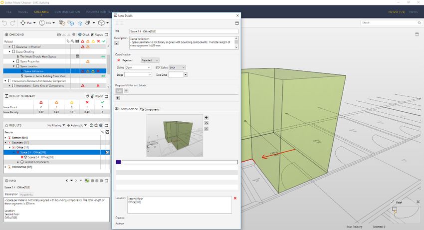
Some building code checking rules (e.g. accessibility rules) are included in the delivery.
Welcome                                                                                                   These rules are country specific, but by adjusting rule parameters they can be modified to
Thank you for choosing Solibri Model Checker™.                                                            fit many countries or jurisdictions. Please note that you may need to change space
                                                                                                          categories to fit the space names in your model.
This document is designed as a short course to guide you through the Rule-based
analysis process of Building Information Modeling (BIM) files. By the end of this tutorial,               As a result, the rule generates issues and in some cases a rule report. Issues are grouped
you will have a basic understanding of the concepts and some capabilities of the Solibri                  into categories, which makes it easier to understand and address them.
Model Checker (SMC). For additional information, we recommend reading the SMC
online documentation.                                                                                     Communicating the Results
This document is made specifically for Solibri Model Checker. If you have an earlier                      SMC’s Automatic Issue Navigator will visualize the issue in 3D by navigating to
version, please note that the user interface may have changed.                                            components causing the problem and hiding temporarily irrelevant components.

                                                                                                          When the problems are defined and visualized it is still always up to the end-user to
                                                                                                          decide which issues require action.
1. About Solibri Model Checker™
                                                                                                          You can create quite a powerful workflow by creating a slideshow presentation of items or
Solibri Model Checker™ is a software tool that analyzes Building Information Models for                   issues of interest. You can then use this "Visual Report" as a dynamic working document
integrity, quality, and physical security. Solibri Model Checker makes the QA/QC process                  for finding and determining solutions to the reported issues. A saved SMC file with results,
as easy as possible by X-raying the building model to reveal potential flaws and                          decisions, and presentations can be viewed by anyone using the Solibri Model Viewer (a
weaknesses in the design, highlighting the clashing components and checking that the                      No Charge download available at www.solibri.com.)
model complies with the building codes and organizations’ own best practices (see Figure
1).                                                                                                       Next, you can pass findings forward by creating a "Coordination Report" and sending it, for
                                                                                                          example, to the author of the model. The author can then view the report and make the
Checking the Design                                                                                       necessary changes to the original BIM file. There is also a possibility to use BCF-files.
Companies in the AECO (architectural, engineering, construction, owner/operator) field
are facing new opportunities and challenges as CAD systems are evolving from electrical                   With these steps you have analyzed the BIM file, made your expert comments,
drafting boards to BIM Authoring Tools. All the major BIM Authoring tools today are able to               documented and visualized the problems and made it easy for the BIM author to fix the
produce building models containing the relevant building components and related                           problems. By following this workflow, you have also created an audit trail without any
information, all in one file.                                                                             extra effort. This is part of the process of BIM Quality Assurance (see Figure 1).

BIM files offer huge advantages for the AECO industry, but they also introduce new
challenges. When information is exchanged and utilized in an electronic format, it is critical
that the data can be trusted.

Solibri Model Checker (SMC) enables you to check a BIM file against a set of rules and
to identify and report potential problems found. This is significantly faster and more reliable
than the traditional way of manually checking and analyzing the building documents.

Rule-based Analysis
Rules are the basic building blocks of the Solibri Model Checker. A rule can check a model
from a single aspect (e.g. spaces are aligned with surrounding walls and therefore area
measurement is giving correct values) or from some specific point of view (e.g. usage of
correct construction types). Some rules also report key characteristics (e.g. list of window
types and sizes) of a building.

                                                                                   Copyright © 2018 Solibri Oy All Rights Reserved                                                                   1
Figure 2 Registration window

                                                                                                            Defining Settings in File Layout
Figure 1 Overview of SMC QA/QC Process                                                                      1)    The main window of SMC is opened and you’ll see the File Layout (see Figure 3)

2. Installing Software
1)   Download the Solibri Model Checker from the Solibri Solution Center https://
     solution.solibri.com/ Run the executable installer file and follow installer instructions.

2)   If you have custom add-ons to Solibri Model Checker, install SMC first and then install
     the custom add-ons and follow the instructions.

Launching the Software for the First Time
1)   Double click the Solibri Model Checker icon on your desktop.

2)    ‘Welcome to Solibri Model Checker’ window opens à Insert your Username and
     password and click Register (see Figure 2)

                                                                                                            Figure 3 File Layout and “Recent Files”

                                                                                     Copyright © 2018 Solibri Oy All Rights Reserved                                                               2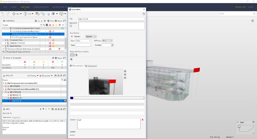
2)   Next you check your settings by Selecting Settings from the menu on the left (see                3)    Units setting, you may also want to set the Units to be used by the SMC user
     Figure 4).                                                                                             interface. You may change these units any time during your session. Please note that
                                                                                                            some rules require recalculation in order to update the rule results to use new Unit
                                                                                                            settings (see Figure 6)

Figure 4 File Layout and “Settings”

     Enter the user information into the General window and click OK (see Figure 5).

                                                                                                      Figure 6 Selection of Units

                                                                                                      Tutorial Videos
                                                                                                      You may also watch tutorial videos that are available by selecting Help from the menu and
                                                                                                      then by clicking the “Tutorial” button (see Figure 7). This will take you to the Solibri
                                                                                                      Tutorials web page.

Figure 5 Settings-> General Dialog

                                                                               Copyright © 2018 Solibri Oy All Rights Reserved                                                                 3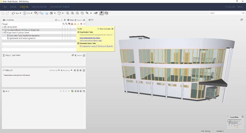
Figure 8 Open Models Dialog
Figure 7 Help-> Tutorials
                                                                                                     2)    Select SMC Building file on the bottom of the list and click Open.
Please note that the file(s) opened here may also be tailored by your organization
and in this case differ from what is shown here.                                                     3)    Model discipline, when the model is opened you will be asked to verify the discipline
                                                                                                           the model belongs to. You can also set a category for different types of files. Setting
                                                                                                           the correct discipline is paramount for the rules to work correctly, see Figure 9.

3. Visualization
Opening a Model
SMC imports BIM files in neutral IFC format. You can find more information about
additional options in the SMC Help.

Opening a Model:
1)   When you click Open Model on the left sidebar menu, you will see the Open Models
     window that shows sample files (see
     Figure 8).

                                                                                                     Figure 9 Ensuring Model Disciplines

                                                                              Copyright © 2018 Solibri Oy All Rights Reserved                                                                        4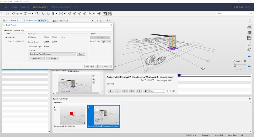
4)   After the file has been opened, you will see the model in the user interface. Note:                   Add Models: adding (merging) one or more files to the session
     You are now operating in the Model Layout View (see Figure 10).
                                                                                                           Update Models: updating existing models already opened during the session or included
                                                                                                           in the current SMC model

                                                                                                           Save Model: saving current model with the current file name

                                                                                                           Save Model as: saving current model with a new file name

                                                                                                           Security Settings: setting up security parameters like locking the file with a password or
                                                                                                           expiration date

                                                                                                           Close: closing the current model

                                                                                                           Recent: most recently used files and file locations

                                                                                                           Roles: selecting a user role

                                                                                                           Solution Center: possible extensions to SMC

                                                                                                           Settings: setting up tool parameters, user information, units, discipline and color mapping,
                                                                                                           etc.

                                                                                                           Help: help documentation and support options

                                                                                                           Ruleset Manager: consists two layouts; Ruleset Manager for modifying rule parameters
Figure 10 SMC User interface showing the Model layout                                                      and Rulesets, Extension Manager for creating Company Based Resources.

Exploring the User Interface                                                                               Please note that depending on your user profile you may not have access to
                                                                                                           Ruleset Manager. In this case contact your system administrator.
Layouts                                                                                                    Exit: closing the current model and the application
The user interface consists of five Layouts, by default. Layouts are; File, Model, Checking,
Communication, and Information Takeoff (see Figure 11). You have the possibility to add
new layouts (+) or modify the existing layouts.

Figure 11 Five main layouts are File, Model, Checking, Presentation and Information Takeoff

File Layout
The File layout includes the following headings (see Figure 12):

Open Model: opening IFC, DWG, PDF or SMC files
                                                                                    Copyright © 2018 Solibri Oy All Rights Reserved                                                                     5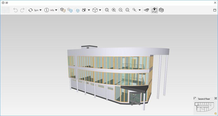
Figure 13 The Model layout

                                                                                                       Checking Layout
                                                                                                       This layout introduces the Checking View where you can work with Rules and Rulesets,
                                                                                                       the Results View where you can find the Rule Issues, and the Result Summary view
                                                                                                       which summarizes the Issues count related to a specific Rule to get an overall view of
                                                                                                       the model quality and possibility to make a QA report. (see Figure 14)

Figure 12 File Layout

Model Layout
By default you can see three views; Model Tree, Info, and 3D (see Figure 13).

The Model Tree shows the model containment hierarchy by default.

The Info View shows information of the selected component.

The 3D View shows the model in graphical format once you have opened a model.                          Figure 14 The Checking layout

                                                                                Copyright © 2018 Solibri Oy All Rights Reserved                                                                 6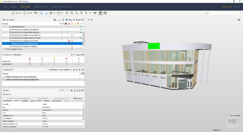
Communication Layout
This layout is for collecting and saving Rule based Issues and User definable Viewpoints
into a presentation/slideshow. This is a convenient and powerful way to show and share
the findings in the model (see Figure 15).

                                                                                                          Figure 16 The Information Takeoff layout

                                                                                                          Views
                                                                                                          By default SMC has preselected views available in four different layouts. When you want
                                                                                                          to explore more of the model information you can open additional views (see Figure 17).
Figure 15 The Communication layout

Information Takeoff Layout
This layout is for collecting information from the model. In brief, Information Takeoff
(ITO) allows users to collect information from the BIM file, organize it, visualize it, and
report it. This information can include spatial areas for area calculations, envelope of the
building (e.g. exterior wall areas) for energy calculations, volumes, quantity takeoff and
much more (see Figure 16).

                                                                                                          Figure 17 Adding views

                                                                                                          All additional views open as floating views that you can move around the active Layout.
                                                                                                          The floating view will disappear when you change to a different layout. When you get back
                                                                                                          to the layout where you opened the view it will reappear.
                                                                                   Copyright © 2018 Solibri Oy All Rights Reserved                                                                  7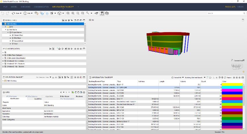
You can open, resize, dock/undock and close views. When you grab the dotted area of the
                                                                                                           View                   Contains
view at the top left-hand corner you can dock the view into the layout. A rectangle will
show where the view will be dropped. You can undock the view by selecting the menu at
                                                                                                           3D                     Graphical representation of the model.
the top right-hand corner (see Figure 18).
                                                                                                                                  Allows user to move and rotate the model and visualize it from different
                                                                                                                                  viewpoints. Allows user to select, hide and make components
                                                                                                                                  transparent.

                                                                                                           Checked                Shows information about the checking status of components: All
                                                                                                           Components             Checked, Passed, Failed, etc.

                                                                                                           Checking               Active Rulesets
                                                                                                                                  Allows user to launch checking and create reports
Figure 18. Docking a view

                                                                                                           Classification         Allows user to classify and visualize components by various
                                                                                                                                  classifications (e.g. by space usage).
You'll mainly use the 3D, Model Tree, Checking and Results Views in the following
chapters (see Figure 19). Let's take a closer look at them.                                                Compartmentation       Functionality to create and modify different compartments (gross area,
                                                                                                                                  fire, or secure compartments)

                                                                                                           Filtering              Allows user to create different filters and use them in making selections

                                                                                                           Hyperlink              Create and manage hyperlinks. Hyperlinks can be added at any level
                                                                                                           Manager                within Solibri Model Checker and to almost any element, including
                                                                                                                                  Rulesets, models, types, components, issues and slides.

                                                                                                           Info                   Shows information about selected component, rule or issue.

                                                                                                           Information            Allows user flexible collecting of information, visualization, and reporting.
                                                                                                           Takeoff                Also hyperlink connections to components can be exported with it.

                                                                                                           Model Tree             A tree view of the model

                                                                                                           Parameters             Parameters of the selected rule

Figure 19 3D view                                                                                          Communication          Shows slideshows created from the model

                                                                                                           Report                 Shows report of the selected rule, if available.
Different views allow the user to execute different actions. The main purposes are:
                                                                                                           Results                Shows results of the selected rule

                                                                                                           Results Summary        Summarizes the Issue count of a selected rule

                                                                                Copyright © 2018 Solibri Oy All Rights Reserved                                                                                   8
View Contains Visualization of the Model
You’ll select all visualization and other tools from the 3D View Toolbar (see Figure 20).
Selection Basket Shows the selected components
Space Grouping Shows user the space grouping tree of the current model
Tools Possible tools of the selected rule
Figure 20 3D view toolbar – Navigation models and actions
Try to pan and spin the model.
Walk Navigation
In the walk mode you can walk inside the building. When you click Walk (see Figure
21) the model is leveled horizontally. In the walk mode the movement is controlled by
mouse. Press and hold down the mouse button and move it around the view. The center
of the 3D View is the base point. When your mouse is above the center point, you move
forward. The distance from the center point determines the speed. Similarly, you’re your
mouse is below the center point, you move backward. When it is right of the center point,
you move to the right, etc.
Walk has a fixed “walking height” and it helps you when walking stairs and sloped slabs as
it follows the surfaces below. Collision Detection prevents you from walking through walls
and obstacles. You can turn this mode on and off by pressing the letter "c" on your
keyboard (while in walk mode). When you walk close to a door it will be hidden
temporarily. You also have the ability to walk inside the building using typical game
controls by choosing Game from the menu.
Copyright © 2018 Solibri Oy All Rights Reserved 9You may use and combine markups until you push the “Stop” button, press “Esc” key or
change to another tool.
Dimension Tool
Dimension Tool is for finding out what is the dimension between surfaces, edges or
points.
Select two objects or surfaces to measure the distance between them (see Figure 23).
Figure 21 Walk controls
You can always look at the component information when you select Info and then click
a component in the 3D View. Information of the selected component is shown in the Info
View in the lower left corner of the screen.
Markup Tool Figure 23 Dimension controls
Markup Tool is for adding markups to highlight found problems. Markups can be saved
e.g. to presentations to be sent to other parties for information. Sectioning Tool
Sectioning Tool is used to cut the building by section plane. It is also possible to move a
A markup can be for example a round shape, a line, a picture, a cloud shape. The markup plane when defined.
comes to the surface where you have pointed your mouse. You need to choose a markup
tool before making a markup (see Figure 22). Select a surface you want to use as the sectioning plane. You can have up to 6 different
sections (see Figure 24). You can move the Section plane by keeping Shift-button down
and pressing the left key on mouse or by keeping the Shift-button down and scrolling the
mouse wheel.
Figure 22 Markup Tool
Figure 24 Sectioning controls
Copyright © 2018 Solibri Oy All Rights Reserved 10Selecting Components Visible in the Model Visualization of Components on a Selected Floor
You can temporarily show and hide components in the model using the following options It is often easier to handle a model floor by floor. All building components like walls,
(see Figure 25). columns, etc. and also spaces should be contained by a building floor. Federated Floors
hierarchy can be used to see all discipline within one floor level.
Model containment hierarchy is shown in the Model Layout. Click the Model Layout tab
in the upper left corner of the SMC Window (see Figure 27).
Figure 25 3D view toolbar – Show/hide options
Zoom and Viewpoints
You can always switch the Main View to one of, Front, Back, Left, Right, Top, Bottom,
Top Front Left etc. from the small triangle on the right side of the Main Views icon.
This view will be the default and it is used when you click the Main View. You can zoom
the model also by rolling your mouse wheel. And if you keep your mouse wheel down,
you can pan the model (see Figure 26).
Figure 27 Model Tree view tab
The containment hierarchy is shown by default. You can open and close nodes in the
Model Tree by clicking the small and boxes. Open the model hierarchy and click
First Floor from the Model Tree. Then click Set to Selection Basket from the toolbar
(see Figure 28). Please consult online documentation for more advanced use of the
Selection Basket.
Figure 26 3D view toolbar – Zoom and viewpoints
Copyright © 2018 Solibri Oy All Rights Reserved 11You can show all components by clicking the Show All . And if you want to see only
the selected components (floor) again, click Show Selected Only .
4. Checking & Analyzing a Model/Design
Choosing a Role
Role is a collection of Rulesets and other resources that are tailored for a given purpose.
At the Checking layout, before you can proceed with the checking process, you are
prompted to choose a Role. Once you have chosen a Role, you will go directly to
‘Opening/Adding Ruleset’ phase.
When selecting the “Training” Role (see Figure 30) you will have the getting started
Ruleset already selected and you can move to the next phase “Checking the Design”.
Figure 28 Model Tree view
Only the selected floor is shown in the 3D View (see Figure 29). Tilt the building so you
can see it from the plan view (or click Top from the Main Views menu).
Figure 30 Choose a Role window
Opening/Adding a Ruleset
After choosing your Role, you get a dialog with a list of Rulesets to choose from. Also, you
find a (+Add Rulesets) tab to browse and add more Rulesets (see Figure 31).
Figure 29 First floor is shown in the 3D view
NOTE. USE THE Getting started RULESET ONLY FOR TRAINING!
You can select multiple floors at once by holding the Ctrl-button down. Or you can add
floors to the selection by using the Add to Selection Basket . Selected components
can be seen in the 3D View and also in the Selection Basket View.
Copyright © 2018 Solibri Oy All Rights Reserved 12The To-Do list
Before you can proceed to the checking process, SMC will present you with a To-Do list of
tasks (Completing of Classifications, filling in of project specific parameters, etc.) to be
performed in order to get reliable results when checking your model or running ITOs (See
Figure 33).
Figure 31 Select a Ruleset window
You can also open and add more Rulesets in the Checking view in the following way:
Each Ruleset is a file with .cset extension. All Rulesets are installed on your computer in
the Rulesets folder or as shared resources on a centralized location on your
network. You can edit current Rulesets and create new ones in the Ruleset Manager
(read more about this in our online documentation).
Figure 33 The To-Do list
Please note that depending on your user profile you may not have access to
Ruleset Manager or you may not have the possibility to modify the rule parameters Example 1: Classification Task
or Rulesets. In this case contact your system administrator. An example of a To-Do list with Classification tasks to be performed (Figure 33), selecting
‘Verify classification ‘Building Elements – General’ ‘classification’ will open the Missing
Click the Click to add Ruleset … or click Add in the Checking View Toolbar (see Classification dialog window (see Figure 34).
Figure 32). Select Ruleset dialog is opened. You can select more Rulesets to add. In this
tutorial we don’t have to add more rulesets.
Figure 32 Add Ruleset
Once the Ruleset is imported, it is shown in the Checking View.
Copyright © 2018 Solibri Oy All Rights Reserved 13Figure 34 Missing Classification dialog windows
Figure 36 Required Classification Tasks are completed
In the window, pressing the Open Classification Settings tab will open the Classification
Settings dialog window (see Figure 35). Your task is to ensure that all the necessary When this task is completed, the Classification and the task is greyed in the To-Do list
components are classified in order to run checking rules using classification names. notifying you that it is done and you can continue with the next task (see Figure 37)
Example 2: Data Import Task
Another example of a To-Do list with tasks to be performed is the task Fill in parameter
values of ‘Construction Types Must Be from Agreed List’. Clicking on the task will open ‘Fill
parameter values’ dialog (see Figure 37).
Figure 35 Classification Setting dialog window
Figure 37 Fill parameter values dialog
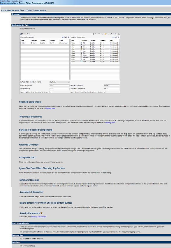
Copyright © 2018 Solibri Oy All Rights Reserved 14Parameters of the rule can be filled manually by adding rows to the ‘Allowed Property
Values’ table, or they can be imported from a spreadsheet file (.xls or .xlsx file). Select
‘Import Excel Worksheet’ from the above right corner of the table (see Figure 38).
Figure 39 Import Excel sheet dialog window
Select the SMC Building Construction Types -> Open -> Import Excel sheet. Follow
comments in the top of the table, and select all rows but the first one (see Figure 40), and
Finish importing.
Figure 38 Rule parameters of rule ’Constructions Types Must Be from Agreed List’
Figure 40 Example task in To-Do list à Import Excel sheet
Copyright © 2018 Solibri Oy All Rights Reserved 15Values from the spreadsheet are imported to rule table parameter. You can now close the
Parameters View if you like. Once the task has been performed, it is greyed in the To-Do
list notifying you that it is done and you can continue with the next task.
Figure 38 Checking process
(3) During the checking process you can expand or close the rule tree and start
analyzing the results that are generated.
(4) Once the model is checked, the Checking Tree Table (see figure 43) shows the
Figure 41 Values imported to rule table status of each rule. The status may be (accepted, decision made that some
issues required no actions), (passed), or (irrelevant or ignored, in case the
Next you can import allowed space names from the file ‘SMC Building allowed space BIM file does not have information the rule needs), (rejected, decision made
names.xls’. Or, you can fill in the table parameter manually. some issues must be fixed) or it has a problems classified as Critical ,
Moderate , or Low Severity .
Checking the Design
Now that you have imported a model, selected a Role, opened a Ruleset(s) and
performed the tasks in the To-Do list, you are ready to check the model.
(1) Click the in the Checking View Toolbar.
(2) The checking process starts and you can follow the progress in the Checking
Tree Table (see Figure 42).
Copyright © 2018 Solibri Oy All Rights Reserved 16Figure 39 Checking tree table Example 1: Deficiency Detection
Solibri Model Checker includes Rulesets dedicated to finding what is missing from the BIM
(5) Filter results by focusing on Critical Issues (see Figure 44). file. Here are the steps to follow for this example:
(1) Make sure you have Critical , Moderate , and Low Severity level issues
visible.
(2) Open the Deficiency Detection branch by clicking the small sign next to the
Ruleset name in the Checking Tree Table.
(3) Select the Find Missing Components Below Walls rule.
(4) Info View will inform you about the nature of the rule (see Figure 46).
Figure 40 Filtering results
You can focus only on Critical issues by hiding the Moderate and Low Severity
issues by clicking their icons as shown in (see Figure 45). Clicking again on Moderate
and Low Severity to show all results.
Figure 46 Info view
(5) From the Info View click "Rule Help" and you will find the documentation related
to this rule (see Figure 47).
Figure 41 Moderate and low severity issues hidden
Analyzing the Results
As an SMC user, one of your main tasks will be analyzing the checking results, and this
task can be very different depending on the scenario at hand. Instead of going through all
the details, we will demonstrate some of the features by using examples.
Copyright © 2018 Solibri Oy All Rights Reserved 17below partially” as shown in Figure 48. Numbers in the square brackets are:
[number of decisions made / number of issues].
Figure 48 Result Summary view and Results view
(8) View components, when you click category "Wall Components touch below
partially”, only components attached to issues of the category, are shown in 3D
View. The footprints of the related building floors are also shown for easy
visualization (see Figure 49), please note the adjustable Navigation Map at the
bottom right corner.
Figure 42 Rule documentation
(6) Result Summary view and Results View. In the Result Summary view, “Issue
Count” shows the total number of issues detected from checking Rule ‘Find
Missing Components Below Walls’ according to each issue severity (see Figure
48). The “Issue Density” (issues/1000m3) gives a general understanding of
model quality.
(7) To View categories of issues, click the Results View. The issues are all in two
Figure 49 Components attached to issue are shown
categories: "Wall Components don’t touch below" and "Wall Components touch
Copyright © 2018 Solibri Oy All Rights Reserved 18(9) View list of components relating to an issue, when you select one of the issues in
the category, only components attached to the issue are shown (see Figure 50).
Please also note that if you double click the category or issue you will be zoomed
closer to related components (see Figure 51).
Figure 50 Detailed Results
Figure 52 Transparent visualization
(12) Creating a Section Box. Select one of the issues or categories, click right your
mouse, and choose Section Box in Results View popup menu (see Figure 53).
Now a section box around the problematic components is created (see Figure
54).
Figure 51 Detailed Results zoomed in 3D
(10) In case you want to visualize results differently you have several options:
(11) Transparent visualization, select one of the issues or categories, and choose
Transparent visualization in the Results View Toolbar . Now the
components in the selected issues are highlighted (see Figure 52).
Copyright © 2018 Solibri Oy All Rights Reserved 19(14) In the Issue Details view you can give the Issue a name in the Title -field and
describe it in the Description -field (see Figure 55).
Figure 53 popup menu
Figure 43 Issue Details window
(15) You will also assign the issue to a specialist to solve the problem, click on the
Responsibilities icon to activate a discipline, team, or add a new one from the +
icon. Select “Assigned” in the Status bar and assign to a team or person. (see
Figure 56).
(16) You will notice that the Results Tree now marks for existing comments and has a
red cross as this issue is now "Rejected".
Figure 54 Section Box
(13) Commenting on an Issue, Select the issue, with Wall 1.18. Click the column to
the right of the issue. You will have an Issue Details pop-up window appearing.
You can also select the issue, right-click and select ‘Add Slide’. Notice that by
default you will "Reject" this issue meaning that someone needs to fix this
problem according to the instructions you type in the "Comment" field.
Copyright © 2018 Solibri Oy All Rights Reserved 20Figure 45 Accepting issues
(18) Repeat the same procedure for other issues. Note that you can also add a slide
on a category or subcategory level. You can close the view and move on to a
new issue.
(19) Full 3D View, last step for this rule example is to show the whole building in the
3D View. Click Show All in the 3D View Toolbar. This will remove the
transparency and highlights from the 3D View. Next click Top Front Right in the
3D View Toolbar.
(20) Set Automatic navigation back on.
Example 2: Clearance in Front of
Here are the steps to follow for this example:
(1) Open the "Clearance in Front of" branch in the Checking Tree Table and also
the next level “Clearance in Front of Windows” (see Figure 58).
Figure 44 Coordination panel in Issue Details window
(17) Right click the “Wall Components don’t touch below” -> “IW-5 30”> and you will
get a pop-up window with other ways to mark the results. Choose "Mark as
Accepted" this time (see Figure 57).
Copyright © 2018 Solibri Oy All Rights Reserved 21Figure 58 Clearance in Front of Windows rule
(2) Be sure that Automatic visualization is set back on and open the “Suspended
Ceiling too Close to Window Component” category in the Results Tree Table Figure 60 Suspended ceiling in front of windows
and select the issue group “FS-3 too close to window 17 component” (see Figure
59). (4) Make a comment “Consider making the window lower to avoid suspended ceiling
being seen through the window”.
(5) Notice that other issues under “Clearance in Front of Windows” show columns,
walls and windows in front of windows but in this case, this is an architectural
feature designed this way and is not considered as a problem. Accept other
issues
Example 3: Validate Space Area and Volume
Here are the steps to follow for this example:
(1) Open the "Space Checking" -> "Space Location" branch in the Checking Tree
Table.
Figure 59 Ceiling too close to windows (2) Select the "Space Validation" rule.
(3) You can see a suspended ceiling component in front of two windows. There is a (3) Open the “Boundary” category in the Results Tree Table and select the issue
shadow showing dimensions of how much free space was required and how inside it "Boundary"-> "Office "-> "Space 2.4" (see Figure 61).
close the obstacle is (see Figure 60).
Copyright © 2018 Solibri Oy All Rights Reserved 22Figure 62 Part of the Space Boundary is not aligned with walls
(5) Right click the issue and choose “Add Slide…” from the pop-up menu. In the
Issue Details window add a comment to the description field “Space boundary is
not aligned with bounding walls”. Also, click the Coordination tab to assign the
Issue to a specialist such as “Arc”, click Ok (see Figure 63).
Figure 61 Boundary problem with Space 2.3: Office [308]
(4) In the 3D View you can see a space object and a red line showing the part of the
space boundary (see Figure 62), which is not near a wall (or another space).
Copyright © 2018 Solibri Oy All Rights Reserved 23Figure 64 The issue, intersection checking
5) Double-click the issue and you will be zoomed close to the walls causing the problem.
If you feel that you are too close, click the Zoom Out button from the 3D View
Figure 63 Issue Details Toolbar (see Figure 65).
Example 4: Checking Interferences
Here are the steps to follow for this example:
1) Open the "Intersections between Architectural Components” branch in the Checking
Tree Table.
2) Select the “Intersections -Same Kind of Components” and then "Wall - Wall
intersections" rule in the Ruleset Tree Table.
3) Open the category “Components Inside Each Other” in the Results Tree Table and
select the issue inside it. You can see two walls in the upper left corner of the building.
4) Select the "Wall.3.14 (EW-1) and Wall.3.7 (EW-1) are inside each other" from the
Results Table Tree. The smaller wall (being inside) is already rejected automatically
by the rule (see Figure 64).
Figure 65 A wall inside another wall
Copyright © 2018 Solibri Oy All Rights Reserved 243) A new presentation will be created. The slides you added in checking appear on the
5. Communication issue list, and in sorter. The first of the list will be visualized on 3D view and in Issue
details view and notice how the 3D View changes to show the stored viewpoint.
Generation of a Presentation and Coordination Report
Once you have checked a building model and saved viewpoints of the problematic
situations, you can create a slideshow to present the situation to your design or project
team.
To create a presentation switch to Communication Layout:
There are four views in communication layout: Presentations: list of presentations
Issues: list of issues in active presentation
Issue details: contains comments, coordination, decision, location etc. Of each issue
Issue sorter: the table of thumbnails where you can organize and arrange slides in one
presentation or between different presentations with drag and drop system.
1) Click the line "Click to add New Presentation…" (see Figure 66).
Figure 67 Communication View
Presenting the Slideshow
4) To show the presentation in "Full Screen Mode" you click Toggle Presentation mode
in the presentation menu below the 3D Window (see Figure 68).
The 3D View will be maximized and you have control buttons under the actual 3D
Area (see Figure 69).
Figure 66 Converting Results to Presentation
2) Type a new name for the presentation and choose presentation to be made from the
"Getting Started" Ruleset. Click OK. Figure 68 Presentation view detail
Copyright © 2018 Solibri Oy All Rights Reserved 25Creating a Coordination Report
Once you have your presentation ready you can generate a Coordination Report.
6) You can write a report containing all issues and comments by clicking Report on
the Presentation View Toolbar (see Figure 71). Create Report Dialog is opened.
Figure 69 Presentation view controls
Custom Made Issues
5) You may also add issues separately by setting a view you want to store in the 3D
View and then click "New Issue" on the Presentation Toolbar, or you can start a new
Presentation. (see Figure 70).
Figure 46 Making a Coordination Report
7) You can change the report file name and folder if you want to. Click OK.
8) After the report is written, it is generated and opened automatically (see Figure 72).
The report contains all selected issues, user comments and snapshots. Numbers
refer to numbers in the presentation stored with the SMC file. Each issue will also be
assigned a unique identification number. Once resolved, this number is not re-used.
Figure 70 Presentation toolbar
Copyright © 2018 Solibri Oy All Rights Reserved 26Figure 47 Coordination Report
Solibri Model Viewer
One good option for communicating results is to save an SMC file with presentations, user
decisions, and snapshots and then share this file with the team. With the free Solibri Model
Viewer, downloadable at www.solibri.com, anyone can view, share, and discuss these
results.
You can comment issues in the Presentation view in Solibri Model Viewer. A report is
saved in BCF-format. You can update the original model in Solibri Model Checker. That
way the comments will be updated to the presentation.
6. Getting More Information
For additional information, consult the SMC Help or visit the Solibri Customer Support
pages at www.solibri.com.
Copyright © 2018 Solibri Oy All Rights Reserved 27You can also read