Energy & Environmental Science - NESEL
←
→
Page content transcription
If your browser does not render page correctly, please read the page content below
View Article Online

Energy &
                                                                                                                                                       View Journal

Environmental
Science
Accepted Manuscript

   This article can be cited before page numbers have been issued, to do this please use: C. Ma, B. Kim, S.
   Kim and N. Park, Energy Environ. Sci., 2021, DOI: 10.1039/D0EE03487H.
                                                                                 Volume 11
                                                                                 Number 4
                                                                                                  This is an Accepted Manuscript, which has been through the
    Energy &
                                                                                 April 2018
                                                                                 Pages 719-1000
                                                                                                  Royal Society of Chemistry peer review process and has been
    Environmental                                                                                 accepted for publication.
    Science
    rsc.li/ees
                                                                                                  Accepted Manuscripts are published online shortly after acceptance,
                                                                                                  before technical editing, formatting and proof reading. Using this free
                                                                                                  service, authors can make their results available to the community, in
                                                                                                  citable form, before we publish the edited article. We will replace this
                                                                                                  Accepted Manuscript with the edited and formatted Advance Article as
                                                                                                  soon as it is available.

                                                                                                  You can find more information about Accepted Manuscripts in the
                                                                                                  Information for Authors.

                                                                                                  Please note that technical editing may introduce minor changes to the
                                                                                                  text and/or graphics, which may alter content. The journal’s standard
                 ISSN 1754-5706                                                                   Terms & Conditions and the Ethical guidelines still apply. In no event
                 REVIEW ARTICLE
                 Yuekun Lai, Zhiqun Lin et al.
                 Graphene aerogels for efficient energy storage and conversion
                                                                                                  shall the Royal Society of Chemistry be held responsible for any errors
                                                                                                  or omissions in this Accepted Manuscript or any consequences arising
                                                                                                  from the use of any information it contains.

                                                                                                                                                              rsc.li/ees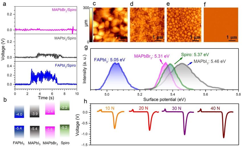
Page 1 of 8                                                                                         Energy & Environmental Science
                                                                                                                                                                                             View Article Online
                                                                                                                                                                                    DOI: 10.1039/D0EE03487H

                                                                                               Broader Context

                                                                                                                                                                                                                   Energy & Environmental Science Accepted Manuscript
                                                                                               Harvesting environmental energy to generate electricity is a key scientific development of our time.

                                                                                               Photovoltaic conversion and electromechanical transduction are two common energy-harvesting
Published on 05 January 2021. Downloaded by Sungkyunkwan University on 1/11/2021 8:17:51 AM.

                                                                                               methods, which have drawn much attention. Organic−inorganic halide perovskite materials

                                                                                               represent a recent key development in the photovoltaic field, which is attributed to their solution

                                                                                               processability and excellent photovoltaic properties. Though static perovskite PN junctions have

                                                                                               been widely studied and exploited in the photovoltaic field, the dynamic perovskite heterojunction

                                                                                               has not been studied yet. More importantly, achieving the photovoltaic effect with mechanical

                                                                                               energy harvesting in a single device is still challenging (i.e. alternative current (AC) for

                                                                                               electromechanical transduction and direct current (DC) for photovoltaic conversion). Here, we

                                                                                               demonstrate DC power from the dynamic perovskite/charge transport layer (CTL) heterojunctions

                                                                                               via electrical carrier generation from triboelectrification between two layers, which is different

                                                                                               from the electric energy generation by photon excitation in solar cells. More importantly, 1-sun

                                                                                               illumination stimulates charge carrier concentration, which results in several hundred times higher

                                                                                               current output than that in the dark due to the coupling triboelectric and photovoltaic effects. These

                                                                                               findings open a new research area of triboelectric naonogenerator generating DC power.
Please&do
Energy not adjust margins
Environmental Science Page 2 of 8
View Article Online
Journal Name DOI: 10.1039/D0EE03487H
Energy & Environmental Science Accepted Manuscript
ARTICLE
Dynamic halide perovskite heterojunction generates direct current
Chunqing Ma,aǂ Bosung Kim,bǂ Sang-Woo Kim,b* Nam-Gyu Parka*
Published on 05 January 2021. Downloaded by Sungkyunkwan University on 1/11/2021 8:17:51 AM.
Received 00th January 20xx,
Accepted 00th January 20xx Here, we demonstrate a dynamic perovskite device capable of converting mechanical energy into direct current (DC)
electrical energy, combining two concepts: carrier generation from triboelectric effect and carrier separation through band
DOI: 10.1039/x0xx00000x energy level difference. By analyzing and comparing different perovskite (FAPbI3, MAPbI3, MAPbBr3, PEA2PbI4, etc.) and
charge transport layer (CTL) materials (spiro-MeOTAD, PTAA, TiO2, SnO2, etc.), the key rules for determining DC output and
www.rsc.org/
performances are identified: (1) a suitable band alignment (band position and bandgap) between perovskite and CTL can
separate the carrier transfer; (2) a large difference in work function between two layers leads to high electrical potential
difference; and (3) a high carrier concentration can enhance the DC power-generating performances. Furthermore, it is
found that the light illumination acts as a stimulus to current output to a large extent, which is due to the coupling effect
from triboelectric and photovoltaic effects. This study provides a set of key rules to explain the mechanism and to further
improve the performance of the dynamic perovskite/CTL heterojunction.
Introduction triboelectric processes and the carrier directional transfer at static
perovskite/CTL heterojunctions, we hypothesized that DC power
Harvesting energy from nature is a key scientific and technological generation could be achieved in response to applied mechanical
concept.1-2 Among different environmental energies, conversion of energy through a dynamic perovskite/CTL heterojunction.
solar energy and mechanical energy to electric power is invaluable Static perovskite/CTL heterojunctions have been widely studied and
and thereby those technologies have drawn much attention.3-5 exploited in solar cells.26-27 Here, we demonstrate for the first time
Organic−inorganic halide perovskite materials have shown great that DC power can be generated at dynamic perovskite/CTL
potential in photovoltaic field since seminal works by Miyasaka et heterojunctions by electrical carrier generation from
al. and Park et al.6-8 In these devices, the perovskite layer acts as a triboelectrification between two layers, which is different from the
light absorber and generates free carriers under light illumination, electric energy generation by photon excitation in solar cells. Key
after which the free carriers are separated by the different charge factors for determining the DC output and performances (i.e.
transporting layers (CTL) due to the different bandgap alignments.9- voltage and current) are studied: (1) heterojunctions formed by
12 materials with different band energy levels; (2) work function
There also has been parallel progress in electromechanical difference between the two sliding materials and (3) carrier
properties of organic−inorganic halide perovskite (piezoelectric, concentrations and mobilities. In these dynamic perovskite/CTL
triboelectric, and photoflexoelectric properties, etc.).13-17 Using the devices, carriers in the heterojunction are separated during the
triboelectric device as an example, contact electrification can movement, as confirmed by photoluminescence (PL) and time-
provide the polarized charges on material surfaces and electrostatic resolved PL (TRPL) measurements. As a result, free electrons and
induction can drive the charges to flow between two electrodes via holes generated by triboelectrification from the sliding motion can
changes in electric potential. Most of the triboelectric or be directionally transferred by the heterojunction, forming DC
piezoelectric devices can only produce alternative current (AC) power output. Furthermore, more electrons and holes are
outputs with the changed contact status. A rectifier is needed to generated by photovoltaic effects under 1-sun illumination.
convert AC to direct current (DC), which not only reduces the Combining the triboelectric and photovoltaic effects, the current of
energy conversion efficiency but also increases the device size. It a dynamic device under 1-sun illumination is about several hundred
was also reported that DC output can be achieved by the dynamic times higher than that in the dark. This new device can be used as a
Schottky and PN junctions (i.e. polymer/metal, inorganic/metal multi-energy (mechanical and solar energy) input system for self-
junctions) due to the directional carrier transfer between two powered electronic devices, such as portable electronics, wearable
materials.18-25 Inspired by the electric generation based on electronics, self-powered sensors, e-skin, and sustainable devices.
Results and discussion
a. School of Chemical Engineering, Sungkyunkwan University, Suwon 16419,
Korea, E-mail: npark@skku.edu Perovskite used here is FAPbI3 (FA = formamidinium) with MACl
b. School of Advanced Materials Science and Engineering, Sungkyunkwan (MA = methylammonium) as an additive to improve the quality and
University, Suwon 16419, Korea, E-mail: kimsw1@skku.edu
c. ǂ These authors contributed equally to the work
stability.28 Structure and morphology of the perovskite film were
Electronic Supplementary Information (ESI) available. See characterized by X-ray diffraction (XRD) and scanning electron
DOI: 10.1039/x0xx00000x microscopy (SEM). As shown in Figure S1a and b, the perovskite
This journal is © The Royal Society of Chemistry 20xx J. Name., 2013, 00, 1-3 | 1
Please do not adjust margins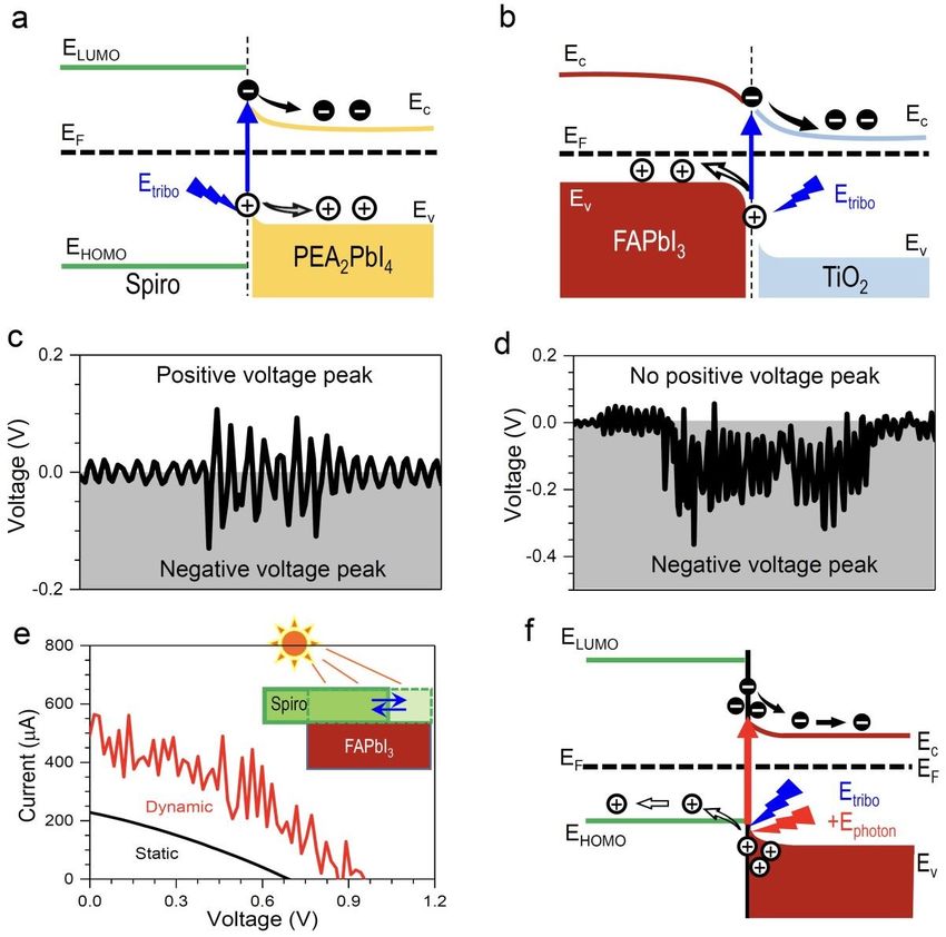
Page 3 of 8 Please&do
Energy not adjust margins
Environmental Science
ARTICLE Journal Name
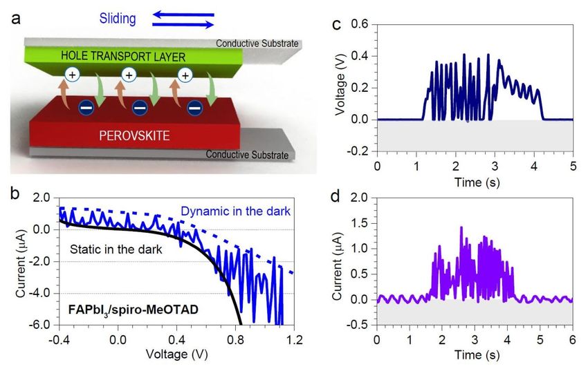
film shows a pure phase with uniform grain size and good coverage. shown in Figure 1a, the current and voltage are View measured by
Article Online
Moreover, the absorption and PL spectrum in Figure S1c show that pressing the spiro-coated electrode to make contact with the
DOI: 10.1039/D0EE03487H
the perovskite has a bandgap of ~1.5 eV. The dark current-voltage perovskite-coated electrode and sliding the spiro film on the
(IV) curve was measured by pressing the 2,2′,7,7′-tetrakis (N, N -di- perovskite surface. The IV curve of the device under the movement
Energy & Environmental Science Accepted Manuscript
p -methoxyphenyl-amine)9,9′-spirobifluorene (spiro-MeOTAD, for is shown in Figure 1b. The fluctuation of the IV curve under
short spiro) on the surface of the perovskite film to ensure the movement compared with the static condition is indicative of the
electric contact. As shown in Figure S2, the static perovskite/spiro voltage and current output.20 As shown in Figure 1c and d, a DC
heterojunction shows a nonlinear curve with a rectifying effect, voltage of ~0.4 V and a current of ~1.2 A are achieved, which is
which is attributed to the formation of heterojunction.29 The consistent with the results from the IV curve. This DC power is
performance of the dynamic perovskite/CTL junctions below are all assumed to be related to the band alignment between perovskite
measured in the dark if without further notification. and spiro, which can directionally transfer carriers.
The electric power output of the dynamic perovskite/spiro
heterojunction was studied based on the sliding contact mode.30 As
Published on 05 January 2021. Downloaded by Sungkyunkwan University on 1/11/2021 8:17:51 AM.
Figure 1. Schematic device structure and output analysis. (a) Schematic illustration of the dynamic perovskite/hole transport layer (HTL)
heterojunction device. (b) IV curves obtained from the dynamic sliding contact between the FAPbI3 perovskite and the spiro layers, along
with static (no sliding movement) condition, measured in the dark (c) voltage and (d) current output of the dynamic perovskite/spiro
heterojunction device under continuous sliding movements. The contact area was ~1 cm2 and the applied force was ~5 N.
To study the mechanism of carrier generation and transfer at the on the surface and much slower component (τ2) is due to radiative
dynamic perovskite/spiro heterojunction, the Mott-Schottky, recombination of carriers in the bulk.39-40 Under the bending
steady-state PL, and TRPL measurements were conducted on the condition, the slow decay component (τ2) is slightly decreased from
perovskite/spiro heterojunction. As shown in Figure 2a, the Mott- 87 ns (static) to 81 ns (bending), while τ1 is significantly reduced
Schottky curve shows a built-in potential of 0.38 V for the static from 27 ns (static) to 16 ns (bending), which supports that the
perovskite/spiro junction, which confirms the formation of a stable friction induced by the bending can facilitate carrier separation and
PN junction. To study the carrier dynamic of the perovskite/spiro enhance carrier transferring at the perovskite/spiro interface.
junction, the PL and TRPL spectra of the device (see details in
experimental section) were measured under static and bending Based on the above analysis, we interpret the DC power generation
conditions. Figure 2b shows that the PL intensity of the device in dynamic perovskite/spiro heterojunctions through the following
reduces from ~ 27000 counts under static to ~ 22000 counts under possible processes: (1) Figure 2d shows the energy band levels of
bending, which is indicative of enhancement in carrier separation perovskite and spiro materials before the two layers come into
and transfer between perovskite and spiro.37 TRPL data in Figure 2c contact. Perovskite is supposed to be n-type and spiro is a p-type
are fit with a bi-exponential decay equation, where relatively fast material. (2) When the perovskite contacts with spiro at a static
decay component (τ1) is assigned to carrier transfer or separation condition, the electrons in the n-type perovskite are attracted to
2 | J. Name., 2012, 00, 1-3 This journal is © The Royal Society of Chemistry 20xx
Please do not adjust margins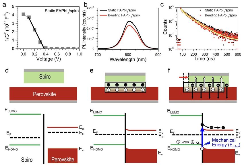
Please&do
Energy not adjust margins
Environmental Science Page 4 of 8
Journal Name ARTICLE
the positive holes in the p-type spiro and they diffuse into the p- (3) When the top material is sliding, free chargeView carriers are
Article Online
type materials. Similarly, the positive holes in the spiro are generated by triboelectric effects. Then, theDOI:
electrons and holes can
10.1039/D0EE03487H
attracted and diffuse to the perovskite. As a result, an electrical be directionally transferred to perovskite and spiro, respectively,
potential is formed between two materials, as shown in Figure 2e. forming a DC power (Figure 2f).
Energy & Environmental Science Accepted Manuscript
Published on 05 January 2021. Downloaded by Sungkyunkwan University on 1/11/2021 8:17:51 AM.
Figure 2. Mechanism of the dynamic perovskite/CTL heterojunction. (a) Mott-Schottky curve of the static perovskite/spiro junction. (b) PL
and (c) TRPL of the perovskite/spiro heterojunction under static and bending conditions (solid lines represent the fit results based on bi-
exponential decay equation). (d) and (e) Schematics and energy band diagram of the perovskite/spiro heterojunction before and after
contact (static heterojunction). (f) Free charge generation by triboelectric effects and the directional charge transfer by mechanical energy
(triboelectric potential).
To explore the factors that determine the voltage and current
To study the voltage and current performances, perovskites with performances, piezoelectric force microscope, kelvin probe force
different band levels and electronic properties (i.e. FAPbI3, MAPbI3, microscope, Hall effect measurements were conducted on these
and MAPbBr3) were applied in the dynamic heterojunction with samples. As shown in Figure S6, although FAPbI3 shows a larger
spiro. Structure and thickness of FAPbI3, MAPbI3, and MAPbBr3 piezoresponse value compared to MAPbI3, and MAPbBr3 in d33
were studied by XRD (Figure S3) and SEM (Figure S4), where the direction, it is a very small value compared to the reference (Al2O3)
thickness of ca. 560 nm is observed for FAPbI3 and MAPbI3. As sample indicating that the DC power-generating performance is
shown in Figure 3a, the device based on FAPbI3 shows the highest hard to be determined by the piezoelectric property of the
voltage of 0.4 V, while the MAPbI3 and MAPbBr3 show reduced perovskites. The topography images of FAPbI3, MAPbI3, MAPbBr3,
voltages of 0.05, and ~0 V, respectively. The current of the FAPbI3 and spiro are shown in Figure 3c-f, which shows uniform films with
(~1.2 A, Figure 1b) is also higher than the MAPbI3 (~0.6 A) and good coverage. As shown in Figure 3g and Figure S7, the work
the MAPbBr3 (~0.2 A), as shown in Figure S5. The band energy function, determined by surface potential, of FAPbI3, MAPbI3,
levels of the FAPbI3, MAPbI3, MAPbBr3, and spiro are shown in MAPbBr3, and spiro are 5.05, 5.46, 5.31, and 5.37 eV, respectively. It
Figure 3b.36 Interestingly, though the FAPbI3 and MAPbI3 have should be mentioned that the work function difference between
similar VB and CB levels, the voltage and current performances of FAPbI3/spiro (0.32 eV) is larger than that of MAPbI3/spiro (0.09 eV)
the FAPbI3 device are about 8 and 2 times higher than the device and MAPbBr3/Spiro (0.06 eV), which proves a higher driving force
based on MAPbI3, respectively. This result is different from the for carrier transfer between FAPbI3 and Spiro than that between
perovskite solar cells, in which the band energy levels play a key MAPbI3 or MAPbBr3 and spiro. Therefore, we attribute the large
role in the carrier transfer between perovskite and CTL. In the voltage performance in the FAPbI3/spiro device to the large work
dynamic device, the carrier generation and separation processes function difference between FAPbI3 and spiro, while the devices
are dominated by the triboelectric effect at the interface. Thus, the based on MAPbI3 and MAPbBr3 show significantly reduced voltages
band energy level is not the key point to control the voltage and because of the small work function differences with spiro.37 The
current performances. electronic properties of these perovskites are studied by Hall effect
and summarized in Table 1. The FAPbI3, MAPbI3, and MAPbBr3 show
This journal is © The Royal Society of Chemistry 20xx J. Name., 2013, 00, 1-3 | 3
Please do not adjust marginsPage 5 of 8 Please&do
Energy not adjust margins
Environmental Science
ARTICLE Journal Name
similar Hall mobilities, while the carrier concentrations of FAPbI3 MAPbI3 4.8 6.4
View Article Online
and MAPbI3 are 3 and 10 times higher than that of MAPbBr3, MAPbBr3 0.44 6.2
DOI: 10.1039/D0EE03487H
respectively. Thus, the high carrier concentration can also PEA2PbI4 1.5 0.8
contribute to the high voltage and current performances. It should
Energy & Environmental Science Accepted Manuscript
be noted that the voltage and the current for MAPbI3 are low Spiro films with different areas were used to study the effect of
although MAPbI3 has a higher carrier concentration and mobility contact area on the voltage and current performances. As shown in
than FAPbI3. We attribute this to the small work function difference Figure S8, with the contact area increasing from 0.3, 0.6, and to 1
between MAPbI3 and spiro, which results in the low carrier cm2, the current generated from the perovskite/spiro
separation at the interface. heterojunction increases from 0.6, 0.9 to 1.2 A, while the voltage
is hardly influenced. Furthermore, different applied forces were
Table 1. Carrier concentration and Hall mobility of FAPbI3, MAPbI3, also applied to the dynamic perovskite/spiro heterojunction. As
MAPbBr3, and PEA2PbI4. shown in Figure 3h, in the applied force ranging from 10 to 40 N,
Materials Carrier concentration Hall mobility the voltage increases with the applied force on the dynamic device,
Published on 05 January 2021. Downloaded by Sungkyunkwan University on 1/11/2021 8:17:51 AM.
(1016 m-3) (10-2 m2/V s) and the highest voltage of 1.3 V can be achieved under 40 N. The
FAPbI3 1.5 5.5 current also slightly increases with the applied force, as shown in
Figure S9.
Figure 3. Parameters affecting triboelectric voltage. (a) Voltage performance of FAPbI3, MAPbI3, and MAPbBr3 with spiro. The contact area
was ~1 cm2 and the applied force was ~5 N. (b) Schematic illustration of band energy levels of FAPbI3, MAPbI3, MAPbBr3, and spiro. (c to f)
Topography images and (g) work functions of FAPbI3, MAPbI3, MAPbBr3, and spiro. (h) Dependence of voltage output on applied force on
the dynamic FAPbI3/spiro heterojunction.
To reveal the relationship for the DC power generation caused by lower than those of spiro, which forms a Type II alignment.34 Thus,
the directional carrier transfer and band alignments, tunable the electrons will transfer to that of FAPbI3, while the holes will
heterojunction architectures between perovskite and electron spontaneously transfer to that of spiro. Unlike the Type I alignment,
transport layer (ETL) or HTL were studied. The detailed relationship the Type II heterojunction shows separated electron and hole
between triboelectric voltage output and heterojunction transfer routes.35 Thus, a DC power is observed (see Figure 1c). To
architectures are shown in Figure 4. As shown in Figure 4a, the CB further confirm the directional carrier transport by the band
of PEA2PbI4 (PEA = penylethylammonium) two-dimensional (2D) alignment, Type II alignment between TiO2 ETL and FAPbI3 was
perovskite is lower than that of spiro, and its VB position is above studied, as shown in Figure 4b. In this TiO2/FAPbI3 junction, the
that of spiro, which exhibits Type I alignment.31-33 When the electric electrons will transfer to TiO2 and holes will transfer to FAPbI3,
energy generated by the triboelectric effect, electrons, and holes on which is opposite to that of the FAPbI3/spiro heterojunction. As
the contact surface will transfer to 2D perovskite in the same expected, a negative DC output is observed, as shown in Figure 4d
direction driven by the band energy difference. As a result, an AC and Figure S11. Based on these analysis of band alignments, we
power is observed in Figure 4c and Figure S10, which is due to the conclude that the DC power is due to the directional carrier transfer
unseparated electron and hole transfer routes. For the FAPbI3/spiro by the band alignment.
heterojunction (see Figure 2f), the CB and VB levels of FAPbI3 are all
4 | J. Name., 2012, 00, 1-3 This journal is © The Royal Society of Chemistry 20xx
Please do not adjust marginsPlease&do
Energy not adjust margins
Environmental Science Page 6 of 8
Journal Name ARTICLE
As the perovskite is an excellent photovoltaic material, the observed for spiro films, where a thickness of 200 nm shows the
View Article Online
influence of the photovoltaic effect on the energy output from the highest performance. DOI: 10.1039/D0EE03487H
triboelectric effect was studied. The IV curve for the static and
dynamic device under 1 sun (100 mW cm-2) illumination is shown in The stability of the dynamic device is studied. The SEM image
Energy & Environmental Science Accepted Manuscript
Figure 4e. Strikingly, the current of the dynamic device under light (Figure S13) of spiro film after 20 cycles under the applied force of
is ~600 A, which is higher than the sum of the triboelectric effect 40 N shows small indentations compared to the pristine film, which
(~1.2 A in Figure 1d) and photovoltaic effect (~200 A). The no mechanical damage is observed for the perovskite film. No
voltage of the dynamic device under light is ~0.95 V, which is also degradation in performance is observed for 22 cycles under 40 N as
higher than the decoupled triboelectric effect (~ 0.4 V) and shown in Figure S14. A high endurance is confirmed by continuous
photovoltaic effect (~0.65 V). We attribute the high current and working for 4000 s (Figure S15), indicating the stable output of the
voltage output to the coupling effect of triboelectric and dynamic device.
photovoltaic effects as shown in Figure 4f. The FAPbI3 with a
bandgap of ~1.5 eV can generate more carriers under light To explore the universal applications of this perovskite/CTL
heterojunction, PTAA and SnO2 are also applied, which shows
Published on 05 January 2021. Downloaded by Sungkyunkwan University on 1/11/2021 8:17:51 AM.
illumination and the carriers can be efficiently separated at the
dynamic perovskite/spiro, leading to enhanced current and voltage voltages of 0.25 and 0.25 V, current of 0.2 and 0.3 A, respectively,
output. The influence of the thickness of the perovskite and the as shown in Figure S16 and S17, confirming positive voltage output
spiro films on the triboelectric-photovoltaic coupling effect is for PTAA and negative voltage output for SnO2. The FAPbI3/PEA2PbI4
studied. As shown in Figure S12, the perovskite film with a dynamic device is also tested, which delivers DC outputs of 0.3 V
thickness of ~600 nm shows the highest current and voltage. Lower and 0.25 A as shown in Figure S18. A FAPbI3/spiro dynamic device
performance for thinner perovskite films (~70 nm and ~250 nm) is with a SnO2 ETL under the perovskite layer is measured (Figure
attributed to the reduced light absorption, and for thicker S19), where the device shows a similar voltage (~0.4 V) with the
perovskite film (~900 nm), the reduced charge collection might device without SnO2.
result in low performances. A similar trend of thickness effect is
Figure 4. Schematic illustration of different heterojunction architectures and voltage output. (a) Energy band schematic and (c) voltage
performance of the dynamic 2D PEA2PbI4/spiro heterojunction. (b) Energy band schematic and (d) voltage performance of the dynamic
This journal is © The Royal Society of Chemistry 20xx J. Name., 2013, 00, 1-3 | 5
Please do not adjust marginsPage 7 of 8 Please&do
Energy not adjust margins
Environmental Science
ARTICLE Journal Name
FAPbI3/TiO2 heterojunction. (e) IV curve of dynamic perovskite/spiro heterojunction device under sliding and 1-sun illumination. Inset
View Article Online
shows a schematic receiving mechanical and solar energies. (f) Energy band schematic showing the movement of charge carriers created by
DOI: 10.1039/D0EE03487H
triboelectric and photovoltaic effects. The contact area was ~1 cm2 and the applied force was ~5 N.
Conclusion The samples for PL and TRPL were prepared on flexible PEN
Energy & Environmental Science Accepted Manuscript
This work introduces a new DC energy generation based on charge substrate. The perovskite film was prepared on the PEN/ITO
carrier generation by triboelectric effects and directional carrier substrate and spiro film was spin coated on PEN/ITO substrate as
transfer by dynamic perovskite/CTL heterojunction. A range of mentioned above.
perovskite and CTL materials were applied to construct a set of
Structure and surface characterization
rules for the design of this new device. Our findings suggest that: (1)
the suitable alignment of band position and bandgap can help
X-ray diffraction (XRD) results of the samples were obtained by a
separate the carrier transfer; (2) at a given band alignment, the
Rigaku SmartLab diffractometer, where Cu Kα radiation was used (λ
voltage output performance is highly dependent on work function
= 1.5406 Å). The morphology of the samples was characterized by a
difference between two materials and (3) a high carrier
scanning electron microscope (SEM) (JSM-7600F, JEOL). Work
Published on 05 January 2021. Downloaded by Sungkyunkwan University on 1/11/2021 8:17:51 AM.
concentration can contribute to the enhanced DC power-generating
functions and topographies of the perovskites and spiro samples
performances. These findings provide a new prospect in the
were obtained by using Kelvin probe force microscope (KPFM) (XE-
dynamic perovskite/CTL heterojunctions compared with the static
100, Park Systems). Piezoresponse in d33 direction of each
perovskite/CTL junctions in solar cells.
perovskite sample was measured by piezoresponse force
microscopy (PFM) (XE-100, Park Systems)
Experimental section
Materials Optical characterization
Formamidnium iodide (FAI), methylammonium iodide (MAI), Optical absorption spectra were measured by a UV-vis
methylammonium bromide (MABr) were prepared by reacting 0.04 spectrometer (Lambda 45, Perkin-Elmer). Steady-state PL was
M formamidinium acetate (methylammonium ethanol solution for measured using a fluorescence spectrometer (QuantaurusTau
MAI and MABr) with 0.05 M HI (57 wt % in water, Sigma Aldrich) C11367-12, Hamamatsu). TRPL was performed on the perovskite
(0.05 M HBr for MABr) in ice bath for 2 h. Then the solution was films by a time-correlated single photon counting (TCSPC) system by
evaporated at 70 oC for 1 h until solid powder was formed. The solid FluoTim 200 (PicoQuant). The perovskite films were excited by 464
powder was washed with diethyl ether (99.0%, Samchun) and nm laser source and then the emitted PL from the samples was
recrystallized using anhydrous ethanol for about 3 times. The collected by a photon multiplier tube detector (PMA 182,
resulting powder was dried under vacuum for 2 days. FAPbI3 PicoQuant-GmbH).
powders were synthesized by dissolving 1 M FAI and 1 M PbI2 in γ-
Butyrolactone (99.5%, Samchun). Then the solution was heated at Device characterizations
130 oC for about 3 hours until black crystals were formed. The
FAPbI3 crystals were washed by acetonitrile (DAEJUNG) and diethyl The voltage and current analysis of dynamic devices were measured
ether for about 2 times and then heated at 150 oC for about 30 min. using a Keithley 2400 source meter and Keithley 6514 electrometer.
Spiro-MeOTAD was purchased from Merck. Colloidal tin oxide The CTL films were pressed and sliding on the fixed perovskite film
solution (SnO2, 15% in H2O) was purchased from Alfa Aesar. Other to make the electric contact (see video 1 under room light). All the
chemicals were purchased from Sigma-Aldrich. films were prepared on conductive substrates as mentioned in the
device fabrication part and the applied force was generated using a
Device fabrication setup (Figure S20).
FTO glass substrates were cleaned with acetone and ethanol under
ultrasonication sequentially. The FAPbI3 precursor solution was Conflicts of interest
prepared by dissolving the pre-synthesized FAPbI3 powder in a
mixed solvent (DMF/NMP = 8:1), where 30 mol% MACl were There are no conflicts to declare.
included. The MAPbI3 and MAPbBr3 were prepared by dissolving
PbI2 with MAI and MABr in the same solvent (DMF/NMP = 8:1). The
concentration of the perovskite solution was 1.6 M. The perovskite
Acknowledgements
This work was supported by the National Research Foundation of
films were prepared by spin-coating 20 µL of the precursor solution
Korea (NRF) grants funded by the Ministry of Science and ICT (MSIT)
on the FTO glasses at 4,000 rpm for 20 s, where 1 mL of diethyl
of Korea under contracts NRF-2016M3D1A1027663 and NRF-
ether was dropped on the rotating substrate 10 s after spinning.
2016M3D1A1027664 (Future Materials Discovery Program) and
Subsequently, the sample was annealed at 150 oC for 10 min. The
NRF-2018R1A2A1A19021947 (the Basic Science Research Program).
spiro-MeOTAD layer was prepared by spin-coating of 20 μL of the
This research was in part supported by Energy Technology Program
stock solution comprising 60 mg of spiro-MeOTAD in 0.7 mL
of the Korea Institute of Energy Technology Evaluation and Planning
chlorobenzene (CB) including 25.5 μL of tBP (tert-butylpyridine) and
(KETEP), funded by the Ministry of Trade, Industry & Energy (No.
15.5 μL of the Li-TFSI solution (520 mg Li-TFSI in 1 mL acetonitrile
20193091010310).
(Sigma-Aldrich, 99.8%)) at 3,000 rpm for 30 s. For a PTAA layer,
PTAA was dissolved in CB with a concentration of 5 mg/ml, which
was spin coated on the FTO substrate with a speed of 3,000 rpm for
30 s. For the SnO2 layer, a concentration of 4 mg/ml was spin- Reference
coated at the speed of 4,000 rpm for 20 s and then annealed at 180
oC for 30 min.
6 | J. Name., 2012, 00, 1-3 This journal is © The Royal Society of Chemistry 20xx
Please do not adjust marginsPlease&do
Energy not adjust margins
Environmental Science Page 8 of 8
Journal Name ARTICLE
1. R. Hinchet, H.-J. Yoon, H. Ryu, M.-K. Kim, E.-K. Choi, D.-S. 30. M. E. Kamminga, H.-H. Fang, M. R. Filip, View F. Giustino, J.
Article Online
Kim and S.-W. Kim, Science, 2019, 365, 491-494. Baas, G. R. Blake, M. A. Loi and DOI: T. T.10.1039/D0EE03487H
M. Palstra, Chem.
2. F.-R. Fan, Z.-Q. Tian and Z. L. Wang, Nano energy, 2012, 1, Mater., 2016, 28, 4554-4562.
328-334. 31. R. K. Misra, B.-E. Cohen, L. Iagher and L. Etgar,
Energy & Environmental Science Accepted Manuscript
3. M. Seol, S. Kim, Y. Cho, K. E. Byun, H. Kim, J. Kim, S. K. Kim, ChemSusChem, 2017, 10, 3712-3721.
S. W. Kim, H. J. Shin and S. Park, Adv. Mater., 2018, 30, 32. J. Qing, X.-K. Liu, M. Li, F. Liu, Z. Yuan, E. Tiukalova, Z. Yan,
1801210. M. Duchamp, S. Chen, Y. Wang, S. Bai, J.-M. Liu, H. J.
4. M.-M. Yang, D. J. Kim and M. Alexe, Science, 2018, 360, Snaith, C.-S. Lee, T. C. Sum and F. Gao, Adv. Energy
904-907. Mater., 2018, 8, 1800185.
5. B. O'regan and M. Grätzel, Nature, 1991, 353, 737-740. 33. A. N. Cho and N. G. Park, ChemSusChem, 2017, 10, 3687-
6. A. Kojima, K. Teshima, Y. Shirai and T. Miyasaka, J. Am. 3704.
Chem. Soc., 2009, 131, 6050-6051. 34. Y. Zhu, T. Wan, X. Wen, D. Chu and Y. Jiang, Appl. Catal. B:
7. H.-S. Kim, C.-R. Lee, J.-H. Im, K.-B. Lee, T. Moehl, A. Environ., 2019, 244, 814-822.
Published on 05 January 2021. Downloaded by Sungkyunkwan University on 1/11/2021 8:17:51 AM.
Marchioro, S.-J. Moon, R. Humphry-Baker, J.-H. Yum and 35. T. Zhang, J. Wu, P. Zhang, W. Ahmad, Y. Wang, M.
J. E. Moser, Sci. Rep., 2012, 2, 591. Alqahtani, H. Chen, C. Gao, Z. D. Chen and Z. Wang, Adv.
8. Q. Dong, Y. Fang, Y. Shao, P. Mulligan, J. Qiu, L. Cao and J. Optical Mater., 2018, 6, 1701341.
Huang, Science, 2015, 347, 967-970. 36. Y. Lu, Z. Hao, S. Feng, R. Shen, Y. Yan and S. Lin, Iscience,
9. J. Chen and N. G. Park, Adv. Mater., 2019, 31, 1803019. 2019, 22, 58-69.
10. S. I. Seok, M. Grätzel and N. G. Park, Small, 2018, 14, 37. D.-Y. Son, S.-G. Kim, J.-Y. Seo, S.-H. Lee, H. Shin, D. Lee and
1704177. N.-G. Park, J. Am. Chem. Soc., 2018, 140, 1358-1364.
11. N.-G. Park, ACS Energy Lett., 2019, 4, 2983-2985. 38. J.-W. Lee, S.-H. Bae, Y.-T. Hsieh, N. De Marco, M. Wang, P.
12. D. Luo, R. Su, W. Zhang, Q. Gong and R. Zhu, Nat. Rev. Sun and Y. Yang, Chem, 2017, 3, 290-302.
Mater., 2019, 5, 1-17. 39. C. Ma, M.-F. Lo and C.-S. Lee, J. Mater. Chem. A, 2018, 6,
13. R. Ding, X. Zhang and X. W. Sun, Adv. Funct. Mater., 2017, 18871-18876.
27, 1702207. 40. R. Xu, Q. Zhang, J. Y. Wang, D. Liu, J. Wang and Z. L. Wang,
14. D. B. Kim, K. H. Park and Y. S. Cho, Energy Environ. Sci., Nano Energy, 2019, 66, 104185.
2020, DOI: 10.1039/c9ee03212f.
15. L. Shu, S. Ke, L. Fei, W. Huang, Z. Wang, J. Gong, X. Jiang,
L. Wang, F. Li, S. Lei, Z. Rao, Y. Zhou, R. K. Zheng, X. Yao, Y.
Wang, M. Stengel and G. Catalan, Nat. Mater., 2020, 19,
605-609.
16. G. Hu, W. Guo, R. Yu, X. Yang, R. Zhou, C. Pan and Z. L.
Wang, Nano Energy, 2016, 23, 27-33.
17. H. Askari, A. Khajepour, M. B. Khamesee, Z. Saadatnia and
Z. L. Wang, Nano Today, 2018, 22, 10-13.
18. K. H. Kim, B. Kumar, K. Y. Lee, H. K. Park, J. H. Lee, H. H.
Lee, H. Jun, D. Lee and S. W. Kim, Sci. Rep., 2013, 3, 2017.
19. S. Lin, Y. Lu, S. Feng, Z. Hao and Y. Yan, Adv. Mater., 2019,
31, e1804398.
20. G. C. Yoon, K.-S. Shin, M. K. Gupta, K. Y. Lee, J.-H. Lee, Z. L.
Wang and S.-W. Kim, Nano Energy, 2015, 12, 547-555.
21. H.-K. Park, K. Y. Lee, J.-S. Seo, J.-A. Jeong, H.-K. Kim, D.
Choi and S.-W. Kim, Adv. Funct. Mater., 2011, 21, 1187-
1193.
22. J. Liu, A. Goswami, K. Jiang, F. Khan, S. Kim, R. McGee, Z.
Li, Z. Hu, J. Lee and T. Thundat, Nat. Nanotechnol., 2018,
13, 112-116.
23. H. Shao, J. Fang, H. Wang, L. Dai and T. Lin, Adv. Mater.,
2016, 28, 1461-1466.
24. Z. Hao, T. Jiang, Y. Lu, S. Feng, R. Shen, T. Yao, Y. Yan, Y.
Yang, Y. Lu and S. Lin, Matter, 2019, 1, 639-649.
25. P. K. Nayak, S. Mahesh, H. J. Snaith and D. Cahen, Nat.
Rev. Mater., 2019, 4, 269-285.
26. C. Ma and N.-G. Park, Chem, 2020, 6, 1254-1264.
27. M. Kim, G.-H. Kim, T. K. Lee, I. W. Choi, H. W. Choi, Y. Jo, Y.
J. Yoon, J. W. Kim, J. Lee and D. Huh, Joule, 2019, 3, 2179-
2192.
28. H. Shao, J. Fang, H. Wang, H. Zhou and T. Lin, J. Mater.
Chem. A, 2017, 5, 8267-8273.
29. X. Li, T. H. Lau, D. Guan and Y. Zi, J. Mater. Chem. A, 2019,
7, 19485-19494.
This journal is © The Royal Society of Chemistry 20xx J. Name., 2013, 00, 1-3 | 7
Please do not adjust marginsYou can also read


