Sequence Stratigraphic Update of the 3-Series of the Troll Field
←
→
Page content transcription
If your browser does not render page correctly, please read the page content below
Sequence Stratigraphic Update of the 3-Series of the Troll Field*
Thomas-Ideh Osivwi1
Search and Discovery Article #20133 (2012)
Posted February 20, 2012
*Adapted from extended abstract prepared for oral presentation at AAPG International Conference and Exhibition, Milan, Italy, October 23-
26, 2012
1
Statoil, Bergen, Norway (osivwiideh@yahoo.com)
Abstract
The Troll Field reservoir in the Norwegian North Sea is composed of four sequences of stacked coastal to shallow-marine parasequences
belonging to the Upper Jurassic Sognefjord Formation. This project focuses on the 3-series sequence especially the 3Cc2 system tract. The 3-
series was initially interpreted to have been mostly formed during forced regression with the 3Cc2 unit representing an ebb-tidal delta. Wells
penetrating the 3Cc2 unit, however, primarily encountered fine sands where coarse sands were predicted. Results from 3-D seismic
interpretation, core description, and wireline-log correlation were used to redefine the stratigraphic evolution of the 3-series and facies
distribution within the 3Cc2 system tracts. Results indicate that the 3-series consist of four system tracts that developed a N-S-elongated
prograding spit system. However the 3Cc2 lowstand wedge shows a more complex facies distribution. On 3D seismic data, the 3Cc2 unit
shows an incisional surface to the east with clinoforms prograding towards the west. These correspond to an upward-coarsening succession
passing from lower shoreface fine sands upwards into trough cross-bedded upper shoreface and planar-bedded foreshore coarse sands. Well
correlation shows an asymmetry in which silty sand units preferentially occur in the proximal reach of the southern part of the 3Cc2 lobe. The
3Cc2 system tract is interpreted as a westward-prograding asymmetric lowstand delta with facies differing in the updrift and downdrift sector
of the incised channel system. The updrift section consists of a coarse-grained sand body formed by southward longshore currents reworking
older spit shoreface sands. Fluvial effluent trapped the longshore-derived sediments updrift, and a sand body was constructed downdrift by
the fluvio-tidal system. This system supplied fine-grained sands associated with the back-barrier tidal system and coarse sand reworked from
spit platform forming a sand-rich barrier bar system distally with a lagoon behind.
Introduction
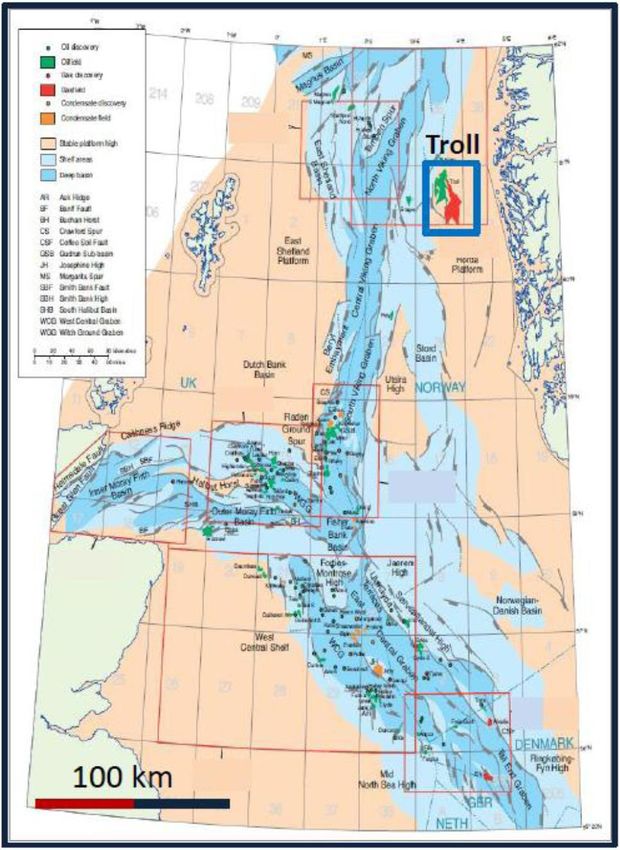
The Troll Field is a prolific oil and gas field located in about 350 m of water on the Horda Platform in the Northern North Sea (Figure 1)
(Fraser et al., 2003). The reservoir is composed of four sequences of stacked coastal to shallow-marine parasequences. Each of these
parasequences typically displays an upward-shallowing trend starting at the base from offshore to lower shoreface siltstones into upper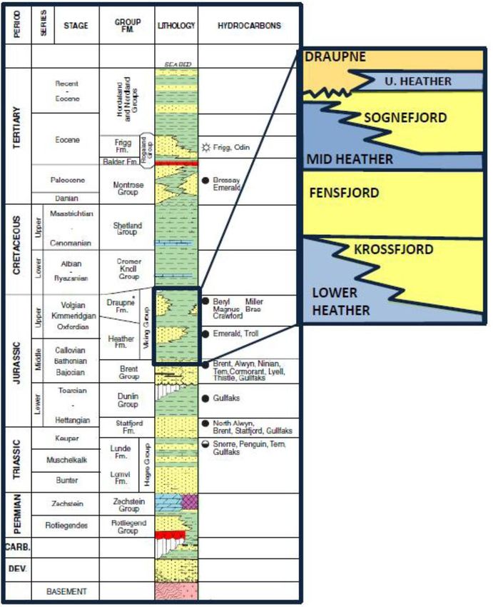
shoreface to foreshore sandstones of a migrating spit, and back-barrier tidal flat to coastal plain heterolithic deposits (Dreyer et al., 2005).
Presently over 300 wells have been drilled into the reservoir formation. Individual target sands are 3-45-m thick units of medium- to coarse-
grained sands, which are mostly unconsolidated with permeability of 1–30 D (called the ‘C-sands’). These alternate with poorer quality, finer
grained micaceous deposits (called the ‘M-sands’) which are not usually targeted (Dreyer et al., 2005). The study area, which is in the Troll
West block has series of parallel curvilinear belts of oil column (1 - 25 m) that formed where the coarse sands intersect the oil zone. These are
usually drained with horizontal wells. Currently, in-fill wells are being drilled with long horizontal production sections which seek to drain as
large an area of the thin oil column as possible. A good understanding of the sequence stratigraphic architecture including the finer-scale-
facies distribution and heterogeneities are essential to allow the oil extraction process to be performed with greater efficiency.

The sequence stratigraphy of the Sognefjord Formation (Figure 2) has been discussed by Dreyer et al. (2005). It consist of two composite
sequences; namely, the Upper and Lower Sognefjord, each of which contains two basic sequences (corresponding to 2-, 3-, 4- and 5-series)
and their system tracts corresponding to individual reservoir zones; e.g., 3Ac, 3Bc, 3Cc1, etc. Although this model has been very useful in
predicting facies distribution within most of the sequences and their system tracts, four horizontal wells (31/5-I-13 Y1H, Y2H, Y2HT2, Y3H)
drilled into the 3Cc2 system tract, however, encountered fine-grained micaceous sands (M-sands), where coarse-grained sands (C-sands) were
predicted (Figure 3). This project, therefore, focused on the 3-series sequence, especially, the 3cc2 system tract. The 3Cc2 unit had earlier
been interpreted to have been deposited during forced regressions with the 3Cc2 unit representing an ebb-tidal delta.

                                                                    Method

To tackle the problem mentioned above, seismic stratigraphic, seismic facies, and seismic attribute analyses were carried out on a 3-D seismic
cube in the Troll West region. Three cored wells that penetrated the 3-series were also analyzed and were then calibrated with ten uncored
wells, enabling detailed facies interpretation, depositional environments analysis, and sequence stratigraphic correlation to be done. This
information was then combined to generate an updated sequence-stratigraphic-constrained geological model for the 3-series of the Sognefjord
Formation with particular focus on the 3Cc2 unit.

                                                           Geological Background

The Troll Field occupies a large part of the Northern Horda platform located within the Northern North Sea province, a part of the North Sea
Mesozoic rift system (Brzozowska et al., 2003) (Figure 1). The Northern North Sea evolved throughout the Mesozoic as the 40-100 km wide,
NNE-trending Viking Graben (Horstad and Larter, 1997). The Viking Graben is flanked by terraces of fault blocks tilted away from the
graben (Figure 1). The East Shetland Basin lies to the west while the Horda Platform lies to the east of the main graben (Zanella and Coward,
2003) (Figure 1). Although the Horda Platform was the locus of E-W extension in the Early Triassic rifting event, it remained mildly
deformed during the Late Jurassic to earliest Cretaceous extension that formed the Viking Graben (Bolle 1992).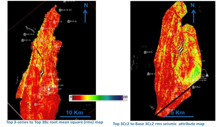
The stratigraphy of the Northern Viking Graben spans from Devonian to Tertiary (Figure 2). On the Horda Platform the Viking Group occurs
as a well developed sand-rich succession comprising the Bathonian Krossfjord Formation, late Bathonian to Callovian Fensfjord Formation
and the Callovian to early Oxfordian Sognefjord Formation separated by shallow-marine Heather Formation (Stewart et al., 1995). In the
Troll West field, clastic wedges of two different sequence stratigraphic scales are recognized in the Sognefjord Formation: the Lower
Sognefjord composite sequence and the Upper Sognefjord composite sequence. These two composite sequences encompass four basic
sequences and their system tracts which largely forms the reservoir. The basic sequences are referred to as 2-, 3-, 4-, and 5-series.

Dreyer et al. (2005) reported that these sequences were formed by the progradation and backstepping of a series of large wave-, tide- and
fluvial- influenced deltas ‘sensu’ Coleman and Wright (1975). This tripartite classification of deltas is still widely used although more recent
works have classified deltas based on other parameters, such as grain size, water depth and feeder type (Reading and Collinson, 1996). The
application of this tripartite model in interpreting ancient delta is not without controversy (Bhattacharya and Giosan, 2003). One issue is the
general tendency of placing a delta within one end member, thereby undermining the fact that most deltas have a mixed influence (Galloway
and Hobday, 1996). This is especially crucial in the subsurface, where predicting facies distribution from few unrepresentative sample points
(i.e., well data) is not uncommon; this results in either overestimating or underestimating both the facies distribution and the reservoir
heterogeneity (Bhattacharya and Giosan, 2003). Recent studies on some modern deltas (e.g., Sfantul Gheorghe lobe of the Danube Delta in
Romania, Brazos Delta at Freeport in Texas, USA, Guadiana Delta in the Atlantic section of the southwestern Iberian Peninsula, modern
Damietta branch of the Nile Delta, Brazilian Delta, Paraibo du Sul Delta, Rio Rice Delta) all show asymmetric delta lobes. According to
Bhattacharya and Giosan, (2003), these asymmetric delta lobes show a difference in facies between updrift and downdrift areas. The updrift
area consists of beach ridge plain of longshore derived sands deposited as a result of the barrier effect exerted by the riverine plume while the
downdrift side is a succession of elongate sandy ridges separated by mud filled toughs.

                                                                     Results

Sequence Stratigraphic Evolution of the 3-Series

The 3-series is bounded at the base and top by the Top 2 and Top 3 reflectors, respectively (Figures 4, 5, and 6). Both of these reflectors act as
downlap surfaces for the overlying 3-series and 4 series, respectively. These bounding surfaces have been called maximum flooding surfaces,
and they thus bound the 3-series sequence sensu Galloway (1989). Four seismic horizon (top 3Ac, top 3Bc, top 3Cc1, and top 3Cc2) were
obvious within the 3-series separating it into five seismic stratigraphic units corresponding to reservoir zones; namely; 3Ac, 3Bc, 3Cc1, 3Cc2,
and 3Dc (Figures 5 and 6). In cores each of these system tract typically consists of a coarsening-upward succession made up of lower
shoreface, micaceous, silty sands grading upwards into trough cross-bedded, upper shoreface, medium to coarse sand and planar-bedded,
foreshore, coarse to very coarse sands with transgressive lag capping some units (Figure 10).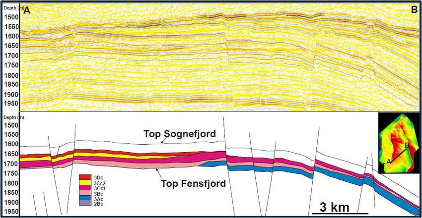
The 3Ac Unit
The 3Ac system tract is the first prograding wedge following the drowning of the underlying 2-series. Seismic mapping and well-log
correlation of the 3Ac unit relative to the underlying 2-series implies progradation towards the west (Figures 7, 11). No core was recovered
from this unit; however, gamma ray (GR) logs show a gradationally based ‘upward-cleaning’ trend, suggestive of an increasing energy level
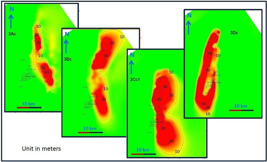
interpreted as shelf facies association coarsening upwards into strandplain/spit facies association (Figure 10). Sand isochore shows an
elongated morphology oriented in an approximately N-S direction (Figure 9). This unit has, therefore, been interpreted as a prograding spit
system formed during an early highstand, as it is bounded below by a maximum flooding surface.
The 3Bc Unit
Seismic mapping of the 3Bc shows series of well developed clinoform building both westward and southward. On the seismic and with well
correlation (Figures 5, 11), this unit is seen to step farther basinward (westward) than the underling 3Ac unit. No core was recovered from this
unit, but a gradationally based, upward-cleaning GR log trend corresponds to a coarsening-upward trend that is seen in wells (Figure 11). This
trend is interpreted to be shelf-facies association coarsening upwards into strandplain/spit facies association. The sand isochore for this unit
suggests that the elongated spit morphology of the 3Ac unit is still maintained during the deposition of this system tract (Figure 9). This unit
displays a strongly progradational trend, and its position within the 3-series suggests that it might have been formed during a highstand
system tract.
The 3Cc1 Unit
Attribute mapping (Figure 8) of the 3Cc1unit shows a series of linear features which in a spit system would correspond to lithology and dip
change along clinoform break. The sand isochore for this unit also shows an elongate shape with an approximate N-S orientation (Figure 9).
Sharp-based erosive surfaces have been identified in some wells (Dreyer et al., 2005), corresponding to regressive surface of marine erosion.
The offlapping clinoform pattern and pronounced basinward stepping suggest deposits during forced regressions.
The 3Cc2 unit
The 3Cc2 unit shows a well defined erosional truncation on the underlying 3Cc1unit (Figure 6). It has a sharply defined areal extent (14 X 8
km) (Figure 7) and bears marked incised-fill sequence with pronounced clinoforms well displayed over most of its areal extent. The 3Cc2 unit
exhibits an incised proximal cut, basinward expansion and a change in seismic facies from small clinoforms with discontinuous U-shaped
reflectors to large steep clinoform distally. This might suggest a more heterolithic facies located behind a prograding and sand-rich system
distally. The local areal extent of this elongate-shaped unit suggests that the deposit must have formed as a lowstand wedge. The previous
interpretation of Dreyer et al. (2005) proposes an ebb-tide deltaic system for this unit. However, seismic-amplitude analysis (Figure 8)
displays linear features toward the western part of the unit that might represent strandplain or spit deposits. In addition, there is no strong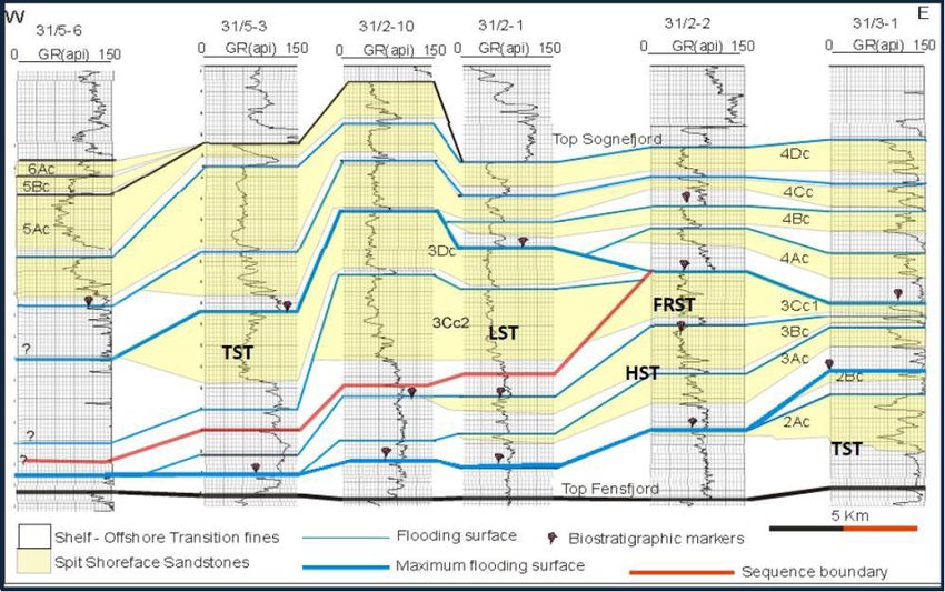
evidence for tide action, as trough cross-bedding and planar-cross and parallel-bedding dominate the few cores that penetrate the 3Cc2 unit
(Figure 10). The strong southward-oriented longshore current that existed during the deposition of the 3-series combined with the westward-
oriented fluvio-tidal processes to form an asymmetric wave-influenced delta ‘sensu’ Bhattacharya and Giosan, (2003), as discussed below.

       The 3Dc unit

The 3Dc unit overlies the forced regressive and lowstand deposit of the 3Cc1 and 3Cc2 units, respectively (Figure 6). Seismic attribute
mapping shows a well defined linear geometry for this system tract, interpreted to correspond to clinoform break of a prograding spit system.
Well developed sand-rich spit facies appears to be restricted to the eastern area, while to the west the 3-series grades into heterolithic tidal
facies unit. This is shown on seismic data as well developed clinoforms to the east, changing into chaotic seismic expression to the west. In
core this unit displays a coarsening-upward trend beginning with lower shoreface, silty sands grading upwards into trough cross-bedded,
upper shoreface sand and planar-bedded, foreshore sands. Sand isochore shows N-S-elongated morphology suggesting that the spit system
was still well developed during the deposition of this unit. The 3Dc seismic horizon bounds the 3Dc system tract. This horizon acts as a major
downlap surface for the overlying 4 series and is interpreted as a maximum flooding surface (Figure 11). The 3Dc is interpreted to be a
transgressive system tract.

Facies Distribution within the 3cc2 Unit and Depositional Model

       Facies Distribution

Initial models (Dreyer et al., 2005) developed for the 3Cc2 unit was that of an ebb-tide delta to estuary mouth bar developed during forced
regressions. This interpretation, however, could not predict the facies variation found in the four horizontal wells, which encountered fine-
grained sands where reservoir quality sands were predicted.

An alternative model is hereby proposed to explain the facies distribution within the 3Cc2 unit. The depositional model described here is
based on seismic-stratigraphic, facies and attribute interpretations, facies interpretation from cores, well-log correlation, knowledge of the
sedimentary processes and environments, and modern analogues. This model is considered plausible for two reasons:
    1. It explains the occurrence of coarse sand in more distal area, as seen in wells 31/5-5, 31/2-10, and 31/2-1, but fine-grained, micaceous
       sand in proximal area to the south of the 3Cc2 lobe, as seen in wells 31/2-I-13 Y1H, Y2H, Y2HT2, and Y3H.
    2. It helps understand the asymmetry in facies distribution, with well 31/2-I-12Y1H lying in the updrift section of the incised channel
       system containing coarse sands, whereas well 31/2-I-13Y2H in similar position downdrift contains carbonate-cemented, micaceous,
       fine-grained sands.

In general, an incised surface marks the base of the 3Cc2 series to the east. This incision suggests fluvial downcutting and westward sediment
transport following sea-level lowstand and exposure of the older 3Cc1 forced regressive unit. Also a southward-oriented longshore current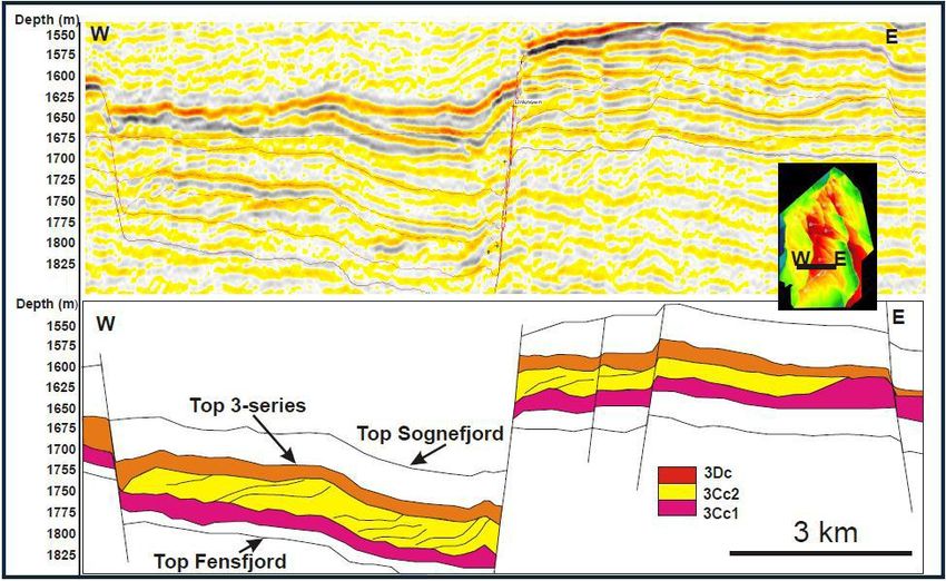
dominated during the deposition of the 3Cc2 wedge. This is well documented by the spit morphology of both the system tracts overlying and
underlying the 3Cc2. The model proposed is discussed below:

       The Asymmetric Wave-Influenced Deltaic Model
       (‘Sensu’ Bhattacharya and Giosan, 2003)

This model assumes that the southward-oriented longshore current and the westward- oriented fluvial effluent to have had relatively similar
energy. It proposes that facies distribution within the lowstand delta resulted from the combination of the longshore current and the fluvio-
tidal system are asymmetric with facies distribution and sand architecture differs in the updrift and downdrift parts of the deltaic system
(Figure 10b and Figure 12). In the updrift section, sediments supplied by the southward-oriented longshore current eroded sand from older
3Cc1 upper shoreface to foreshore deposits. The deposits that formed are made up of amalgamated coarse sandy succession as seen in well
31/2-10 because the fluvial effluent acted as a barrier to the longshore current, thus trapping coarse sand facies updrift. Whereas in the
downdrift section, sand body was constructed by the fluvial system that supplied both fine-grained sands associated with the back-basin tidal
system located to the east and coarse sand reworked from top 3Cc1 spit sands. Typical of this system, a sand-rich barrier bar formed in the
downdrift portion with a lagoon or estuarine system attached behind. Wells drilled in the proximal portion of the downdrift side encountered
fine-grained, micaceous lagoonal sediment. The lagoonal setting favoured the growth of calcareous organisms that dissolved and
reprecipitated during diagenesis to cement the fine-grained sands. This might explain why wells (31/2-I-13 Y1H/Y2H/Y2HT2/Y3H)
primarily encountered extensively cemented fine-grained sands in their proximal reach. Wells 31/5-5 and 31/5H-5H are here considered to
have targeted barrier-bar sands constructed by the fluvial system and modified by longshore current (Figure 12).

Seismic attribute map for the 3Cc2 unit (Figure 8) shows series of N-S-oriented linear features that suggest clinoform break of prograding spit
or strandplain system. Distinct thinning in the middle part of the 3Cc1 isochore (Figure 9) also supports erosion and westward sediment
transport by a fluvio tidal system. This system is comparable to the modern Sfantul Gheorghe lobe of the Danube delta in the northwestern
margin of the Black Sea (Figure 13). The updrift wing of this delta consists of succession of amalgamated sand known as the Saraturile
Formation whereas the downdrift wing is formed by subparallel series of sand, shoestring ridges encased in delta plain muds (Bhattacharya
and Giosan, 2003).

                                                                 Discussion

The morphology of a shoreline results from the interplay between sediment delivery by a fluvial system and basinal forces that reworks these
sediments influencing the sand body distribution. Depending on the relative strength of the fluvial input compared to that of the longshore
current a continuum of sedimentary environments will be formed ranging from spit system into deflected wave-influenced delta through
asymmetric wave influenced delta and symmetric wave-influenced deltas with decreasing basinal strength (Bhattacharya and Giosan, 2003).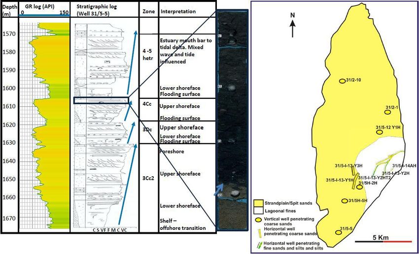
The sequence stratigraphic evolution of the 3-series of Sognefjord Formation of the Troll Field has here been evaluated in order to understand
facies distribution within its component system tracts, especially the 3Cc2 unit. The initial interpretation of the 3Cc2 unit as an ebb-tide delta
which developed during forced regression could not predict finer-scale facies distribution within this system tract as wells penetrating it
typically encountered fine-grained sands where reservoir quality sands were predicted. 3-D seismic interpretation, core description, and well-
log correlation have resulted in a better understanding of the of the 3-series sequence.

The Sognefjord Formation of the Troll Field, Northern North Sea developed following the drowning of the Fensfjord delta. At the initial stage,
a lobate-shaped delta containing two sandstone wedges recorded a backstepping-parasequence-stacking pattern as seen on seismic and well-
log correlation (Figure 11). This is the 2-series, and it has been interpreted to have formed during a transgressive system tract. A major
flooding event corresponding to a maximum flooding surface separates the 2-series from the overlying 3-series during the Callovian period.
At that time the Boreal sea in the north linked with the Tethyan Ocean to the south across the former Mid North Sea High (Husmo et al.,
2003; Fraser et al., 2003). This connection created an open seaway through which strong marine current flowed southward, much like the
present day English Channel. This strong current changed the previous symmetrical delta morphology charactering the 2-series into an
asymmetrical one, dominated by an approximately N-S-elongated spit system. The spit prograded both westward and southward though time
as recorded by clinoform dips on seismic sections with linear features displayed on amplitude maps, interpreted to correspond to clinoform
break of these linear spit system (Figure 8). Sand isochores for the 3-series sand also support this elongated spit geometry (Figure 9).

The first two 3-series parasequences (3Ac and 3Bc) display a marked progradational trend as seen on seismic and well-log correlation and
hence is suggestive of highstand normal regressive deposit following the transgressive system tract characterising the 2-series. Basinward
translation, proximal pinchout, and sharp-based contact with underlying unit displayed by the 3Cc1 are indicative of forced regressive system
tract (Dreyer et al., 2005). Seismic mapping and sand isochore for this unit show marked seaward stepping (Figure 9). Pronounced incision
and the limited areal extent are seen on seismic to characterize the 3Cc2 lobe (Figures 6 and 7), which was interpreted to be a lowstand wedge.
Two cores penetrating this unit indicate a coarsening-upward succession starting from bioturbated, lower shoreface fine sands passing
upwards into trough cross-bedded, upper shoreface medium- to coarse-grained sand and planar-bedded, foreshore coarse sands in cores.
Results indicate that this lowstand wedge neither developed typical spit geometry nor a symmetrical delta morphology. Facies distribution
and heterogeneity within this 3Cc2 unit was a result of the interplay between the southward-oriented longshore current and the westward-
directed fluvio-tidal system. Characteristic of such a system, an asymmetric delta formed with facies distribution differing in both updrift and
downdrift sector of the incised channel system (Bhattacharya and Giosan, 2003). The updrift section of this 3Cc2 unit is interpreted to consist
of coarse-grained, amalgamated sand body formed by longshore current reworking older spit, shoreface sands (Figure 12). The fluvial
effluent acted as a barrier trapping longshore derived sediments updrift, resulting in sand body constructed in the downdrift section of the
fluvio-tidal system that supplied both fine-grained sands associated with the back-basin tidal system located to the east and coarse sand
reworked from spit-platform sands, thus forming a sand-rich barrier-bar system distally with a lagoon attached behind (Figure 12). Hence
reservoir quality sands for the 3Cc2 unit is suggested to be in the updrift sector and the distal portion of the downdrift section, whereas fine-
grained heterolithic deposit will characterize the proximal sector on the downdrift part (Figures 12 and 13).
A potential modern analogue to the 3Cc2 unit system would be the Sfantul Gheorghe lobe of the Danube delta in the northwestern margin of
the Black Sea (Figure 13). The updrift wing of the modern Sfantul Gheorghe lobe consists of a succession of amalgamated beach ridges,
known as the Saraturile Formation, while the downdrift wing is characterized by a subparallel series of sandy shoestring ridges encased in
delta-plain mud (Figure13).

                                                                 References

Bhattacharya, J.P., and L. Giosan, 2003, Wave-influenced deltas: geomorphological implications for facies reconstruction: Sedimentology, v.
50, p. 187–210.

Bolle, L., 1992, Troll Field: Norway’s giant offshore gas field, in M.T. Halibouty, (ed.), Giant Oil and Gas Fields of the Decade 1978–1988:
AAPG Memoir 54, p. 447–458.

Brzozowska, J., S., Eriksen, L. Holm., and S. Olsen, 2003, Exploration history, in D. Evans, C. Graham, A. Armour, and P. Bathurst, (eds.),
The Millennium Atlas: Petroleum geology of the Central and Northern North Sea: Geological Society, London, England, p. 331-343.

Coleman, J.M., and L.D. Wright, 1975, Modern river deltas: variability of processes and sand bodies, in M.L. Broussard, (ed.), Deltas,
Models for Exploration: Houston Geological Society, Houston, Texas, p. 99–149.

Dreyer, T., M. Whitaker, J. Dexter, H. Flesche, and E. Larsen, 2005, From spit system to tide-dominated delta, in A.G. Dore, and B. Vining,
(eds.), Petroleum Geology: North-West Europe and Global Perspectives-Proceedings of the 6th Petroleum Geology Conference: Geological
Society, London, England, article I.D 093, p. 1-27.

Fraser, S.I., A.M. Robinson, H.D. Johnson, J.R. Underhill, D.G.A. Kadolsky, R. Connell, P. Johanesen, and R. Ravnås, 2003, Lower and
Middle Jurassic, in D. Evans, C. Graham, A. Armour, and P. Bathurst, (eds.), The Millennium Atlas: Petroleum geology of the Central and
Northern North Sea: Geological Society, London, England, p. 157-173.

Galloway, W.E., 1989, Genetic stratigraphic sequences in basin analysis I; Architecture and genesis of flooding-surface bounded depositional
units: AAPG Bulletin 73, p. 125-142.

Horstad, I., and S.R. Larter, 1997, Petroleum migration, alteration and remigration within Troll Field, Norwegian North Sea: AAPG Bulletin,
v. 81, p. 222-248.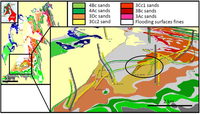
Husmo, T., G.P Hamar, O. Høiland, E.P., Johanessen, A. Rømuld, A.M Spencer, and R. Titterton, 2003, Lower and Middle Jurassic, in D.
Evans, C. Graham, A. Armour, and P. Bathurst, (eds.), The Millennium Atlas: Petroleum geology of the Central and Northern North Sea:
Geological Society, London, England, p. 129-155.

Lee, M.J., and Y.J. Hwang, 1993, Tectonic evolution and structural styles of the East Shetland Basin, in J.R. Parker, (ed.), Petroleum Geology
of Northwest Europe: Proceedings of the 4th Conference: The Geological Society, London, England, p. 1137-1149.

Reading, H.G., and J.D. Collinson, 1996, Clastic coasts, in H.G. Reading, (ed.), Sedimentary Environments: Processes, Facies and
Stratigraphy: Blackwell Science, Oxford, England, p.154–231.

Stewart, D.J., M. Schwander, and L. Bolle, 1995. Jurassic depositional systems of the Horda Platform, Norwegian North Sea: Practical
consequences of applying sequence stratigraphic models, in R.J. Steel, (ed.), Sequence Stratigraphy of the Northwest European Margin:
Norwegian Petroleum Society Special Publication, Elsevier, Amsterdam, The Netherlands, v. 5, p. 291–323.

Zanella, E., and M.P. Coward, 2003, Structural framework, in D. Evans, C. Graham, A. Armour, and P. Bathurst, (eds.), The Millennium
Atlas: Petroleum geology of the Central and Northern North Sea: Geological Society, London, England, p. 45-59.
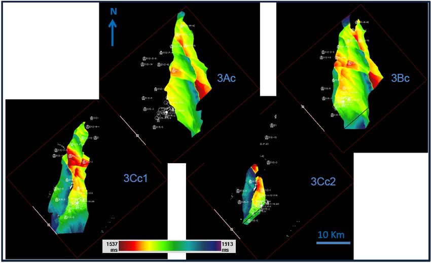
Figure 1. Location of the Troll Field in the North Sea (after Fraser et al., 2003).
Figure 2. Stratigraphy of the North Viking Graben (after Lee and Hwang, 1993).
Figure 3. Map of the Sognefjord Formation of the Troll West taken at the oil-water contact (OWC) showing the 3Cc2 lobe (yellow). Coloured
intervals represent different reservoir horizons corresponding to C-sands. White colour represents micaceous, silty sands. Pale yellow shows
region below the OWC. In the well traces, colours represent gamma-ray (GR) response with green representing shales, while yellow
represents clean sands. Note the green GR response (green) where clean 3Cc2 sand was predicted (circled portion).
Figure 4. Cartoon sketch of the stratigraphic relationship of the 3-series within the Sognefjord Formation based on seismic interpretation.
Figure 5. Seismic stratigraphic relationship within the 3-series.
Figure 6. Relationship between the 3Cc2 unit (yellow) relative to other units within the 3-series. Note incision to the east, and westward-
prograding clinoforms more developed towards the west.
Figure 7. Top 3AC, 3Bc, 3Cc1, and 3Cc2 time-structure seismic surfaces. Average areal extent is about 15-20 km X 35-50 km except for the
3Cc2 unit, with limited areal extent (10 X 20 km).
Figure 8. Attribute maps showing series of N-S-elongated feature. These features are interpreted to correspond to dip and lithology change
along clinoform break of a prograding system.
Figure 9. Sand isochores for various sand wedges in the 3-series (units in meters). Elongated shape is related to the southward-oriented
longshore current.
Figure 10. a. Stratigraphic log for well 31/5-5 (left). b. Areal distribution of the 3Cc2 unit (right).
Figure 11. W-E regional correlation showing stratigraphic relationship of the Sognefjord Formation.
Figure 12. Depositional model for the 3Cc2 unit. (Asymmetric wave influence delta model)
Figure 13. Modern analogue for the 3Cc2 unit. The Sfantul Gheorghe lobe of the Danube delta. (Google earth image, 2009)
You can also read