Technique Guide Patello-Femoral Arthroplasty - Biotechpromed
←
→
Page content transcription
If your browser does not render page correctly, please read the page content below
Technique Guide
                                                               Patello-Femoral Arthroplasty

The HemiCAP® Patello-Femoral Resurfacing Systems
restore the unique articular surface geometry of the Patella
and the Femoral Trochlear groove; creating a congruent
pathway by using an intraoperative 3 dimensional mapping
system and contoured articular resurfacing implants.

                                             Chapter One
                                                      HemiCAP® PF Classic

                                             Chapter Two
                                                      HemiCAP® PF W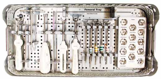
Etiology and Surgical Management of Patello-Femoral Arthritis
    As described by Philip Schöttle, M.D., Associate Professor, Head of Orthopedics and Sportsmedicine Isar Medical Centre,
    Munich, Germany and Andreas Imhoff, M.D., Professor of Orthopaedic Surgery and Traumatology, Director Department of
    Orthopaedic Sports Medicine, Hospital Rechts der Isar, University of Munich, Germany

    Patello-femoral degeneration is a complex entity which requires careful examination and surgical
    planning in order to treat the underlying cause and associated degeneration. Depending on the
    etiology, concomitant procedures will be an important component for a successful outcome with
    the HemiCAP® W Patello-Femoral Resurfacing system. Patient management is guided by two
    main diagnostic groups:

    Group A: PF arthritis due to direct compression trauma, traumatic dislocation, OCD, high BMI and
    overuse. Depending on defect size, resurfacing with the 20mm focal PF HemiCAP® or the larger
    HemiCAP® W component can restore an anatomic inlay surface.

    Group B: Complex etiology with PF arthritis due to malalignment (valgus, rotational deformities),
    trochlear morphology (dysplasia), ligamentous instability, and patella mal-positioning. HemiCAP®
    WPatello-Femoral Resurfacing should be augmented by concomitant procedures to address the
    underlying pathology.

    The HemiCAP® W Patello-Femoral System supports both simple and complex PF surface recon-
    structions with its array of congruent articular inlay components for both the trochlea and patella.

2
Surgical Approaches for Arthrosurface
HemiCAP WArthroplasty

The patient is positioned in the supine position, with a tourniquet on the proximal thigh. The
tourniquet is inflated and a longitudinal incision centered over the patella is made, extending from
the quadriceps tendon down just medial of the tubercle. The subcutaneous tissue and superficial
fascia are reflected over the patella medially by a blunt, sharp dissection. The fascia is divided and
retracted, making sure to leave a cuff of tissue on the medial border of the patella for re-suture or
advancement. The dissection is deep in between the vastus medialis muscle and the medial
border of the quadriceps tendon and the capsule subsequently incised along the medial border of
the patella and patellar tendon. As an alternative, a subvastus approach can be utilized. This
approach preserves the vascularity of the patella as well as the quadriceps tendon and the VMO
attachment. The same straight longitudinal incision is made, at which point the superficial fascia is
incised slightly medial to the patella and bluntly dissected off of the vastus medialis muscle fascia,
down to the muscle insertion. The inferior edge of the vastus medialis is identified and bluntly
dissected off of the periosteum and intramuscular septum for a distance of 8-10 centimeters
proximal to the adductor tubercle. The tendinous insertion of the muscle on the medial patellar
retinaculum is identified and the vastus medialis muscle is lifted anteriorly. An L-shaped arthrotomy,
beginning medially through the vastus insertion on the medial patellar retinaculum, is performed,
carrying it along the medial edge of the patella, at which time the patella can be everted laterally.
Upon completion of the procedure, perform a layered closure of biomechanically important
structures according to accepted surgical technique.

                                                                                                         3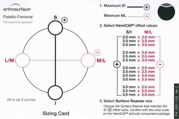
Chapter Guide Patello-Femoral Arthroplasty

          Chapter One (Pages 5-18)

                                 PF Classic
                   “With proper implantation of the limited trochlear resurfacing device at the site of the
                   trochlear defect, peak pressures and force is normalized leading to decreased edge
                   loading. This normalization of contact area, pressure, and force may translate into
                   decreased clinical symptoms and delayed progression of chondral disease.”
                   Matthew Provencher, MD. Patellofemoral Kinematics After Limited Resurfacing of the Trochlea.
                   The Journal of Knee Surgery, 2009

          Chapter Two (Pages 19-30)

                                  PF W
                   “Patients treated with PFA demonstrated similar results with respect to pain relief, but
                   showed improved function and return to activity when compared with the patients
                   treated with TKA. Patello-femoral arthroplasty patients also experienced less blood
                   loss, fewer complications, and shorter hospital stay following surgery. Our results
                   indicate that PFA is a less invasive treatment option for patients with isolated PA,
                   yielding early outcomes that compare favorably with TKA.”
                   Diane L. Dahm, MD. Patellofemoral Arthroplasty Versus Total Knee Arthroplasty in Patients with
                   Isolated Patellofemoral Osteoarthritis. The American Journal of Orthopedics, October 2010

4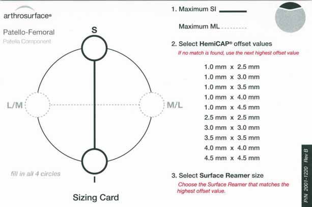
PF Classic

            KEY FEATURES:
Anatomic “Inlay” with proven threaded fixation
Minimal bone removal maintains future options
   Designed for localized defects and early
                 intervention

                                                 5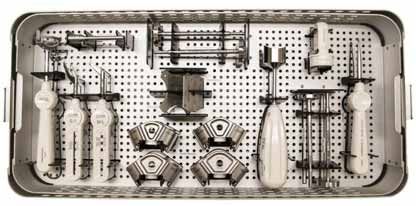
Description
    The HemiCAP® Patello-Femoral Resurfacing Prosthesis incorporates a distal femoral trochlear
    surface articular component that mates to a taper post via a taper interlock, and an all-
    polyethylene patella component. The prosthesis is intended to be used in cemented arthroplasty.

    Materials
    Femoral Resurfacing Component:            Cobalt-Chronium Alloy (Co-Cr-Mo)
    Surface Coating:                          Titanium (CPTi)
    Taper Post:                               Titanium Alloy (Ti-6Al-4V)
    Patella Component:                        Ultra-High-Molecular Weight Polyethylene (UHMWPE)

    Indications
    The HemiCAP® Patello-Femoral Resurfacing Prosthesis is intended to be used in cemented arthroplasty
    in patients with osteoarthritis limited to the distal patello-femoral joint, patients with a history of
    patellar dislocation or patellar fracture, and those patients with failed previous surgery (arthroscopy,
    tibial tubercle elevation, lateral release, etc.) where pain, deformity or dysfunction persists.
    Patient selection factors to be considered include:
        1) Need to obtain pain relief and improve function
        2) Patient’s tibio-femoral joint is substantially normal
        3) Patient exhibits no significant mechanical axis deformity
        4) Patient’s menisci and cruciates are intact with good joint stability, and good range of motion
        5) Patient’s overall well-being is good, including the ability and willingness to follow instructions
           and comply with activity restrictions

    Contraindications
    Absolute contraindications include:
       1) Defects that are not localized
       2) Inflammatory degenerative joint disease, rheumatoid arthritis, infection, sepsis,
          or osteomyelitis
       3) Patients that have a known sensitivity to materials typically used in orthopedic
          prosthetic devices or bone cements
    Relative contraindications include:
       1) Uncooperative patient or patient incapable of following pre-operative and
          post-operative instructions
       2) Metabolic disorders, which may impair the formation or healing of bone; osteoporosis
       3) Infections at remote sites, which may spread to the implant site
       4) Rapid joint destruction or bone resorption visible on roentgenogram
       5) Chronic instability or deficient soft tissues and other support structures
       6) Vascular or muscular insufficiency
       7) Inadequate skin, musculotendinus or neurovascular system status

6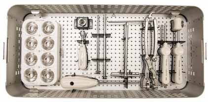
Surgical Technique (HemiCAP® PF Classic Trochlear Component)

1. With knee at 90 degrees flexion, locate the Drill Guide in
   an anterior position to develop a working axis normal to
   the trochlear articular surface. Place the Guide Pin into a
   cannulated powered drill and secure at the etch marking
   on the Guide Pin. Advance the Guide Pin through the
   Drill Guide and into the bone making sure that it is
   central to the defect.

   Note: It is important to verify that the Drill Guide is seated
   on the curved surface such that all 4 points of contact are
   established on the articular surface. Feet on the Drill
   Guide will orient superior and inferior. A normal axis is
   necessary for proper implant fit.

2. Place the Step Drill completely over the Guide Pin.
   Verify that the cannulated powered drill is not bending
   the Guide Pin and advance until the proximal shoulder
   of the Step Drill is flush to the articular surface. (Use
   lavage during drilling to prevent possible tissue damage
   from heat effects). Should the Guide Pin loosen, use the
   Step Drill to re-center the Guide Pin in the pilot hole and
   advance into the bone.

3. Advance the Tap into the pilot hole to the etched
   depth marking.

                                                                    Chapter One: HemiCAP PF Classic   7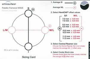
4. Place the Hex Driver onto the Taper Post.
       Advance the Taper Post until the line on the
       Hex Driver is flush with the contour of the
       native cartilage surface in the superior to
       inferior plane.

    5. Clean the taper in the Taper Post with the
       Taper Cleaner. Place the Trial Cap into the
       Taper Post to confirm correct depth of the
       Taper Post. The height of the Trial Cap must
       be flush or slightly below the existing articular
       cartilage surface in the superior to inferior plane
       to avoid the Femoral Trochlear Component
       from being placed proud or above the surface
       of the defect. Adjust depth if needed using the
       Driver to rotate the Taper Post (rotate clockwise
       to advance and counterclockwise to retract).
       Remove the Trial Cap.

8
6. Place the Centering Shaft into the taper of the Taper
   Post. Place the Contact Probe over the Centering
   Shaft and rotate around the shaft. Use light pressure
   on the Contact Probe to ensure proper contact
   with the articular surface. Read the Contact Probe
   to obtain positive (+) superior/inferior offsets, and
   negative (-) medial/lateral offsets. Mark each of the
   identified offsets on the appropriate Sizing Card. Use
   the Sizing Card to record the maximum superior/
   inferior offset and the minimum medial/lateral offset.

7. Remove the Centering Shaft and replace with
   the Guide Pin. Advance the Circular Scalpel onto
   the articular surface to create a cut through the
   articular surface.

8. Choose the appropriate Femoral Reamer based
   on the maximum superior/inferior (+) offset from
   the Sizing Card. Confirm selection by matching
   the color code on the Femoral Resurfacing
   Component package with the colored band on
   the Femoral Reamer shaft. Advance the Femoral
   Reamer over the Guide Pin until it contacts the
   top surface on the Taper Post. (Use lavage during
   drilling to prevent possible tissue damage from heat
   effects). Make sure not to bend the Guide Pin
   during drilling as it may result in malalignment of
   the Femoral Trochlear Component.

                                                            Chapter One: HemiCAP PF Classic   9
9. Clean the taper in the Taper Post with the
        Taper Cleaner and remove any debris from the
        surrounding implant bed.

     10. Place the Sizing Trial into the defect that
         matches the offset profile of the chosen
         Femoral Trochlear Component. Confirm
         the fit of the Sizing Trial so that all margins
         are congruent or slightly recessed to the
         edge of the surrounding articular surface.

10
NOTE: Prepare and implant the
Patella Component (p. 12) prior
to the final placement of the
Femoral Trochlear Component.
11. Prior to placing the Femoral Trochlear
Component on the Implant Holder, make
sure that sufficient suction is present to hold
the device on the distal suction cup. Orient
the etch marks on the back of the Femoral
Trochlear Component with the etch mark
on the handle of the Implant Holder.
Apply a small amount of low-viscosity bone
cement onto the underside of the Trochlear
Component. Insert into the taper of the
Taper Post.
12. Firmly mallet the Impactor until the
Femoral Trochlear Component is
completely seated.
Chapter One: HemiCAP PF Classic 11Surgical Technique (HemiCAP® PF Classic Patella Component)
1. Confirm that the patella’s anterior to posterior
thickness will accept the Patella Component
(typically a 6.5mm reaming depth). With
the knee at 90 degrees flexion, locate the
Alignment Guide so that the pin fits into
the Taper Post. While observing the range
of motion, identify target placement of the
Patella Component using the pointer on the
Alignment Guide to transfer the Taper Post’s
central axis. (Typically 20 to 30 degrees of
flexion). Use slight pressure against the patella
so that the pointer on the Alignment Guide
creates an indentation on the patella surface.
2. Place the Drill Guide so that its central
axis passes through the Alignment Guide
indentation created on the patella surface. Drill
the Guide Pin through until it engages the
opposite cortex of the patella.
Note: It is important to verify that the Drill Guide
is seated on the curved surface such that all 4
points of contact are established on the articular
surface. Feet on the Drill Guide will typically orient
medial and lateral. A normal axis is necessary for
proper implant fit.
123. Remove the Drill Guide. Advance the Circular Scalpel
onto the articular surface to create a cut through the
articular surface. Place the Step Drill over the Guide
Pin. Verify that the cannulated powered drill is not
bending the Guide Pin and advance until the distal
shoulder of the Step Drill is flush to the articular
surface. (Use lavage during drilling to prevent possible
tissue damage from heat effects). Should the Guide Pin
loosen, use the Step Drill to re-center the Guide Pin in
the pilot hole and advance into the bone.
14mm Patella Drill Depth
Stop Mark
4. Using a cannulated powered drill, advance the Patella
Centering Shaft over the Guide Pin until it reaches
the distal laser depth marking.
5. Place the Contact Probe over the Patella Centering
Shaft. Read the Contact Probe to take medial, lateral,
superior, and inferior offsets and mark them onto the
appropriate Sizing Card.
Chapter One: HemiCAP PF Classic 136. Select the 2.5mm Patella Reamer. Advance the
Patella Reamer over the Patella Centering Shaft
until it makes contact with the blade stop.
Note: Use lavage during drilling to prevent possible
tissue damage from heat effect.
7. Load a loop of the #2 suture through the appropriately
sized Patella Sizing Trial and place into the prepared
area. Confirm the fit of the Patella Sizing Trial so that
all margins are congruent or slightly recessed to the
edge of the surrounding articular surface.
Note: (If using an Anatomic Patella Component) After
using a 2.5mm Patella Reamer, place a 1.0 x 2.5 Patella
Sizing Trial and confirm fit of medial and lateral margins.
Once M/L margins are a congruent fit to the medial/
lateral cartilage, select the trial that best fits the superior/
inferior margins without additional reaming. If proud at
the M/L margin, drill with the next sized Patella Reamer
and repeat trialing to fit.
148. Apply a small amount of low-viscosity bone cement
onto the underside of the Patella Component
and quickly place into position. Prior to placing the
Patella Component on the Implant Holder, make
sure that sufficient suction is present to hold the
device on the distal suction cup. Align the Patella
Component on the Implant Holder.
Note: When using the Anatomic Patella Component,
make sure to align the superior and inferior orientation
divots with the superior and inferior poles of the patella.
9. Using the Patella Clamp, place the Anatomic OR
Button Contoured Swivel Pin against the Patella
Component and the anterior patella surface. Tighten
the Patella Clamp until the Patella Component
is firmly seated in the prepared socket. Leave the
Patella Clamp in place while the bone cement
adequately cures. Remove the Patella Clamp and
clean out any remaining exposed cement.
Chapter One: HemiCAP PF Classic 1510. Implantation of the Patella Component is
complete.
NOTE: Complete implantation of
Femoral Trochlear Component
(p. 11)
11. Once implantation of the Femoral and
Patella Components are complete,
perform a trial range of motion. Remove or
debride any loose tissues if necessary. Close
utilizing accepted practices.
System Catalog
Instrumentation System Articular Component, Patella
7000-2000 Instrument Kit, Patello-Femoral Anatomic Patellas
7000-2005 Revision Kit, Patello-Femoral P205-1025 1.0mm x 2.5mm Offset
7007-1305 2.0mm Guide Pin (5 Pk) P205-1030 1.0mm x 3.0mm Offset
P205-1035 1.0mm x 3.5mm Offset
Articular Component, Trochlear
P205-1040 1.0mm x 4.0mm Offset
+ S/I - M/L P205-1045 1.0mm x 4.5mm Offset
P202-2020 2.0mm x 2.0mm Offset
P202-2025 2.0mm x 2.5mm Offset Button Patellas
P202-2030 2.0mm x 3.0mm Offset P206-0025 2.5mm x 2.5mm Offset
P206-0030 3.0mm x 2.0mm Offset
P202-2520 2.5mm x 2.0mm Offset P206-0035 3.5mm x 3.5mm Offset
P202-2525 2.5mm x 2.5mm Offset P206-0040 4.0mm x 4.0mm Offset
P202-2530 2.5mm x 3.0mm Offset P206-0045 4.5mm x 4.5mm Offset
P202-3020 3.0mm x 2.0mm Offset Taper Post
P202-3025 3.0mm x 2.5mm Offset P085-0017 Taper Post, 8.5mm x 17mm
P202-3030 3.0mm x 3.0mm Offset
P202-3035 3.0mm x 3.5mm Offset
P202-3520 3.5mm x 2.0mm Offset
P202-3525 3.5mm x 2.5mm Offset
P202-3530 3.5mm x 3.0mm Offset
16Sizing Cards (HemiCAP® PF Classic)
Chapter One: HemiCAP PF Classic 17Instrumentation (HemiCAP® PF Classic)
CENTERING CIRCULAR
TAP SHAFTS (2) SCALPEL GUIDE PIN
STEP
DRILL
FEMORAL SIZING
TRIALS (13)
DRILL
GUIDE
HEX DRIVER CONTACT FEMORAL
PROBE REAMERS (4)
ALIGNMENT PATELLA PATELLA SIZING
GUIDE REAMERS (4) IMPACTOR TRIALS
PATELLA SUCTION PATELLA
CENTERING SHAFT CLAMP
18PF W
KEY FEATURES:
Minimal bone removal maintains future options
Multiple inlay trochlea and patella implants
provide an anatomic articulation
Reproducible milling jigs for precise fit
19Description
The HemiCAP® Patello-Femoral Resurfacing Prosthesis incorporates a distal femoral trochlear
surface articular component that mates to a taper post via a taper interlock, and an all-
polyethylene patella component. The prosthesis is intended to be used in cemented arthroplasty.
Materials
Femoral Resurfacing Component: Cobalt-Chronium Alloy (Co-Cr-Mo)
Surface Coating: Titanium (CPTi)
Taper Post: Titanium Alloy (Ti-6Al-4V)
Patella Component: Ultra-High-Molecular Weight Polyethylene (UHMWPE)
Indications
The HemiCAP® Patello-Femoral Resurfacing Prosthesis is intended to be used in cemented arthroplasty
in patients with osteoarthritis limited to the distal patello-femoral joint, patients with a history of
patellar dislocation or patellar fracture, and those patients with failed previous surgery (arthroscopy,
tibial tubercle elevation, lateral release, etc.) where pain, deformity or dysfunction persists.
Patient selection factors to be considered include:
1) Need to obtain pain relief and improve function
2) Patient’s tibio-femoral joint is substantially normal
3) Patient exhibits no significant mechanical axis deformity
4) Patient’s menisci and cruciates are intact with good joint stability, and good range of motion
5) Patient’s overall well-being is good, including the ability and willingness to follow instructions
and comply with activity restrictions
Contraindications
Absolute contraindications include:
1) Defects that are not localized
2) Inflammatory degenerative joint disease, rheumatoid arthritis, infection, sepsis,
or osteomyelitis
3) Patients that have a known sensitivity to materials typically used in orthopedic
prosthetic devices or bone cements
Relative contraindications include:
1) Uncooperative patient or patient incapable of following pre-operative and
post-operative instructions
2) Metabolic disorders, which may impair the formation or healing of bone; osteoporosis.
3) Infections at remote sites, which may spread to the implant site
4) Rapid joint destruction or bone resorption visible on roentgenogram
5) Chronic instability or deficient soft tissues and other support structures
6) Vascular or muscular insufficiency
7) Inadequate skin, musculotendinus or neurovascular system status
20Surgical Technique (HemiCAP® PF W Trochlear Component)
1. With knee in extension, locate the Offset Drill Guide in
an anterior position to develop a working axis normal to
the central trochlear articular surface. Align the “L” laser
mark to the lateral aspect of the femur. Place the 2.5mm
Guide Pin into a cannulated powered drill and secure at
the etch marking on the Guide Pin. Advance the Guide
Pin into the bone.
Note: It is important to verify that the Drill Guide is seated
on the curved surface such that all 4 points of contact
are established on the articular surface. A normal axis is
necessary for proper implant fit.
2. Place the yellow Offset Sleeve over the Guide Pin so
the foot of the Offset Sleeve is touching the deepest
(medial) portion at the center of the trochlea.
3. Read the Contact Probe to obtain positive (+) superior/
inferior offsets and negative (-) medial/lateral offsets.
Alternatively, the Sizing Templates can be utilized.
Mark each of the identified offsets on the appropriate
Sizing Card. Use the Sizing Card to record the average
superior/inferior offset and the average medial/lateral
offset.
S/I Template M/L Template
Chapter Two: HemiCAP PF W 214. Select the 35mm Central Reamer based on the medial/
lateral offset (either 4 or 5mm) and advance it over
the Guide Pin until the etched mark on the side of the
Central Reamer is flush with the medial/lateral facets.
5. Select the Guide Block that corresponds with the offset
from the superior/inferior mapping point and place onto
the trochlear groove. Align the Guide Block per medial
and lateral indicator laser marks. Secure the Guide
Block onto the femur using Guide Pins. In knees with
a dysplastic or flattened trochlea, the Guide Block may
not sit flush to the reamed area. Use an osteotome to
create slots in the bone to accept the proximal and distal
feet of the Guide Block. Creating these slots will allow
the Guide Block to sit flush to the reamed area. Advance
the Circular Scalpel into the superior/inferior bores of
the Guide Block and onto the articular surface using
a twisting motion to create a cut through the articular
surface.
6. Assemble the Outer Reamer into the Guide Bushing.
Secure the Guide Bushing into the superior Guide Block
bore. Advance the Outer Reamer into the bone until
the depth mark on the reamer shaft is reached. Remove
assembly and repeat reaming through the inferior Guide
Block bore. It is critical to keep the Guide Block stable Edge Reamer
during reaming. Repeat for the Edge Reamer.
Outer Reamer
227. Assemble the Trial Handle onto the Sizing Trial and
place the Sizing Trial into the prepared site that matches
the offset profile from the Sizing Card. Confirm the fit
of the Sizing Trial so that all margins are congruent or
recessed to the edge of the surrounding articular surface.
Trim the transition areas between reamed surfaces to
ensure the Sizing Trial is fully seated.
8. Fix the Sizing Trial in place and insert the Pilot Drill
through the center of the Guide Handle and advance
to the laser mark indicated on the Pilot Drill. Leave the
Pilot Drill in place and remove the Trial Handle from
the Sizing Trial.
9. Advance the Step Drill over the Pilot Drill until it
bottoms out on the back of the Pilot Drill. Remove
the Step Drill.
Chapter Two: HemiCAP PF W 2310. Advance the Tap over the Pilot Drill so the end
stops when the Pilot Drill is flush to the back of the
cannulation in the Tap. Remove the Tap and Pilot Drill.
11. Apply a small amount of low-viscosity bone cement
into the Taper Post tunnel. Place the Taper Post into
the morse taper of the Trial Handle and attach to the
Sizing Trial. Place the Hex Driver through the Trial
Handle and advance the Taper Post until the stop
on the shaft of the Hex Driver comes in contact with
the back of the Trial Handle. Place the Depth Gauge
into the Sizing Trial to ensure that the Taper Post is at
proper depth to engage the Femoral Component.
2412. An alternative approach to fixation is to pre-assemble
the Threadless Stud to the Femoral Resurfacing
Component. Be sure to protect the articular face of
the Femoral Resurfacing Component by using slight
impaction with the mallet to seat the morse taper of
the Threadless Stud onto the Femoral Resurfacing
Component.
NOTE: Prepare and implant the
Patella Component (p. 26) prior
to the final placement of the
Femoral Trochlear Component.
13. Prior to placing the Femoral Resurfacing Component
on the Implant Holder, make sure that sufficient suction
is present to hold the device on the distal suction cup.
Align the Femoral Resurfacing Component on the
Implant Holder with the medial etch mark facing
the medial aspect of the knee and lateral mark facing
the lateral plane. Insert into the taper of the Taper
Post. Firmly mallet the Impactor until the Femoral
Resurfacing Component is completely seated.
Chapter Two: HemiCAP PF W 25Surgical Technique (HemiCAP® W Patella Component)
1. With knee in extension, evert the patella and determine
the Patella Component with the proper diameter by
selecting the Patella Reamer or Trial that provides the
most effective coverage.
2. Load the 2.5mm Guide Pin into a Jacobs chuck and
cannulated powered drill. Insert the 2.5mm Guide Pin
through the appropriate Patella Trial and locate the
Patella Trial in an anterior position to develop a working
axis normal to the patella surface. The Patella Trial
acts as a guide for placing the Guide Pin appropriately.
(Alternatively the Patella Reamer can be used to locate
the Guide Pin.)
3. Holding the cannulated powered drill and Patella Trial
perpendicular to the patella, drill the Guide Pin through
the Patella Trial until it engages the opposite cortex of
the patella. Leave the Guide Pin in place and remove the
cannulated powered drill from the Guide Pin.
4. Load the Patella Reamer into the Jacobs chuck of the
cannulated powered drill. Using the drill, advance the
Patella Reamer over the Guide Pin until it reaches
the depth indicator markings. The depth markings are
located on the side of the Patella Reamer just superior
to the cutting flutes.
265. Load a loop of suture through the appropriately sized
Patella Trial and place into the prepared area. Confirm
the fit of the Patella Trial so that all margins are
congruent or recessed to the edge of the surrounding
articular surface.
6. Reinsert the Patella Reamer and insert the Guide Pin
into the cement channel holes in the patella bone. This
will create a series of offset channels for cement fixation.
Remove the Guide Pin.
7. Confirm size and open the Patella Component.
Note: When using the Anatomic Patella Component,
make sure to align the superior and inferior orientation of
the component with the superior and inferior poles of the
patella.
Anatomic Button Dome
Chapter Two: HemiCAP PF W 278. Apply a sufficient amount of low-viscosity bone cement
into the reamed socket of the patella and quickly place
the Patella Component into position.
9. Using the Patella Clamp, firmly press the Patella
Component into the patella until the bone cement
has sufficiently cured for proper fixation. Clean out any
remaining exposed cement and debris.
NOTE: Complete implantation of
Femoral Trochlear Component
(p. 25)
10. Once implantation of the Femoral and Patella
Components is complete, perform a trial range
of motion. Remove or debride any loose tissues if
necessary. Remove all osteophytes. Close utilizing
accepted practices.
28Sizing Cards (HemiCAP® PF W)
System Catalog
Instrumentation System Articular Component, Trochlear
7000-2300 Instrument Kit, Patello-Femoral W + S/I - M/L
7000-2302 Instrument Kit, 25/30mm Patella PX02-0704
PX07-1205 2.5mm Guide Pin, W (5 Pk) (non-sterile) PX02-0705
PX00-0200 2.5mm Guide Pin Kit, W (sterile)
PX02-0854
Articular Component, Patella PX02-0855
P255-1050 25mm Anatomic, 7.0mm thick
P306-0070 30mm Button, 7.0mm thick PX02-1004
P306-0090 30mm Dome, 9.0mm thick PX02-1005
Taper Post
PX02-1154
PX11-0218 Taper Post, 11mm x 21.5mm
PX02-1155
Fixation Stud
PX75-0173 Fixation Stud, 7.5mm x 18.5mm
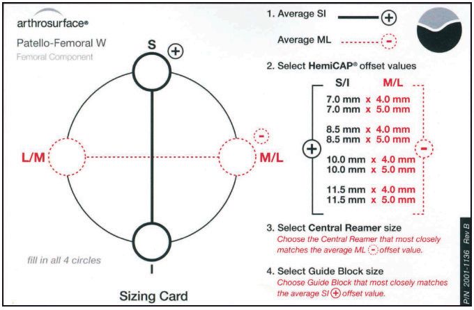
Chapter Two: HemiCAP PF W 29Instrumentation (HemiCAP® PF W)
QUICK CONNECT INNER CIRCULAR
DRIVER REAMERS (2) SCALPEL BUSHING
Upper Tray
DRILL
GUIDE CURRETTE
CONTACT GUIDE TEMPLATES OUTER
PROBE BLOCKS (4) REAMERS (2)
SIZING PLACEMENT STEP PATELLA
TRIALS (8) GAUGE DRILL CLAMP IMPACTOR
Lower Tray
SIZING TRIAL
HANDLE
HEX PILOT TAP SUCTION
DRIVER DRILL
Patella Caddy
25mm 30mm SIZING
REAMER REAMER TRIALS
30Warnings Precautions
Improper selection, placement, positioning, alignment, HemiCAP® Patello-Femoral Resurfacing implants are
and fixation of the implant components may reduce the intended to be fitted and installed with the HemiCAP®
service life of the prosthetic components. Inadequate Patello-Femoral Resurfacing instrument set. Use of
preparation and cleaning of the implant components instruments from other systems may result in improper
mating surfaces may result in improper fixation of the implant selection, fitting, and placement which could
device. Improper handling of the implants can produce result in implant failure or poor clinical outcome. The
scratches, nicks or dents that may have adverse clinical HemiCAP® instrument set should be regularly inspected
effects on mating joint surfaces. Do not modify implants. for any signs of wear or damage. Do not reuse implants
The surgeon shall be thoroughly familiar with the or disposable instruments.
implants, instruments, and surgical technique prior to
performing surgery. Possible Adverse Effects
When defining offsets of articular surfaces, care should 1) Material sensitivity reactions. Implantation of
be taken to ensure that instruments are properly aligned foreign material in tissues can result in histological
and mated with taper in Taper Post. Visually confirm reactions. Particulate wear debris and mild tissue
distal tip of contact probe is making contact on articular discoloration from metallic components have
surfaces and free from any soft tissue structures to ensure been noted in other prosthetic devices
accuracy. Use light pressure on contact probe to slightly constructed of similar materials. Some types of
indent articular surface at each offset point, ensuring wear debris have been associated with osteolysis
that the selected implant will be flush or slightly recessed and implant loosening.
with the articular surface.
2) Infection or allergic reaction.
Prior to placing implant, carefully trim articular cartilage
3) Loosening, migration or loss of fixation of
debris around prepared margin. Remove bone particles
implant.
and lavage thoroughly. To ensure mechanical interlock
of the Taper Post and implant, carefully clean Taper Post 4) Fretting and crevice corrosion can occur at the
taper with provided instruments. All drilling or reaming interface between the implant components.
should be done with vigorous lavage to minimize heat 5) Fatigue fracture of the implants as a result
effects to adjacent bone and cartilage tissues. of bone resorption around the implant
Accepted practices in post operative care should be components.
used. The patient is to be instructed and monitored 6) Wear and damage to the implant articulating
to ensure a reasonable degree of compliance to post surface.
operative instructions and activity restrictions. Excessive
activity, impact, and weight gain have been implicated in 7) Wear and damage to the adjacent and opposed
the reduction of the benefit and service life of prosthetic articular cartilage surfaces or soft tissue support
devices. structures.
8) Intraoperative or postoperative bone fracture.
31HemiCAP PF Classic Trochleas and Patellas
Anatomic
20 Button
HemiCAP W Trochleas and Patellas
Dome
Anatomic
Button
The Arthrosurface HemiCAP System is also available for the following joints:
• Shoulder • Unicompartmental
• Great Toe • Hip
• 2nd MTP • Femoral Condyle (Available in most
• Talus (Available in most International International markets via CE mark)
markets via CE mark)
This product is covered by one or more of U.S. Patent Nos. 6,520,964;
6,610,067; 6,679,917 and other patents pending.
HemiCAP® is a trademark of Arthrosurface, Inc. U.S. © 2012
Arthrosurface, Inc. All rights reserved.
Printed in U.S.A.
For more information, visit our website:
www.arthrosurface.com
28 Forge Parkway • Franklin, MA 02038
1 508 520 3003
fax: 1 508 528 4604 ISO 13485
This pamphlet and information is intended for markets where regulatory approval has been granted.
PN 2001-3210 REV BYou can also read