LIBERO SOC V2021.1 - MICROSEMI
←
→
Page content transcription
If your browser does not render page correctly, please read the page content below
Libero® SoC v2021.1
                                   SmartDesign User Guide

Introduction
SmartDesign is a visual block-based design creation and entry tool for the instantiation, configuration, and connection
of Microchip IPs, user-generated IPs, and custom and glue-logic HDL modules. This tool provides a canvas, which is
analogous to a breadboard, for stitching together the various design components. The final result from SmartDesign
is a design-rule-checked and automatically abstracted synthesis-ready HDL file. A generated SmartDesign can be
the entire FPGA design or a component subsystem to be reused in a larger design.
The following design objects can be instantiated in the SmartDesign Canvas:
  •   Microchip IP Cores
  •   User-generated or third-party IP Cores
  •   HDL design files
  •   HDL + design files
  •   Basic macros
                                                                                                 ®
  •   Other SmartDesign components (*.cxf files) generated from SmartDesign in the current Libero SoC project or
      imported from other Libero SoC projects
  •   Reusable design blocks (*.cxz files) published from Libero SoC
SmartDesign supports SmartFusion®2, IGLOO®2, RTG4™, PolarFire® and PolarFire® SoC devices.

© 2021 Microchip Technology Inc.                         User Guide                                DS50003075B-page 1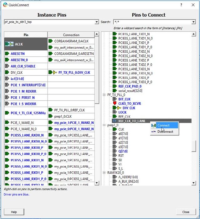
Libero® SoC v2021.1

Table of Contents
Introduction.....................................................................................................................................................1

1.    About SmartDesign................................................................................................................................. 4
      1.1.       Canvas Layout............................................................................................................................. 4
      1.2.       SmartDesign in the Libero SoC Design Flow............................................................................... 4
      1.3.       Instantiating Components into SmartDesign Canvas...................................................................5
      1.4.       SmartDesign Canvas and Component Display............................................................................ 6
      1.5.       SmartDesign Tcl Commands........................................................................................................7

2.    SmartDesign Icons, Hotkeys, and Menu Items....................................................................................... 8
      2.1.       SmartDesign Icons....................................................................................................................... 8
      2.2.       SmartDesign Hotkeys.................................................................................................................10
      2.3.       Click-and-Drag Operations......................................................................................................... 11

3.    SmartDesign User Actions.................................................................................................................... 14
      3.1.       Net Actions................................................................................................................................. 14
      3.2.       Instance Actions......................................................................................................................... 15
      3.3.       Pin/Port Actions..........................................................................................................................20
      3.4.       View Memory Map......................................................................................................................24

4.    Designing with SmartDesign................................................................................................................. 33
      4.1.       Create a Top-Level SmartDesign Component............................................................................33
      4.2.       Configure/Instantiate Components.............................................................................................34
      4.3.       Make the Connections................................................................................................................38
      4.4.       Add or Modify Top-Level Ports................................................................................................... 41
      4.5.       Invoke DRC on the Design.........................................................................................................42
      4.6.       Generate the Top-Level Component.......................................................................................... 42

5.    Design Navigation Features..................................................................................................................43
      5.1.       Expand and Fold Instance..........................................................................................................43
      5.2.       Magnify Pin.................................................................................................................................46
      5.3.       Go To Driver............................................................................................................................... 46

6.    Appendix A - FAQ................................................................................................................................. 47
      6.1.       General Questions..................................................................................................................... 47
      6.2.       Instantiating into your SmartDesign........................................................................................... 47
      6.3.       Working in SmartDesign.............................................................................................................47
      6.4.       Working With Processor-Based Designs in SmartDesign..........................................................47
      6.5.       VHDL Construct Support in SmartDesign.................................................................................. 47
      6.6.       Making the Design Look Nice.....................................................................................................48
      6.7.       Generating the Design............................................................................................................... 48
      6.8.       General Questions..................................................................................................................... 48
      6.9.       Instantiating Into Your SmartDesign...........................................................................................48
      6.10.      Working in SmartDesign.............................................................................................................49
      6.11.      Working with Processor-Based/AMBA-Bus Designs..................................................................50
      6.12.      VHDL Construct Support in SmartDesign.................................................................................. 51
      6.13.      Making the Design Look Nice.....................................................................................................53

© 2021 Microchip Technology Inc.                                                     User Guide                                                      DS50003075B-page 2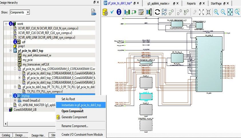
Libero® SoC v2021.1

      6.14. Generating the Design............................................................................................................... 53

7.    Appendix B - Glossary.......................................................................................................................... 55

8.    Appendix C - DRC Check..................................................................................................................... 57
      8.1.      Message Types and Corrective Actions..................................................................................... 57

9.    Revision History.................................................................................................................................... 59

10. Microchip FPGA Technical Support...................................................................................................... 60
      10.1.     Customer Service.......................................................................................................................60
      10.2.     Customer Technical Support...................................................................................................... 60
      10.3.     Website...................................................................................................................................... 60
      10.4.     Outside the U.S.......................................................................................................................... 60

The Microchip Website.................................................................................................................................61

Product Change Notification Service............................................................................................................61

Customer Support........................................................................................................................................ 61

Microchip Devices Code Protection Feature................................................................................................ 61

Legal Notice................................................................................................................................................. 62

Trademarks.................................................................................................................................................. 62

Quality Management System....................................................................................................................... 63

Worldwide Sales and Service.......................................................................................................................64

© 2021 Microchip Technology Inc.                                                    User Guide                                                     DS50003075B-page 3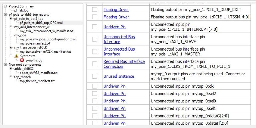
Libero® SoC v2021.1
                                                                                                  About SmartDesign

1.    About SmartDesign
      This section provides an overview of SmartDesign.

1.1   Canvas Layout
      The SmartDesign canvas places all components in columns, with the nets vertically routed in the space between
      columns. Top-level input ports are placed in the leftmost column. Top-level output ports and inout ports are placed in
      the rightmost column.
      Components can be moved up and down the columns. When components are instantiated in SmartDesign, they are
      placed in an existing column or a new column created for them. When components are moved up and down, the
      column boundaries are shown. When components are moved horizontally, the instance can be moved to a different
      column, the column it is in can be moved, or a new column can be created at the new location for the instance.
      The following figure shows the SmartDesign canvas.
      Figure 1-1. SmartDesign Canvas

1.2   SmartDesign in the Libero SoC Design Flow
      SmartDesign allows you to stitch together HDL, IPs, re-usable design blocks, lower level SmartDesign blocks, and
      other design blocks of different types, and generate a top-level design. The Files tab lists your SmartDesign files in
      alphabetical order.
      To build your design, perform the following procedure:
        1. Instantiating components: This step is analogous to inserting design components onto the breadboard. In
             this step you add one or more building blocks, HDL modules, components, and schematic modules from the
             Project Manager to your design. The components can be design blocks, IP cores from the Catalog, basic
             macros, design blocks (*.cxz), and other SmartDesign components (.cxf) file imported into the Libero SoC
             project.
        2. Connecting bus interfaces: In this step, you can add connectivity via standard bus interfaces to your design.
             This step is optional and can be skipped if you prefer manual connections. Components generated from the
             Catalog may include predefined interfaces that allow for automatic connectivity and design rule checking when
             used in a design.

      © 2021 Microchip Technology Inc.                          User Guide                                 DS50003075B-page 4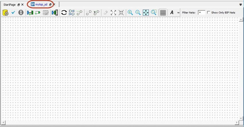
Libero® SoC v2021.1
                                                                                                   About SmartDesign

        3.    Connecting instances: The Canvas allows you to create manual connections between ports of the instances
              in your design. Unused ports can be tied off to GND or VCC (disabled); input buses can be tied to a constant,
              and you can leave an output open by marking it as unused.
        4.    Generating the SmartDesign component: In this step, you generate a top-level (Top) component and its
              corresponding HDL file. This component can be used by downstream processes, such as synthesis and
              simulation, or you can add your SmartDesign HDL into another SmartDesign. When you generate your
              SmartDesign, the tool invokes the Design Rules Checker to verify the connectivity of your design. Undriven
              and floating ports, along with other Design Rule Check (DRC) violations, are reported in the Log/Message
              window. Any error messages must be addressed before a component can be generated successfully. The
              design flow cannot proceed if component generation fails.

1.3   Instantiating Components into SmartDesign Canvas
      For all the following design objects, drag-and-drop or right-click object > Instantiate to instantiate the design objects:
        •    IP cores—To instantiate IP cores, drag the IP core from the Catalog into the SmartDesign Canvas. Configure the
             IP cores in the IP Core Configurator before it can be dropped in the SmartDesign Canvas. IP cores displayed in
             the Catalog as italics are cores that are available in Microchip IP Core Repositories, but are not yet downloaded
             to the vault (the disk location where downloaded cores are stored). Download the IP core prior to configuration
             and instantiation.
        •    HDL files—To instantiate HDL design blocks, drag the HDL design file from the Design Hierarchy into the
             SmartDesign Canvas.
        •    HDL+ cores—HDL+ cores are HDL files where the parameters and generics are used and a core has been
             generated out of it (right-click HDL file > Create Core from HDL). Drag and drop the HDL+ module into
             the SmartDesign canvas. The HDL core becomes configurable inside the SmartDesign canvas. Open the
             configurator to set the values for the parameters and generics. An interface bus may also be added to the HDL+
             core, and it will show up in the SmartDesign with a bus interface pin that can be used to easily connect to the
             appropriate bus IP Core inside SmartDesign Canvas.
        •    Re-usable Design Blocks (*.cxz) file—Drag and drop the design blocks (*.cxz) from the Design Hierarchy into
             the SmartDesign canvas. Design blocks are components that may have completed layout in a different Libero
             SoC project and exported/published, to be ready for re-use in a higher level design as a component. The design
             blocks must be imported into the current Libero SoC project to be instantiated in SmartDesign. The following
             figure shows how to instantiate a design block.
             Figure 1-2. Design Block (*.cxz) Instantiation

        •    SmartDesign Components—Another SmartDesign component (*.cxf) can be instantiated in the SmartDesign.
             Drag and drop the Smart Design component (*.cxf) from the Design Hierarchy into the SmartDesign canvas.
             Instantiation can also be done by right-clicking the (top) module name in the Design Hierarchy and choosing

      © 2021 Microchip Technology Inc.                          User Guide                                  DS50003075B-page 5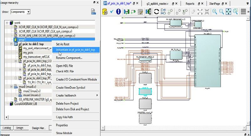
Libero® SoC v2021.1
                                                                                               About SmartDesign

           Instantiate. The component (*.cxf) and its corresponding HDL files and IP cores must be imported into the
           current project and configured before instantiating in the new SmartDesign project.
      Figure 1-3. SmartDesign Component (*.cxf) Instantiation

1.4   SmartDesign Canvas and Component Display
      The SmartDesign Canvas window can be docked/undocked by clicking the         icon. The canvas displays different
      component types with different colors. When the mouse is hovered over the component, a tooltip displays the type
      and name of the component. For IP Cores, the core version is also displayed.
      The following table lists the component types and their appearance in the SmartDesign canvas.
      Table 1-1. Component Type and Name in Canvas

       Graphic Display              Component Type           Tooltip Information
                                    IP Cores from Catalog    Core: COREAXI4SRAM 2.1.105

                                    Basic Macros/Macro       Macro: NAND4
                                    Library from Catalog

                                    Re-usable Design Blocks Block: prep1
                                    (*.cxz file) imported into
                                    Libero SoC project

                                    SmartDesign              SmartDesign: adder_shift32
                                    Components (*.cxf file)
                                    imported into Libero SoC
                                    project

      © 2021 Microchip Technology Inc.                        User Guide                               DS50003075B-page 6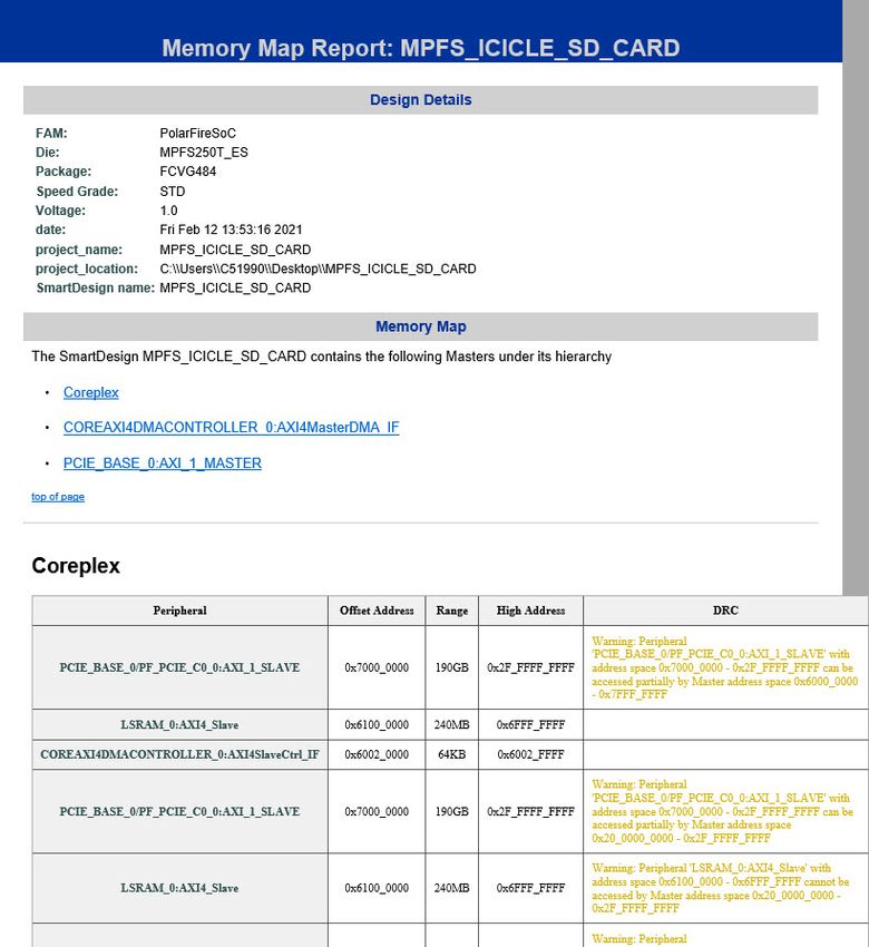
Libero® SoC v2021.1
                                                                                          About SmartDesign

      ...........continued
       Graphic Display              Component Type         Tooltip Information
                                    Design HDL file imported HDL: mux2
                                    into Libero SoC project

                                    Core generated from    HDL+: mux4
                                    HDL

1.5   SmartDesign Tcl Commands
      For details about the Tcl commands supported by SmartDesign, refer to the SmartFusion2, IGLOO2, RTG4 Tcl
      Commands Reference Guide or the PolarFire FPGA Tcl Commands Reference Guide.

      © 2021 Microchip Technology Inc.                       User Guide                           DS50003075B-page 7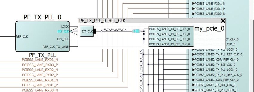
Libero® SoC v2021.1
                                                            SmartDesign Icons, Hotkeys, and Menu Items

2.    SmartDesign Icons, Hotkeys, and Menu Items
      This section describes the SmartDesign icons, hotkeys, and menu items.

2.1   SmartDesign Icons
      Across the top of the SmartDesign canvas is a list of icons. Use the icons to:
        •   Make connections
        •   Control the canvas display
        •   Invoke Design Rule Check
        •   Generate the HDL for the component
        •   Adding Text
        •   Save the SmartDesign to PDF
      The following table lists the SmartDesign icons. Tooltips are provided for each icon. Hover the mouse over the icon to
      display the tool-tips.
      Table 2-1. SmartDesign Icons

       Icon               Action/Tooltip                Description
                          Generate Component            Generates the design. Converts the visual design you create
                                                        into an HDL file for use in the project if there are no errors in
                                                        the design. This action implicitly and automatically invokes the
                                                        Design Rule check. DRC Error messages are generated in the
                                                        Log/Message window. A DRC report is also generated (Design
                                                        > Reports > _DRC.xml).Clicking
                                                        this button affects the design state.
                          Design Rule Check             Invokes the Design Rule Checker (DRC). If the design is not
                                                        valid (DRC violations), then errors appear in the Log/Message
                                                        window. A DRC report is also generated (Design > Reports
                                                        > _DRC.xml). No HDL file is
                                                        generated even if the DRC check passes. Clicking this button
                                                        does not affect the design state. To generate the HDL for the
                                                        component, click the Generate Component button.
                          Toggle Highlighting           Click this icon to highlight any instances on the canvas that have
                          Instances with Status         status information for the instance (for example, “A new version
                          Message                       is available”). Hovering the mouse over an instance opens a
                                                        tooltip to display the info/message (for example, “A new version
                                                        is available”). Click this icon if you have made any changes to
                                                        a component, reconfigured a core or have downloaded newer
                                                        versions of the core used in the design.
                          Add Port                      Add a new top-level port to the design. A pop-up window appears
                                                        for you to enter the name of the port and the directions (Input/
                                                        Output/Inout). Input Ports are added in the leftmost column of
                                                        the canvas. Output and Inout ports are added in the rightmost
                                                        column. After the port is added, hover the mouse over the input
                                                        port to display the port name, direction and fanout. Hover the
                                                        mouse over the output port to display the port name, direction and
                                                        drivers of output port. Bus ports can also be added. For example:
                                                        myInputBus[7:0]
                                                        Alternatively, right-click on empty space inside the canvas and
                                                        choose Add Port. A port is added in the canvas and is anchored at
                                                        the Y coordinates of cursor. See the figure below.

      © 2021 Microchip Technology Inc.                         User Guide                                 DS50003075B-page 8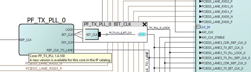
Libero® SoC v2021.1
                                                  SmartDesign Icons, Hotkeys, and Menu Items

...........continued
 Icon                  Action/Tooltip         Description
                       View                   Click this icon to open the View Memory Map dialog which
                                              shows the memory map corresponding to various masters in the
                       Memory Map
                                              SmartDesign component in a hierarchical tree format. This dialog
                                              box shows the memory map starting from a master in the design to
                                              peripherals connected through bus and bridge cores hierarchically.
                                              Each peripheral in the memory map is shown with a Start Address,
                                              Range and DRC.

                       QuickConnect           Opens a dialog that helps you make connections more quickly.
                                              This dialog lists the pins in the design, and allows you to select
                                              multiple pins and make a connection directly.
                       Reset Layout           Click to reset the layout view. Clicking this button removes all
                                              presentation information (position, size, highlights, modified pin
                                              orders).
                       Auto-arrange Layout    Click to redo the layout of where components are placed on the
                                              screen. Only the location (x-y coordinates) of the instances and
                                              ports are changed. All presentation information remains intact.
                       Compress Layout        Click to push the instances and ports towards each other in order
                                              to remove extra white space between them on the screen. The
                                              relative positions of the instances on the screen are preserved. The
                                              result is a more compact display of the design.
                       Hide Nets              Toggle button. Click to hide nets and make them invisible on
                                              the canvas. All nets on the canvas are hidden. This button has
                                              precedence over net filtering and over-rides all net filters. To hide
                                              some but not all nets, do not use this button. Use the Filter Net
                                              widget at the rightmost of the toolbar.
                                              Hiding nets also hides the net names (if present). When a net is
                                              hidden, the net stubs that the hidden net is connected to are still
                                              visible. Selecting the net stubs shows the RATS net connection of
                                              the net.

                       Show Nets              Toggle button. Click to show/hide nets. All nets on the canvas are
                                              shown/hidden.
                                              If nets are shown, all nets matching the net filter (at the far right of
                                              toolbar) are shown.

                       Show/Hide Net Names    Toggle button. Click to show net name displayed alongside the net.
                                              Hiding net names makes the canvas less cluttered for big designs.
                                              Net names are always displayed in a tooltip when the mouse is
                                              hovered above the net.

                       Unhighlighted All      Remove all highlighting of all design objects (nets, pins, ports,
                                              instances) on the canvas. This option is highlighted only if design
                                              objects are already highlighted.
                       Expand All Instances   Expand (display the hierarchy to the lowest level) in place of all
                                              instances in the canvas.

                       Fold All Instances     Collapse the hierarchy of all expanded instances into the top-level
                                              hierarchy.

© 2021 Microchip Technology Inc.                     User Guide                                    DS50003075B-page 9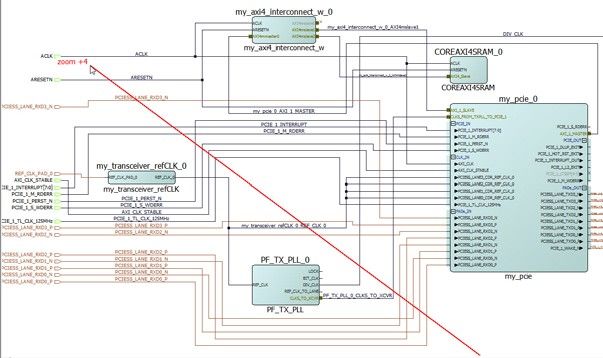
Libero® SoC v2021.1
                                                               SmartDesign Icons, Hotkeys, and Menu Items

      ...........continued
       Icon                  Action/Tooltip                 Description
                             Zoom In                        Zoom in on the canvas.

                             Zoom Out                       Zoom out off the canvas.

                             Zoom to Fit                    Adjust the zoom so that everything on the canvas just fits inside of
                                                            the visible viewport with no extra empty space around the design.

                             Zoom to Selection              Click this icon and drag the mouse to draw a rectangle which when
                                                            released causes a zoom in so that the visible viewport area is
                                                            approximately the size of the drawn rectangle.

                             Show Grid                      Click to show a background grid behind the items on the canvas.
                                                            If the grid does not appear when the button is clicked, zoom in
                                                            until the grid shows. The grid pattern may not show if the canvas is
                                                            zoomed too far out.
                             Add Note                       Click to enter the Add Note mode. The next mouse click on the
                                                            canvas opens a dialog box for entering the text and font size for the
                                                            text (anchored at the mouse click location).

                             Save to PDF                    Click this icon to bring display a dialog that allows you to save a
                                                            picture of all/part of the design to a PDF document.

      Figure 2-1. Add Port Dialog Box

2.2   SmartDesign Hotkeys
      The following table lists the Hotkeys available in the SmartDesign canvas.
      Table 2-2. SmartDesign Hotkeys

       Hotkey                                 Description
       CTRL + w                               Maximize the canvas work area.
       CTRL + f                               Open the Find dialog box.

      © 2021 Microchip Technology Inc.                             User Guide                                 DS50003075B-page 10
Libero® SoC v2021.1
SmartDesign Icons, Hotkeys, and Menu Items
...........continued
Hotkey Description
CTRL + +/CTRL + = Zoom in (same as clicking the Zoom In button in toolbar or pressing CTRL+
scroll wheel up mouse)
CTRL + - Zoom out (same as clicking the Zoom Out button in toolbar or pressing CTRL +
mouse scroll wheel down)
CTRL + c Clear the clipboard. If a single instance is selected before the Hotkey, it is
added to the clipboard. The display name of the design object is also copied.
CTRL + v If the copy information of a single instance is in the clipboard then call clone
instance on it. For details, see Help.
CTRL + z Undoes the last operation.
CTRL + y Redoes the last operation.
SHIFT + click Click one item and SHIFT + click another item. The first clicked item, the second
clicked item and all items of the same type between the first and second
clicks are selected. This command is helpful when multiple items needed to
be selected for the same command (promotion to top-level/Add to group).
CTRL + click Control + click is a toggle switch that selects or de-selects an item under the
mouse cursor.
CTRL+SHIFT+click and then drag Selects a pin of an instance and drag the mouse to a new location to move
the pin of the instance. This is not available for macros and expanded in place
instances.
2.3 Click-and-Drag Operations
The following table lists the mouse click-and-drag operations available in the SmartDesign canvas.
Table 2-3. Mouse Click-and-Drag Actions
Mouse Actions Description
Left-click and drag towards the Zoom in. The distance of the mouse travel determines the magnitude of the
top-left corner, and then release. zoom-in and is indicated by a positive integer in red. See the figure below.
Left-click and drag towards Zoom out. The distance of the mouse travel determines the magnitude of the
the top-right corner, and then zoom- out and is indicated by a negative integer in red. See the figure below.
release.
Left-click and drag towards Zoom to fit. Change the display to fit the canvas view area snugly.
bottom left, and then release
Left-click and drag toward bottom Draw a rectangle on the canvas. Instances, pins and ports must be fully
right, and then release contained inside the rectangle to be selected. Nets partially inside the rectangle
are selected.
© 2021 Microchip Technology Inc. User Guide DS50003075B-page 11Libero® SoC v2021.1
SmartDesign Icons, Hotkeys, and Menu Items
Figure 2-2. Example of Zoom In
© 2021 Microchip Technology Inc. User Guide DS50003075B-page 12Libero® SoC v2021.1
SmartDesign Icons, Hotkeys, and Menu Items
Figure 2-3. Example of Zoom Out
© 2021 Microchip Technology Inc. User Guide DS50003075B-page 13Libero® SoC v2021.1
SmartDesign User Actions
3. SmartDesign User Actions
The SmartDesign tool has a rich set of menu items, accessible from the right-click menu of a selected design object,
for you to:
• Make connections between design objects
• Rename design objects
• Highlight design objects
• Traverse up/down the hierarchy of instances
• Assign attributes of pins/nets/buses.
The list of available user actions varies with the design object. Some actions are common to all objects, while other
actions are unique to a design object (net/instances/pins/ports).
3.1 Net Actions
When a net or multiple nets are selected, the following actions are available in the right-click menu item.
3.1.1 Connect
This action combines with all selected pins/ports to form a connection. Selecting a net is functionally equivalent to
selecting all pins and ports to which this net is connected. This action can also be used to connect a net to another
net if one of the net is not driven.
3.1.2 Go to Driver
When a net is selected, the Go to Driver action centers the view on the net’s driver pin/port, zooms away, and then
selects the net driver. The driver must be an input port/output pin. It cannot be an inout pin/port. This action is not
available when multiple nets are selected or the selected net has no driver. Go to Driver traces the net to the driver at
the local level of hierarchy. It does not traverse hierarchy.
3.1.3 Highlight
Right-clicking a design object (nets/pins/ports/bus interface/instance) menu opens a menu of colors for highlighting.
Clicking a color selects that color to highlight the selected design objects. If any design objects are already
highlighted then highlighting a different color will overwrite the previous highlight color. The highlight action is
available when a single or multiple design objects are selected.
Note: Highlighting a net highlights the net and all the pins/ports (through the hierarchy) connected to the net.
© 2021 Microchip Technology Inc. User Guide DS50003075B-page 14Libero® SoC v2021.1
SmartDesign User Actions
Figure 3-1. Highlight Colors
To remove the highlight on a single design object, right click the design object and select Remove Highlight.
To remove all highlighted design objects, click the Unhighlighted All icon in the toolbar.
3.1.4 Rename
The rename action opens a dialog for a new net name to be entered to replace the old name. Clicking OK changes
the net name to the new net name if it is valid (e.g., not already used). Clicking OK prints an error in the Log window
and the dialog does not close if the name already exists or is invalid.
3.1.5 Delete
Deletes the net. Net names, if shown, are also deleted.
3.2 Instance Actions
When one or more instances are selected, the following actions are available in the right-click menu.
3.2.1 Configure
If the instance is a SmartDesign component, the Configure action opens the SmartDesign canvas for edits. If the
selected instance is an IP Core, the Configure button opens the Configurator dialog for the core to be configured. If
the selected instance is an HDL, the configure action opens the HDL file in the text editor. This action is equivalent to
double-clicking the instance. This action is available only when one single instances is selected.
This action is also available in the right-click menu of low-level instances in the Expanded Inplace view.
3.2.2 Modify HDL
This action opens the instance’s HDL source file in the text editor. Available only when an instance of an HDL+
component is selected.
Note: If the component is an HDL file, this option is not available. To open an HDL file, double-click the HDL
component on the SmartDesign canvas or right-click the HDL component and choose Configure.
© 2021 Microchip Technology Inc. User Guide DS50003075B-page 15Libero® SoC v2021.1
SmartDesign User Actions
3.2.3 Highlight
This action opens a menu with multiple highlight color selections. Clicking that color selects that color to highlight
the selected items. If any items are already highlighted then highlighting a different color will overwrite the previous
highlight color. The action is available when a single or multiple nets are selected.
Highlighting an instance automatically highlights the non-highlighted pins of the instance as well. Clicking the
Unhighlight all icon in the toolbar removes the highlight color of all highlighted design objects, including
highlighted nets.
This action is also available in the right-click menu of low-level instances in the Expanded Inplace view.
3.2.4 Rename
This action opens the rename dialog for a new instance name to be entered. If the instance name is valid, clicking
OK changes the instance to this name, and then closes the dialog.
If the instance name is not valid or already exists, clicking OK prints an error in the Log window, displays a warning
message, and will not close.
3.2.5 Copy and Paste
Copy and Paste are used to copy instance to the clipboard and paste the copied instance on the canvas.
The copy action is also available in the right-click menu of low-level instances in the Expanded Inplace view.
Copying an IP Core on the canvas copies into the clipboard the following:
• The configuration of the core
• Pin attributes (Tie high/low/Mark Unused/Inverted)
• Name of the instance
• The input pin connections are available only if pasted inside the same SmartDesign component
• Presentation Information (e.g., Highlighting, size, pin order) is available only if pasted inside the same
SmartDesign component.
Note: If a change is made to the instance after the copy, but before the paste command, the paste command uses
the most current version of the instance, not the version at the time of copy. Copying from another Libero SoC project
is not supported.
3.2.6 Delete
This action deletes the selected item. When multiple items are selected, all are deleted.
Note: Not all design objects can be deleted. Pad ports cannot be deleted.
3.2.7 Expand Inplace and Fold Instance
The Expand Inplace action is equivalent to clicking the + (Expand) sign in the top-left corner of the instance. It causes
the selected instance to expand (to expose all levels of hierarchy) in place if not expanded. It is available to all
instances at all levels of hierarchy except the lowest level. If only one instance is selected, the viewport will zoom to
the instance after the expand or fold is completed. This action is for SmartDesign components and is read-only. No
changes can be made to the expanded hierarchy. Changes to the components at the lower level of hierarchy must be
made by opening the low-level component directly. For more information, see Expand and Fold Instance.
© 2021 Microchip Technology Inc. User Guide DS50003075B-page 16Libero® SoC v2021.1
SmartDesign User Actions
Figure 3-2. Expand Inplace
The Fold Instance action is a toggle switch. It is equivalent to clicking the - (Fold) sign of an expanded instance. It
causes the expanded hierarchy of the instance to collapse to the top level.
Figure 3-3. Fold Instance
3.2.8 Replace Component
This action displays the Replace Component for Instance(s) dialog. Selecting an instance and then clicking OK
replaces every instance of that component in the current design with an instance of the new component if that
component is valid. All pins that have the same name on the new component will keep their connections, whereas
pins that no longer exist will lose their connection and a warning will be printed in the Log window. The dialog will
then close.
Selecting an instance and then clicking OK for a non-valid component will close the dialog and print an error in the
Log window
© 2021 Microchip Technology Inc. User Guide DS50003075B-page 17Libero® SoC v2021.1
SmartDesign User Actions
Figure 3-4. Replace Component Dialog
3.2.9 Update Component
This action updates all instances of that component in the current SmartDesign with the newest version of that
component. This is available only when the port list has changed. Changing the port list of an instance causes it to
return to a new default size.
3.2.10 Replace Component Version
This action exists for IP cores. Under Design Hierarchy, select an IP core, right-click, and choose Replace
Component Version. The Replace Component Version dialog appears.
Figure 3-5. Replace Component Version Dialog
Changing the version in the dialog and then clicking OK changes all instances of that component in the current
SmartDesign canvas to the specified version of that component.
3.2.11 Modify Pin Order
This a toggle switch. Right-click an instance to open the drop-down menu. Select Modify Pin Order. A pop-up
window provides instructions on how to reset pin order. Press CTRL+SHIFT and click to select the pin you want to
move.
© 2021 Microchip Technology Inc. User Guide DS50003075B-page 18Libero® SoC v2021.1
SmartDesign User Actions
Figure 3-6. Modify Pin Order
Drag the mouse to a new location and release the mouse. The pin is moved to a new location. By default, input pins
are on the left of the instance while output pins/inout pins are on the right. Modify Pin Order allows you to place the
pins on any one of the four sides of the instance. A pin that has been moved away from default locations is identified
by a bold arrow head. An inward-pointing arrow head indicates an input pin and an outward-pointing arrow head
indicates an output pin. Inout pins do not have an arrow head when they are moved away from the default locations
(right side of instance).
Note: If there are two instances on the canvas that communicate with each other in a way where the outputs of one
component instance A communicates with the inputs of another component instance B and vice versa, modifying the
pin order gives a less cluttered view of the SmartDesign component. See Modify Pin Order Before Connections for
details.
Note: Modify Pin Order is disabled when the instance is expanded in place. The modified pin order may not be
preserved when an instance is expanded but will retain the set order when folded.
3.2.12 Reset Pin Order
This is a toggle switch. Reset pin order reverses modifications and resets the pins to the default location.
If you moved an instances pin order, this action unresizes the instance and reloads the order from the SmartDesign
model.
Note: If you move a pin, and then move it back to its original position, reset pin order will be enabled, but will only
resize.
Figure 3-7. Modify/Reset Pin Order
3.2.13 Remove Connections
This action disconnects all pins that can be disconnected. Pins that cannot be disconnected (for example pins
connected to pads) are logged in the Log window.
© 2021 Microchip Technology Inc. User Guide DS50003075B-page 19Libero® SoC v2021.1
SmartDesign User Actions
3.2.14 Help
Opens the handbook, release notes, or configuration user guides for the core.
3.3 Pin/Port Actions
Right-click a pin or a port and the drop-down menu appears. Not all actions appear for every port/pin.
3.3.1 Connect
The Connect action adds a net to the design that connects the selected pins/ports. This is the only pin/port action that
takes selected nets into account. Selecting a net works as if you selected all of the nets connected pins/ports.
3.3.2 Disconnect
This action disconnects all selected non-pad pins/ports from their attached net if it is allowed (not violating the DRC
rules).
3.3.3 Promote to Top Level
This option is available to input/output/inout pins (scalar and bus), slices, and Bus Interfaces (BIF). It creates a
top-level port and a net connecting the top-level port to the pin or slices. If a port with that name already exists, a new
unique port name is created.
3.3.4 Go to Driver
This action centers on, zoom around, and selects the driver of the pin/port. This action is not available for output pins
and top-level input ports. The driver cannot be an inout.
3.3.5 Magnify Pin
This action opens the Magnify window to display connection information (driver/load) about the pin. It is equivalent to
double-clicking the pin.
Figure 3-8. Magnify Pin Window
See Magnify Pin for details.
3.3.6 Highlight
This action opens a menu with multiple highlight color selections. Clicking that color selects that color to highlight
the selected items. If any items are already highlighted then highlighting a different color will overwrite the previous
highlight color. The action is available when a single or multiple pins/ports are selected.
Clicking the Unhighlight all icon in the toolbar removes the highlight color of all highlighted design objects,
including highlighted pin/ports.
3.3.7 Modify and Rename
This action opens a Modify Port dialog. It allows the top-level port name and the range to be changed.
© 2021 Microchip Technology Inc. User Guide DS50003075B-page 20Libero® SoC v2021.1
SmartDesign User Actions
Figure 3-9. Modify/Rename Dialog
3.3.8 Delete
This action deletes all selected items that can be deleted: slices, groups, group members, top-level ports.
The delete action deletes all items selected, even if the selected items are of different types. When a group member
is deleted, the member is deleted from the group only. The actual pin is not deleted.
3.3.9 Expanding and Collapsing Bus
Expanding a bus displays the slices of the bus and collapsing the bus hides the slices. Slices with net connections
cannot be hidden and cannot be collapsed into the bus.
3.3.10 Flip Bit Order
This option is available only to slices. It allows you to flip the upper range (MSB) and lower range (LSB) of the slice.
All connection/tieoff information and presentation information are retained.
3.3.11 Create Slices
Open a menu of slice options that can be created from the bus pin/ports. A custom slice option to create any slice/bit
combination of your choice and the more common possible combinations of slices are available. For example, using
a 32-bit bus with the Custom Slices option allows the creation of any slice/bit combinations (e.g., a slice of 10 bits
and another slice of 22 bits). To make it convenient to create slices, common, off-the-shelf bus slices are listed in the
drop-down menu; for example:
• 32 slices of width 1
• 16 slices of width 2
• 8 slices of width 4
• 4 slices of width 8
• 2 slices of width 16
Figure 3-10. Slice Creation for a 32-bit Bus
On a components bus pin the slices will be expanded by default.
The directions of the slices (input/out) are indicated by an arrow head.
© 2021 Microchip Technology Inc. User Guide DS50003075B-page 21Libero® SoC v2021.1
SmartDesign User Actions
On a top-level bus port the slices will be placed in a column below the bus port.
Note: If slices exist before new off-the-shelf slices are created, the existing slices are deleted first before new ones
are created.
3.3.12 Custom Slices
This option opens a dialog for entering a list of slices. If these slices are all valid then they are added to the bus. If
the slices are not valid (e.g., slice bits already exist and used in an existing slice), the error is reported in the Log
window. The dialog supports any separator character except colon because the colon is used to specify a range. No
characters other than the colon is allowed adjacent to the two range indices.
Note: Creating a custom slice does not delete pre-existing slices.
Figure 3-11. Custom Slices Dialog
3.3.13 Edit Slices
The Edit Slice option opens the Edit Slices dialog. It allows existing slices to be modified.
Figure 3-12. Edit Slices Dialog
Use the dialog to change the range of the bits, add a slice or delete a slice. Modifying the slices and clicking OK
initiates the changes if they are valid and closes the dialog.
Modifying the slices and clicking OK prints an error in the Log and closes the dialog if the changes are not valid.
Some error messages may be reported in the Edit Slice dialog. Hover the mouse over the error icon to display details
of the error.
© 2021 Microchip Technology Inc. User Guide DS50003075B-page 22Libero® SoC v2021.1
SmartDesign User Actions
Figure 3-13. Tooltip and Error Message
3.3.14 Clear Attributes
This action clears the pin attributes (Tie to High/Low/Constant, Inversion/Marked Unused).
3.3.15 Mark Unused
This is available to the output pins (scalar and bus) of a component instance. This action specifies the pin/port as
unused so it can pass DRC check without being connected.
3.3.16 Invert
This action inverts the input/output scalar pin and port. A bubble is added to indicate inversion.
3.3.17 Tie High and Tie Low
The Tie High action connects the pin (scalar and bus) to VCC. For a bus pin this action deletes all slices. For a group
this action is applied to all non-output member pins in the group.
The Tie Low action connects the pin (scalar and bus) to Ground. For a bus pin this action deletes all slices. For a
group this action is applied to all non-output member pins in the group.
3.3.18 Tie Constant
This action is available only to bus pins and slices (except single-bit slice). It opens the Tie to Constant dialog box
for a constant value in HEX to be entered for the bus pins and slices. Only valid values entered in HEX within
parenthesis are allowed.
Figure 3-14. Tie to Constant Dialog
3.3.19 Add Pin to New Group and Add Pin to Group
This menu item is available to instance pins. If a group is selected first, right-click a pin and choose Add Pin to
Group to add the pin to the selected group. If no group is selected first, the menu item is called Add Pin to New
Group, a new group with the default group name Group/Group_1/Group_2/Group_3/ and so on is created, and all
selected pins are added to the newly created group.
A pin group can be expanded to display the member pins or collapsed to hide the member pins. Member pins
connected to nets cannot be hidden and cannot be collapsed into the group. Only member pins (in a pin group) with
Pin Attributes (Tie high/low/marked unused) can be hidden and collapsed into the pin group.
© 2021 Microchip Technology Inc. User Guide DS50003075B-page 23Libero® SoC v2021.1
SmartDesign User Actions
3.3.20 Rename (Group)
This is available only to group pins. It opens the Rename Group dialog for the group name to be changed. If a valid
name is entered then clicking OK renames the group. The new name field defaults to the current group name if no
new name is entered in the dialog.
If an invalid name is entered or a pin with that name already exists then clicking OK prints an error in the Log and
closes the dialog.
3.3.21 Show and Hide BIF Pins
This opens the Show Pins to Expose dialog to display all the Bus Interface Pins available to be exposed or hidden
from the instance. Check the pins in the BIF you want to expose and uncheck the pins you want to hide. Hidden pins
will not be exposed on the interface.
Note: Not all pins can be exposed. The pins that can be exposed depends on the BIF. If the BIF is connected
already, then none of the input pins can be exposed. If the BIF is not connected, every item in the menu can be
exposed.
Figure 3-15. Show to Expose Dialog
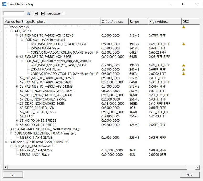
3.4 View Memory Map
The View Memory Map dialog constructs the memory map corresponding to various masters in the SmartDesign
component and displays the hierarchy in a tree format. To open the dialog box, right-click anywhere on the
SmartDesign canvas and select View Memory Map. Alternatively, right-click on any bus core instance in the canvas
and select View Memory Map, or click the View Memory Map icon in the toolbar at the top of the canvas .
Figure 3-16. View Memory Map Dialog Box
© 2021 Microchip Technology Inc. User Guide DS50003075B-page 24Libero® SoC v2021.1
SmartDesign User Actions
This dialog box shows the memory map starting from a master in the design to peripherals connected through bus
and bridge cores hierarchically. There can be various types of bus and bridge cores in the hierarchy between the
master and the peripherals.
• Master Node -> Parent Bus -> Bridge -> Child Bus -> Peripherals
• Master Node - > Bus -> Peripherals
Note: The memory map dialog box also considers masters, bus and bridge cores, and peripherals that are present in
other SmartDesign components, which are instantiated under the current SmartDesign’s hierarchy.
Each peripheral in the memory map is shown with an Offset Address, Range, High Address and DRC. If DRC exists,
an Error/Warning icon with a tooltip message will be shown. DRC is flagged if a peripheral cannot be accessed
completely or partially by the master’s address space.
Downgrade memory map generation Design Rule Check(DRC) errors to warnings Option has been added to
downgrade DRC errors to warnings while generating a Memory Map report. You can access this option by clicking on
Project > Preferences > SmartDesign.
Figure 3-17. Downgrade memory map generation Design Rule Check(DRC) errors to warnings option in
Preferences Dialog Box
© 2021 Microchip Technology Inc. User Guide DS50003075B-page 25Libero® SoC v2021.1
SmartDesign User Actions
Note:
In PolarFire SoC MSS based designs, the Fabric Interface Controllers(FICs) FIC_0 and FIC_1 have two regions
each, 64GB and 512MB. A peripheral accessible by the Coreplex via one FIC region may not be accessible in the
other FIC region based on the address spaces and bus configurations. This is a valid design scenario and should
not be flagged as an error in the Memory Map DRC section. So a Memory Map DRC error that is seen in both the
regions (64GB and 512MB regions) of a FIC will stay as an error, and if the DRC error is seen only in one of the
two regions of the FIC, then it will be automatically downgraded to a DRC warning, both in the Memory Map and
SmartDesign component generation.
Navigation buttons and filters
The View Memory Map dialog also provides new buttons and filters at the top of the dialog box for easy navigation
and ease of use.
Figure 3-18. View Memory Map Dialog Buttons and Filters
• Search button
You can search for a specific master/bus/bridge/peripheral in the memory map by specifying a full or partial
name in the search text box.
• Expand all button
Expands and shows the full hierarchy of all masters in the memory map starting from the master to the
peripherals.
• Collapse all button
Collapses the full hierarchy of all masters in the memory map and only shows the top-level masters in the
dialog.
• Show Slaves filter
Shows all the masters and the peripherals under them in the design in a flat hierarchy with their start addresses,
ranges and DRCs if any. The bus and bridge cores will not be shown.
© 2021 Microchip Technology Inc. User Guide DS50003075B-page 26Libero® SoC v2021.1
SmartDesign User Actions
Exporting Memory Map Report
The View Memory Map dialog contents can be exported to a memory map report file of .json or .html format. Select
the Memory Map Report option from Libero File -> Export. In the Export Memory Map Report dialog, you can specify
the SmartDesign component for which you want to export the memory report. Click on the Browse button in the
dialog to specify the memory map report file name, type (.json or .html) and location on disk. A .json or .html format
memory map report file (which can be opened in a web browser or a json viewer in a text editor) will be created when
you click the Save button.
Figure 3-19. Libero Option to Export Memory Map Report
Figure 3-20. Export Memory Map Dialog Box (.json format)
Figure 3-21. Export Memory Map Dialog Box (.html format)
© 2021 Microchip Technology Inc. User Guide DS50003075B-page 27Libero® SoC v2021.1
SmartDesign User Actions
Figure 3-22. Sample Memory Map Report (.json format)
Figure 3-23. Sample Memory Map Report (.html format)
© 2021 Microchip Technology Inc. User Guide DS50003075B-page 28Libero® SoC v2021.1
SmartDesign User Actions
Masters, Bus and Bridge cores available in Libero SoC Catalog
Various types of cores recognized as masters, and bus and bridge cores are available in the Libero SoC Catalog
window that can be used in a design. There are a few limitations on some of the core versions that can be used in
a design for the memory map to be constructed correctly in the View Memory Map dialog. The below consolidated
table of all the available masters, and bus and bridge cores highlights those limitations/exceptions on the cores and
core versions w.r.t memory map.
© 2021 Microchip Technology Inc. User Guide DS50003075B-page 29Libero® SoC v2021.1
SmartDesign User Actions
Table 3-1. Masters, Bus and Bridge cores available in Libero SoC Catalog
Classification Core Core Type Minimum core Latest core version
version supported available in Libero
in Libero SoC SoC v2021.1
v2021.1 for Memory
Map generation
Masters MIV_RV32IMC AXI, AHBLite and NA. All available 2.1.100
APB3 Masters production versions
will work.
MIV_RV32 AXI, AHBLite and NA. All available 3.0.100
APB3 Masters production versions
will work.
MIV_RV32IMA_L1_A AXI Master NA. All available 2.1.100
XI production versions
will work.
MIV_RV32IMA_L1_A AHBLite Master NA. All available 2.3.100
HB production versions
will work.
MIV_RV32IMAF_L1_ AHBLite Master NA. All available 2.1.100
AHB production versions
will work.
CORERISCV_AXI4 AXI4 Master NA. All available 2.0.102
production versions
will work.
COREAXI4DMACON AXI4 Master NA. All available 2.0.100
TROLLER production versions
will work.
COREABC APB3 Master NA. All available 3.8.102
production versions
will work.
© 2021 Microchip Technology Inc. User Guide DS50003075B-page 30Libero® SoC v2021.1
SmartDesign User Actions
Family specific PolarFireSoC AXI4 Master NA. All available v2.0
Master cores Standalone MSS production versions
(PolarFireSoC only) will work.
System Builder and AHBLite and APB3 NA. All available 1.1.500
SmartFusion2 MSS Masters production versions
(SmartFusion2 and will work.
IGLOO2)
CORECORTEXM1(P AHBLite Master NA. All available 3.0.100 and 2.0.100
olarFire, production versions
PolarFireSoC and will work.
RTG4)
PF_PCIE (PolarFire AXI Master NA. All available 2.0.104
only) production versions
will work.
SERDES_IF, AXI and AHBLite NA. All available 1.2.210, 1.2.212,
SERDES_IF2, Masters production versions 1.2.212 respectively
SERDES_IF3 will work.
(SmartFusion2 and
IGLOO2)
PCIE_SERDES_IF AXI and AHBLite NA. All available 2.0.100
(RTG4 only) Masters production versions
will work.
COREHPDMACTRL AHBLite Master NA. All available 2.1.103
(SmartFusion2 and production versions
IGLOO2) will work.
CORESYSSERVICE AHBLite Master NA. All available 3.2.102
S (SmartFusion2 and production versions
IGLOO2) will work.
CoreConfigMaster AHBLite Master NA. All available 2.1.102
(SmartFusion2 and production versions
IGLOO2) will work.
Bus cores COREAXI4INTERCO AXI bus 2.5.100 2.8.103
NNECT
CoreAHBLite AHBLite bus NA. All available 5.4.102
production versions
will work
CoreAPB3 APB3 bus NA. All available 4.1.100
production versions
will work
CoreAXI AXI bus NA. All available 3.2.101
production versions
will work
© 2021 Microchip Technology Inc. User Guide DS50003075B-page 31Libero® SoC v2021.1
SmartDesign User Actions
Family specific bus PF_DRI (PolarFire APB bus This core is 1.1.100
type cores and PolarFireSoC) not supported
for Memory Map
generation. Correct
addresses and/or
hierarchy will not be
shown for this core in
the Memory Map of
Libero SoC v2021.1.
Will be supported in a
future release
CoreConfigP APB bus NA. All available 7.1.100
(SmartFusion2 and production versions
IGLOO2) will work
Bridge cores COREAXITOAHBL AXI to AHBLite Must use v3.5.100 for 3.5.100
bridge proper Memory Map
generation in Libero
SoC v2021.1
COREAHBL2AHBL_ AHBLite to AHBLite This core is 2.1.108
BRIDGE bridge not supported
for Memory Map
generation. Correct
addresses and/or
hierarchy will not be
shown for this core in
the Memory Map of
Libero SoC v2021.1.
Will be supported in a
future release
COREAHBLTOAXI AHBLite to AXI NA. All available 2.1.101
bridge production versions
will work
COREAHBTOAPB3 AHBLite to APB NA. All available 3.1.100
bridge production versions
will work
COREAXITOAXICO AXI to AXI bridge This core is 2.0.101
NNECT not supported
for Memory Map
generation. Correct
addresses and/or
hierarchy will not be
shown for this core in
the Memory Map of
Libero SoC v2021.1.
Will be supported in a
future release
© 2021 Microchip Technology Inc. User Guide DS50003075B-page 32Libero® SoC v2021.1
Designing with SmartDesign
4. Designing with SmartDesign
SmartDesign is a GUI-driven block-based design entry tool for the instantiation, configuration, and connection of
various types design blocks.
The SmartDesign canvas is similar to a breadboard, where the components of different types are assembled
(instantiated), stitched together (connections made via nets) to create a design-rule-checked synthesis-ready HDL file
for the complete FPGA design process.
To design with SmartDesign:
1. Create a top-level SmartDesign component (analogous to the breadboard).
2. Configure/Instantiate components on the top-level SmartDesign.
3. Make the connections (analogous to making wire connections to the different components).
4. Add top-level ports.
5. Invoke a DRC on the design.
6. Generate the top-level component.
4.1 Create a Top-Level SmartDesign Component
A SmartDesign Component must be first created. This SmartDesign component may be the top level of the design or
it may be used as a lower level SmartDesign component (after successful generation) in another design.
To create a SmartDesign Component:
1. From the File menu, choose New > SmartDesign, or double-click Create SmartDesign in the Design Flow
window. The Create New SmartDesign dialog box opens.
Figure 4-1. Create New SmartDesign Dialog Box
2. Enter a name and click OK. The component appears in the Design Hierarchy tab of the Design Explorer.
Note: The component name must be unique in your project.
The main window displays the SmartDesign canvas (the breadboard) with the component name you have entered
displayed in a tab across the window.
The following figure shows the SmartDesign Canvas with the Grid turned on. By default, the grid is turned off.
© 2021 Microchip Technology Inc. User Guide DS50003075B-page 33You can also read