JOURNEY UNI and JOURNEY PFJ combined preoperative planning and surgical technique - Surgical Technique
←
→
Page content transcription
If your browser does not render page correctly, please read the page content below
Surgical Technique

                     JOURNEY UNI and JOURNEY PFJ combined
                     preoperative planning and surgical technique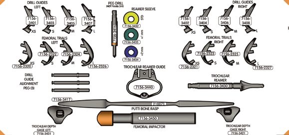
JOURNEY™ UNI and JOURNEY PFJ combination
preoperative planning and surgical technique

Table of contents
Preoperative planning............................................................................................2
Implant summary...................................................................................................9
Tibia cut first method summary.............................................................................11
Tibial preparation....................................................................................................12
Joint balancing.......................................................................................................17
Femoral preparation...............................................................................................19
Patellofemoral preparation.....................................................................................27
Resurfacing patellar preparation............................................................................39
Biconvex patellar preparation.................................................................................40
Final implantation...................................................................................................42
Instrument tray layout.............................................................................................45

Nota Bene
The technique description herein is made available to the healthcare professional to illustrate the
authors’ suggested treatment for the uncomplicated procedure. In the final analysis, the preferred
treatment is that which addresses the needs of the patient. Additional JOURNEY Active Knee
Solutions surgical technique brochures are available for the other JOURNEY Components.

1
Preoperative planning
 When addressing isolated OA disease of the medial or
 lateral condyle and the patellofemoral joint, consider
 using the JOURNEY™ Unicompartmental and JOURNEY
 Patellofemoral devices in combination. Radiographic
 preoperative planning is recommended in order to
 optimize implant sizing/positioning and to ensure that
 there is no impingement between the two implants or
 with any sourounding tissue or ligaments. Radiographic
 preoperative planning allows the surgeon to determine
 whether segmental devices or a total knee system would
 be the optimal treatment for each patient prior to surgery:

• Take standing, weight-bearing A/P and lateral radiographs
 of the knee, as well as a skyline radiograph of the patella.

• Optionally, the surgeon can request a non-weight bearing,
 valgus-stressed A/P radiograph, showing the leg in
 correct alignment. This view will help assess the amount
 of resection and implant construction necessary (if any) to
 correctly align the limb.

                                                                2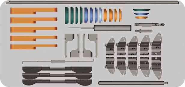
Preoperative planning continued
 Unicondylar implant sizing
 The size of the JOURNEY™ Unicompartmental femoral
 implant is estimated by comparing the lateral radiograph
 of the femur with the implant templates. The template size
 which most closely matches the profile of the femur on the
 distal and posterior aspects is chosen. Tibial templates                    Undersized
 are also available to approximate the size and thickness of
 components that will be needed for surgery.

 The images to the right illustrate the sizing criteria for three
 different UNI femoral implants on the same femur:
                                                                    JOURNEY UNI Size 3
• Size 3 is slightly undersized. It may be considered as
 functional, but not optimal

• Size 5 is oversized, with both posterior and anterior over hang

• Size 4 has an optimal fit to the articular surface, has good
 coverage and no over hang
 Part numbers for digital templates:
 JOURNEY UNI femoral:        7128-1472                                        Oversized
 JOURNEY UNI tibia:          7128-1783
 JOURNEY PFJ:                7128-1544

 Femoral component dimensions(mm)
  Size   AP     HT   ML    DM    PM
  1      40     31   19    5.5   5.5                                JOURNEY UNI Size 5
  2      43     32   20    5.5   5.5
  3      46     34   21    6.5   6.5
  4      49     36   22    6.5   6.5
  5      52     38   23    6.5   6.5
  6      55     40   24    6.5   6.5
  7      58     42   25    6.5   6.5

          10°                                                                Optimal

                                       PM
                                       PT
                                                                    JOURNEY UNI Size 4

                                                  HT
      M/L

 DM
 DT

                          AP
                          A/P

 3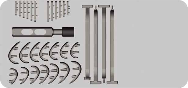
Unicondylar implant sizing/positioning
The size and M/L position of the JOURNEY™
Unicompartmental implant is estimated by comparing
                                                                Undersized
the A/P radiograph of the femur with the implant
templates. The template size that best fits the M/L
width of the femoral condyle should be chosen. Tibial
templates are also available to approximate the size
and thickness of components that will be needed
for surgery. In this example, size 4 provides the       JOURNEY UNI Size 3
optimal M/L fit.

                                                                 Oversized

                                                        JOURNEY UNI Size 5

                                                                  Optimal

                                                        JOURNEY UNI Size 4

                                                                             4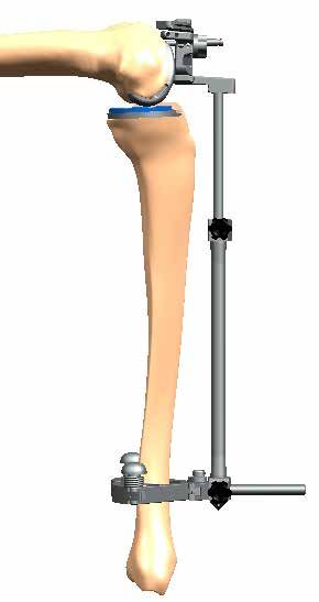
Preoperative planning continued
    Patellofemoral implant sizing/positioning
    Once the JOURNEY™ UNI femoral implant has been sized
    and positioned, next determine the size and position of the
    patellofemoral implant. The primary method for determining
    the appropriate size of the patellofemoral implant is assessing
    the M/L width of the implant relative to the M/L width of
    the femur. The best size will fully cover the anterior surface
    without overhang. Avoiding overhang is more important than
    complete coverage. Proximal-distal coverage is less critical.
    Leaving a small portion of cancellous bone uncovered should
    not compromise the result. Note: When positioning the
    patellofemoral X-Ray template, the surgeon should keep in
    mind that all sizes of the JOURNEY™ Patellofemoral implant are
    positioned centrally with respect to the trochlear groove.

    Note: Preoperative radiographic planning will assist the
    surgeon in determining size and placement. However, actual
    size may change once the anterior cortex of the femur has
    been resected in order to optimize implant coverage. When
    assessing the size and position of the JOURNEY Patellofemoral
    implant in combination with the JOURNEY Unicompartmental
    implant, both templates will need to be viewed simultaneously.
    This will allow the surgeon to determine preoperatively if the
    JOURNEY UNI femoral implant and the JOURNEY PFJ implant
    can be implanted without implant – implant or implant –
    ligament impingement.

•   Four femoral sizes with asymmetric components (left and right)

•   Uses GENESIS™ II round resurfacing or biconvex patella
    (do not use the JOURNEY Bi-Cruciate Stabilized patellar
    implants with the JOURNEY PFJ)

•   PFJ reimbursement code is 27438

•   Designing surgeons are John Newman, FRCS;
    William B. Smith, MD; Jeffrey R. Dugas, MD; and E. Lyle Cain, MD

    JOURNEY PFJ femoral component sizes
                        AP       ML        HT
        Extra Small     24       38        37
                                                                  A-P   M- L
        Small           24       42        37
        Medium          26       46        40
        Large           28       49        45
                                                                               H-

    5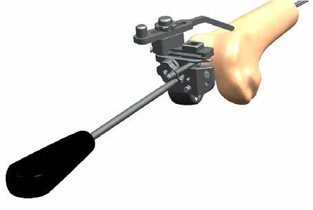
Unicondylar implant sizing/positioning

 JOURNEY™ PFJ Size SML          JOURNEY PFJ Size LRG         JOURNEY PFJ Size MED

 JOURNEY PFJ Size SML           JOURNEY PFJ Size LRG         JOURNEY PFJ Size MED
 Slightly undersized            Slightly oversized, slight   Optimal, complete coverage
                                lateral overhang             and no overhang

                                                                                          6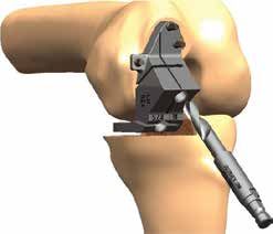
Preoperative planning continued
 Implant coordination
 Once the correct size and position of JOURNEY™ UNI
 and JOURNEY PFJ implants have been determined
 separately, assess how the implants will fit on the
 bone in combination by using the X-Ray. Specifically,
 assess the templates A/P positioning by using both
 implant templates simultaneously on the M/L film:

• Position the JOURNEY UNI femoral X-Ray template to the
 X-Ray of the femur.

• Keeping the JOURNEY Unicompartmental femoral
 template on the X-Ray, position the JOURNEY
 patellofemoral template on the X-Ray.

                                                           Lugs do
                                                           not impinge

                                                                  Cartilage, transition
                                                                  gap width

                                                           JOURNEY UNI Size 4
                                                           JOURNEY PFJ Size MED

 7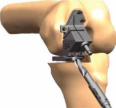
Once the correct position of unicompartmental and
 patellofemoral implant have been determined in the
 M/L film, assess position on the A/P view. Assess
 the M/L positioning by using both implant templates
 simultaneously on the A/P view:

• Position the JOURNEY™ UNI femoral X-Ray template to the
 X-Ray of the femur.

                                                            Cartilage, transition gap width

                                                            JOURNEY UNI Size 4
                                                            JOURNEY PFJ Size MED

 The devices can be implanted in combination to address     Cartilage, transition gap width

 bi-compartmental disease of the medial or lateral
 condyle and the patellofemoral joint if there is:
		– No implant – implant impingement
		– No implant – ligament impingement

                                                            JOURNEY UNI Size 4
                                                            JOURNEY PFJ Size MED

                                                                                              8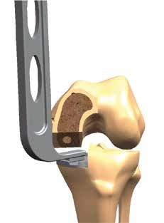
JOURNEY™ PFJ System
    For orthopaedic surgeons who prefer to use a partial
    knee implant system for the treatment of isolated
    patellofemoral disease, the JOURNEY PFJ offers the
    next generation of implant design, wear reduction, and
    market-leading ease of use and instrumentation.

    JOURNEY PFJ fast facts
•   Four femoral sizes with asymmetric components
    (left and right)

•   Uses GENESIS™ II round resurfacing or biconvex patella
    (do not use the JOURNEY Bi-Cruciate Stabilized patellar
    implants or oval patellas with the JOURNEY PFJ)

•   PFJ reimbursement code is 27438

•   Designing surgeons are John Newman, FRCS;
    William B Smith, MD; Jeffrey R. Dugas, MD; and
    E. Lyle Cain, MD

    JOURNEY PFJ femoral component sizes
                                                              A-P   M- L
                        AP       ML        HT
        Extra Small     24       38        37
        Small           24       42        37                              H- T
        Medium          26       46        40
        Large           28       49        45

    9
JOURNEY™ UNI Unicompartmental Knee System
Femoral component
• Asymmetric: The implant mimics the distal condyle’s
normal, anatomic shape by following a 10° A/P angle.
This allows the left medial component to be used
on the right lateral condyle, and the right medial
component to be used on the left lateral condyle.
• Anatomic: The implant comes in seven sizes in order
to customize the fit to the patient. The shape of the
sagittal J-curve is the result of extensive testing to
optimize function throughout the flexion arc. The
anatomic anterior mesial bevel is a design feature
that further optimizes the shape by ensuring smooth
patellar tracking in deep flexion.
• Bone interface: Three planar resections and two peg
holes provide a uniform, congruent cement interface.
The pegs significantly diverge from the posterior
planar resection, and the posterior peg is long enough
to aid in placing the component in small spaces for
final implantation. The entire mating surface, including
the pegs, is grit-blasted to enhance cement fixation.
• Versatility: Sizes 3, 4, 5, 6 and 7 all feature the exact
same planar resections and peg hole locations. Once
these preparations have been made, the 3 – 7 trials
are interchangeable, and can be up- and down-sized
until a decision is made for the final implant choice.
Sizes 1 and 2 are also interchangeable, with slightly
different cuts and peg locations than 3 – 7. Sizes
3 – 7 typically are used for 80% or more of uni cases.
Tibial component Anterior mesial lugs
• Asymmetric: The left medial component can be
used on the right lateral tibia, and the right medial
component can be used on the left lateral tibia.
• Flexibility: the implant comes in six sizes, and the poly
thickness increases in single millimeter increments
from 8 – 11mm to allow for fine-tuning the fit.* The
all-poly version and the metal-backed version have the
same instrumentation, allowing for easy intraoperative
choice. The all-poly version also has a thin 7mm
option. The same tibial system is used in JOURNEY
cases, so intraoperative options are increased.
• Unconstrained kinematics: when coupling a curved
femoral component on a flat articular surface,
unconstrained kinematics can be achieved. The
JOURNEY UNI system is an ACL/PCL conserving
device that lacks constraint, so the native ligaments
can control the movement of the knee.
*12 and 14mm options are available through InVentures.
10Tibia cut first method summary
Step 1 Step 6
Assemble the extramedullary Size the femur using the
tibial guide and place on 2-in-1 femoral cutting block.
tibia. Set tibial resection Position the 2-in-1 femoral
depth, posterior slope cutting block and pin it to
and sagittal alignment. the distal femur. Drill the peg
Pin the tibial cutting block. holes and resect the femur.
Step 2 Step 7
Resect the proximal tibia. Assemble the tibial hook
sizer and tibial sizer. Size
the tibia.
Step 8
Step 3 Assemble the femoral trial
Insert a gap stick into the on to the distal femur, insert
flexion/extension space the tibial base trial onto the
and balance the knee. proximal tibia and insert the
appropriate thickness of
tibial insert trials into the
tibial trial base. Perform a
trial range of motion.
Step 4 Step 9
Assemble the distal cutting Punch for tibial implant lugs.
block and appropriate tibial
trial insert. Align block with
drop rod assembly.
Step 10
Step 5 Cement the femoral and
Pin the distal cutting block tibial implants in place
to the femur. Resect the using the lugs to locate the
distal femur. position and orientation.
Using the tibial styli
• Some surgeons prefer to simply place an angel wing in the cutting slot in order to locate the
tibial transverse cut.
• If it is preferred to use a stylus in order to measure the resection, two double-ended styli are
offered to measure 2, 4, 6 or 8 millimeters of resection.
• Evaluate the degree of deformity during preoperative planning, as this will aid in determining
which stylus to use.
• If significant deformity is present, consider the 2-4 stylus in order to minimize the tibial resection.
• If deformity is minimal, consider the 6-8 stylus, because the thinnest metal backed tibia is 8
millimeters (total thickness, baseplate plus insert) and overstuffing the joint is to be avoided.
11Tibial preparation
Instrument assembly
1. Remove the long screw from the ankle clamp.
• Insert the ankle clamp into the hole of the EM
alignment tube and insert the long screw into
the ankle clamp. Lock the EM alignment tube to
the ankle clamp using the cam.
• Insert the selected rod, spiked or non-spiked,
into the hole of the tibial cutting block.
• Insert the rod into the proximal end of the EM
alignment tube, Lock the EM alignment Tube
to the rod using the cam.
• Place the extramedullary tibial ankle clamp
around the ankle and align the EM guide
parallel to the tibial axis in the sagittal and
coronal planes, then adjust in the sagittal plane
to account for the desired posterior tibial slope.
Note: The tibial cutting block has a neutral slope.
If posterior slope is desired, the extrameduallary
guide easily allows this.
Adjustable ankle clamp and Uni tibial Tibial alignment tube EM tibial spiked rod EM non-spiked rod
ankle clamp adjustment rod cutting block 7144-0448 7144-1338 7144-0446
7144-0444 7144-1335
12Tibial preparation continued
2. Option 1 – Spiked fixation rod
• Impact the posterior spike to secure the rod to
the tibial plateau.
• Rotate the extramedullary alignment guide
assembly to the medial one-third of the tibial
tubercle and adjust the ankle guide for desired
posterior slope.
• Impact the anterior spike of the spiked rod.
Option 2 – Non-spiked fixation rod
• Temporarily secure the tibial cutting block
to the non-spiked rod using the gold
thumb screw.
• Lock in place using the gold cam.
Note: The hex driver may be used to tighten
the gold thumb screw if desired.
3. Tibial resection depth
• Insert the paddle of the tibial stylus into the slot of
the tibial cutting block.
• There are two double sided tibial styli that allow for
resection depths of 2mm, 4mm, 6mm, and 8mm.
• Lower the tibial cutting block with the stylus
to the lowest point on the tibial plateau.
• Lock the tibial cutting block using the gold
thumb screw.
JOURNEY™ UNI mini JOURNEY UNI mini
tibial stylus 2 - 4mm tibial stylus 6 - 8mm
7401-3488 7401-3491
134. Sagittal resection alignment
• Care should be taken for proper rotation of the
cut. Tendency is to internally rotate the vertical
cut due to poor exposure next to the tendon
(often fat pad is in the way). A good rule of
thumb is the saw blade should be parallel to
the lateral wall of the medial femoral condyle.
• The tibial cutting block allows for further M/L
positioning after the depth has been set.
• To lock the M/L position once attained, use the
hex driver to lock the screw located in the
tibial cutting block.
Tip: A sagittal saw blade or resection check
placed through the vertical slot of the cutting
block will aid in the M/L position as well as
rotation alignment.
Note: The medial sagittal cut should be made
just medial to the insertion point of the ACL in
the tibial spine in order to maximize the size of
the tibial base.
5. Intersection pin
• Insert the quick connect drill or pin at the
intersection of the two tibial resection slots.
• Care should be taken to not damage the
posterior vascular structures by inserting the
drill or pin too far.
• Leave the drill or pin in place for resection.
Note: The drill or pin aids in the prevention of
over-resection.
Tip: If using the non-spiked fixation rod, the
oblique distal pin should be used for added
fixation if required.
Hex screwdriver Quick connect pin Quick connect 1/8” drill
7401-2441 7401-2904 7401-2905
14Tibial preparation continued
6. Tibial resections
Perform the sagittal and transverse resections.
Recommended oscillating blades*
Cat No. Description
7151-2905 Stryker 2000 1/2" straight
7151-2906 Old Stryker 2000 1/2” straight
7151-2907 Amsco Hall 1/2" straight
7151-2908 3M 1/2” straight
*Or any 0.053" or 1.35mm thick blade
Recommended reciprocating saw blades**
7144-1570 Stryker reciprocating saw blade
double-sided
7144-1573 Stryker reciprocating saw blade
single-sided
7144-1574 Amsco Hall reciprocating saw
blade single-sided
** .047" or 1.19mm for double-sided blades
.039" or 1.00mm for single-sided blades
Optimal tibial cut
As shown, the sagittal cut should be made
just medial to the ACL attachment point on the
tibial spine in order to maximize the size of the
tibial base.
Sub-optimal tibial cut
As shown, if the sagittal cut is made medial
to the tibial spine, it prevents maximization
of the size of the tibial implant which could
lead to lateralizing the femoral component
which may not be desirable. If this occurs, the
recommendation would be to redo the sagittal
cut just medial to the ACL attachment point on
the tibial spine in order to maximize the size of
the tibial base.
If the sagittal blade flexes, it can result in an
uneven cut along the tibial spine and will prevent
sizing the tibia accurately. If this occurs, redo the
sagittal cut using the saw or using the Bone Rasp
as shown in the next step.
157. Fine tuning tibial resections
• The bone rasp may be used to clean up the
resections, including the corner.
• The bone rasp has teeth along three faces of
the instrument.
• In the event that bone removal is necessary on
the sagittal resection but not the transverse,
the rasp may be turned upside-down as shown.
Bone rasp
7144-1351
16Joint balancing
8. Checking gap balance
• Place the appropriate gap stick into the
flexion/extension space between the femur
and resected tibia to balance the joint.
• The thickness of gap stick that balances the
joint in flexion and extension will determine
the thickness of tibial insert poly to be used in
conjunction with the distal cutting block as well
as implant trialing and implantation.
• Typically when extension is balanced, flexion
will be tight due to distal condyle disease.
Note: Gap stick thicknesses are: 7mm,
8mm, 9mm, 10mm and 11mm. These are the
thicknesses currently offered in the
JOURNEY™ UNI tibial inserts. The 7mm option is
only available in the all poly option, not the metal
backed tibia.
Tip: Many surgeons advise to check the
extension gap in 10° – 20° of flexion to account
for the screw-home mechanism.
Fine tuning
• The bone rasp can be used to fine-tune the
gap balancing by removing 1 or 2mm of
cartilage off of either the posterior or distal
condyle as appropriate (see gap balancing
chart on the next page).
• The joint should be balanced in flexion
and extension.
Tip: Many surgeons consider a 2mm flexion and
extension gap when valgus stress is applied to
a medial uni to be a good rule of thumb. Some
accept a slightly larger gap in flexion when using
a fixed bearing tibia. The tibial insert handle is
1.5mm and can be used to help assess laxity.
JOURNEY™ UNI gap stick Bone rasp Tibial insert handle
7401-3474 7144-1351 7123-6012
179. Gap balancing, after tibial cut
Scenario Flexion Gap Extension Gap Next step
1 Good Good Remove equal thickness distal and posterior femoral bone. The distal and 2-in-1
cutting blocks are designed to do this. Rule of thumb is a 2mm gap upon valgus
stress in a medial uni.
2 Good Tight Use bone rasp to remove 1mm to 2mm of cartilage from the distal condyle prior
to femoral resections, or recut the tibia with less or no slope and accept modest
flexion laxity since the cruciate ligaments are intact.
3 Good Loose Consider removing less distal femoral bone with the 4.5mm distal block in order
to build up the extension gap but not the flexion gap.
4 Tight Good Use bone rasp to remove 1mm to 2mm of cartilage from the posterior condyle prior
to femoral resections.
5 Tight Tight Remove more proximal tibia, assess if scenario one can be achieved with the
gap sticks.
6 Tight Loose Can be challenging. Often in ACL deficient knees/lateral unis where the wear
pattern is more posterior than distal. In the chronic ACL deficient knee, PCL
contracture can occur, resulting in excessive rollback. The wear pattern can
effectively create more slope, and it is common to under-resect, leading to relative
overstuffing of the posterior space. In these cases you tend to get more fixed
medial contracture (vs. correctable) but still have some anteromedial cartilage so
the joint is tighter in flexion. Solutions include resecting less distal femur with the
4.5mm block, rasping 1 – 2mm of cartliage from the posterior condyle in order to
shift the femoral component anteriorly, and increasing the tibial slope.
7 Loose Good Carefully examine the degree of laxity in flexion. Many uni surgeons agree that
with fixed bearing tibias, modest laxity in flexion (slightly greater than the 2mm
rule of thumb) can be acceptable. The cruciate ligaments are retained, and more
normal kinematics are still achieved. If flexion is deemed unacceptably loose, one
option is to remove less posterior bone by allowing a space between the posterior
paddle of the 2-in-1 cutting block before pinning so that less than 6.5mm of
posterior bone is removed. Another is to remove more distal bone and increase
the thickness of tibial poly.
8 Loose Tight Extremely rare. UKA might not be indicated. Options are similar to scenario 7 but
harder to address.
9 Loose Loose Trial with the next mm increment of gap stick, assess if scenario one can be
achieved with thicker poly. The poly increases in small, 1 mm increments, so
balancing can be fine-tuned.
Optional
The drop rod can be used with the gap sticks to
check A/P slope and varus/valgus of the tibial
resection and overall limb alignment.
Extramedullary alignment rod JOURNEY™ UNI gap stick
114861 7401-3474
18Femoral preparation
10. Instrument assembly
Choose the appropriate size and hand distal
cutting block required to make the distal
resection (the options are 4.5mm and 6.5mm).
Note: The 4.5 mm distal resection block should
only be used in situations where you are trying
to build up the extension gap, but not the flexion
gap, by taking less distal femoral bone. This
situation arises after the tibial cut and before the
femoral cut, where the extension gap is loose and
the flexion gap is not. See the previous page for a
more detailed explanation in scenario 3 and 6.
Locate the tibial trial insert that will allow
maximum coverage of the resected tibial
plateau and is the identical thickness of the gap
stick used to balance the joint in flexion and
extension (eg, 8mm gap stick = 8mm trial insert).
Invert the tibial trial insert so that the groove is
facing upward.
Insert the tibial trial insert onto the lower rail
of the distal cutting block.
• Insert the drop rod assembly into the distal block.
•Assemble the drop rod by screwing the two
ends together while capturing the flange of the
drop rod slot closest to the midline of the knee.
or
• Assemble the drop rod by screwing the two
ends together and insert into the drop rod Assessing alignment After alignment
hole closest to the midline of the knee.
11. Extramedullary alignment
• Insert the distal block and tibial insert trial
assembly into the extension space.
• Assess the M/L placement of the distal block in
order to avoid pinning into the trochlear groove.
• Use the drop rod assembly to ensure the distal
resection is made perpendicular to the femoral
axis. To accomplish this, it may be necessary to
slightly flex the knee to compensate for posterior
tibial slope.
Note: A vertical line has been marked onto the
top and anterior faces of the block to help assess
block alignment prior to pinning.
JOURNEY™ UNI distal block JOURNEY UNI tibial trial insert 65mm Rimless speed pin JOURNEY UNI Extramedullary alignment rod
7401-3442 7143-6133 7500-9338 Drop rod assembly 114861
7401-3496
1912. Distal resection
• Use the drop rod assembly to ensure the
distal resection is made perpendicular to the
femur. To accomplish this, it may be necessary
to slightly flex the knee to compensate for
posterior tibial slope.
• Assess block position.
• Pin the Distal Block to the femur.
• Resect the distal femur.
JOURNEY™ UNI distal block JOURNEY UNI tibial trial 65mm Rimless speed pin
7401-3442 7143-6133 7500-9338
20Femoral preparation continued
13. Checking gap balance:
Insert the thick end of the same gap stick previously
used to balance the joint in extension bullet point:
The thick end of the gap stick represents the total
thickness of the selected poly insert, tibial baseplate
and distal femoral condyle implant.
Note: Femoral implant sizes 1 and 2 are 1mm thinner
in the posterior and distal condylar thickness
dimensions than sizes 3-7 (sizes 1 and 2 are 5.5mm
and sizes 3-7 are 6.5mm). When trialing with a size
1 or 2 femur, it is possible for gap balancing with the
gap stick to be perfect after the tibial and femoral
cuts, and then have 1mm of laxity in flexion and
extension. If the patient is very small and has the
potential for a size 1 or 2, ensure that your initial tibial
cut does not require the largest insert thickness of
11mm.
14. Femoral block sizing, positioning and fixation
• The size of block is determined by optimizing
the coverage of the distal resection without
overhang and positioning to the posterior condyle.
• The anterior edge of the block should not go
beyond the anterior edge of the distal resection
but should be 1mm to 1.5mm posterior of the edge.
• The M/L position of the 2-in-1 femoral block is
obtained by locating it to give optimal coverage
of the distal resection and positioning to the
posterior condyle.
Note: To assist in component positioning, the blocks
have the same footprint as the implants.
Tip: The A/P cuts and peg hole location are the same
for sizes 3, 4, 5, 6, and 7. Once cuts are made and
peg holes drilled, up- or down-sizing is still available.
Tip: The A/P cuts and peg hole location are the same
for sizes 1 and 2. Once cuts are made and peg holes
drilled, up- or down-sizing is still available between
these two sizes. If between sizes 2 and 3; size 2
should be selected.
Note: There is a laser-etched line down the middle of
the block to assist with M/L positioning.
Tip: Use the JOURNEY™ UNI 2-in-1 block QC handle to
assist in cutting block positioning.
JOURNEY UNI gap stick JOURNEY UNI 2-in-1 JOURNEY UNI 2-in-1
7401-3474 Femoral block block QC handle
7401-3454 7401-3486
2115. Anterior pin and toggle
• Ensure that the 2-in-1 block is flush to the distal
resection and posterior condyle once the
optimal position has been achieved.
• Insert a headed pin into anterior pin hole.
• Finalize rotation of the block.
16. Second and third pin
• Insert the medial outboard pin.
• Insert the lateral distal pin. – optional
Tip: Adequate fixation can be possible without
inserting the medial outboard pin when the
Alignment peg is used.
Note: When positioning the 2-in-1 block, keep
in mind that the footprint is the same as the
corresponding implant.
Note: You do not want the block or the implant
to overhang off the most anterior part of the
distal cut.
Note: If there is 1 – 2mm of uncovered anterior
bone between the anterior edge of the
implant and the perimeter of the resection,
this is acceptable.
JOURNEY™ UNI 2-in-1 JOURNEY UNI 2-in-1 45mm Rimmed speed pin
femoral block block QC handle 7501-8973
7401-3454 7401-3486
22Femoral preparation continued
17. Femoral peg hole preparation
• Drill the anterior peg hole.
• Insert the alignment peg into the prepared
anterior peg hole.
• Drill the posterior peg hole.
JOURNEY™ UNI 2-in-1 JOURNEY UNI 2-in-1 45mm Rimmed speed pin JOURNEY UNI JOURNEY UNI femoral
femoral block block QC handle 7501-8973 femoral lug drill alignment peg
7401-3454 7401-3486 7401-3485 7401-3487
2318. Resect the posterior condyle.
Note: The posterior cut is a flexed cut at 105°
from the distal cut, allowing for optimal bone
coverage in flexion while maintaining the
6.5mm thickness.
• Remove the alignment peg and resect the
posterior chamfer.
Note: The posterior paddle serves as a
blade stop when the posterior chamfer cut
is being made.
• Remove pins and block.
JOURNEY™ UNI 2-in-1 JOURNEY UNI 2-in-1 45mm Rimmed speed pin JOURNEY UNI JOURNEY UNI femoral
femoral block block QC handle 7501-8973 femoral lug drill alignment peg
7401-3454 7401-3486 7401-3485 7401-3487
24Femoral preparation continued
Instrument assembly
• Insert the JOURNEY™ UNI tibial hook sizer into
the appropriate JOURNEY UNI tibial sizer.
19. Sizing the tibia
• Insert the tibial sizer assembly into the joint.
• Pull the assembly anteriorly until the posterior
hook engages the posterior cortex.
• The tibial sizer should completely cover the
resected tibial plateau without overhang.
Note: The hook sizer can be used to size the
tibia without the tibial sizer
JOURNEY UNI tibial sizer JOURNEY UNI
7401-3482 tibial hook sizer
7401-3484
2520. Trial reduction and final preparation
• Insert the tibial base trial onto the proximal tibia.
• Assemble the appropriate size femoral trial onto
the distal femur.
• Insert the appropriate thickness and size of the
tibial insert trial into the tibial baseplate trial.
• Perform a trial range of motion.
• Check to make sure the femur sits in the middle
of the tibia both in flexion and extension.
This is to prevent edge loading. The laser etched
line on the block in step 14 will likely ensure
centering of the component. This is a final check.
Tip: The tibial base trials have small spikes to
prevent movement during trialing.
Note: Femoral sizes 3 - 7 share same cuts and
peg locations so size adjustments can be made
if needed.
Remove femoral trial
• Punch for the tibial pegs using the tibial punch
in the appropriate size.
Note: Before cementing the final implants, prepare
the patella femoral joint with the JOURNEY™ UNI
trials in place.
JOURNEY UNI fixed JOURNEY UNI JOURNEY UNI Tibial punch Tibial insert handle
bearing femoral trial tibial base trial tibial trial insert 7144-1347 7123-6012
7401-3424 7143-6124 7143-6133
26Patellofemoral preparation
Preoperative note: If replacing the patella, use
GENESIS™ II biconvex or round resurfacing implant.
Do not use the JOURNEY™ BCS Total Knee Patellar
Component.
21. Maneuver patella out of the joint space without
everting. Place the Offset EM Alignment Rod on the
anterior femur. The rod goes underneath the quad,
on top of the femur, and serves as a guide to ensure
that the intramedullary rod is inserted parallel, not
breaching the femoral cortex.
At this point, you can free-hand a parallel opening
in the canal, or use the “L” shaped drill guide in step
3. The opening needs to be high in the canal, not
centered.
Drill IM canal pilot hole
22. Using the EM Alignment Rod for visual alignment of
flexion, open the femoral canal with the 4.75mm drill.
The “L” shaped IM drill guide (shown at right) can be
used as an aid in placement and ensuring creation of
an opening that is parallel to the canal.
This drill bit connects
to a mini-connector
Insert IM rod
23. Attach the 4.7mm IM Rod to the T-Handle inserter.
Place the 4.7mm IM Rod into the opening hole until it
stops at the depth stop. Double-check A-P alignment
with EM Alignment Rod.
27Patellofemoral preparation continued
24. Connect cutting guide to IM rod
Slide the Anterior Cutting Guide onto IM Rod from the
medial side until a “click” is heard.
Tip: Some surgeons, even with a medial incision on
a left knee, have preferred the right anterior cutting
guide. This is perfectly acceptable; the same anterior
cut can be achieved with either guide.
Cutting guide rotational alignment
Method 1: Tibial referencing
25. Draw the AP Axis along the trochlear groove using
a cautery or a marking pen. There are both femoral
and tibial referencing methods. Tibial referencing is
considered the primary method, with the femoral
referencing as a secondary check.
25a. Attach the tibiofemoral alignment ankle clamp to the
ankle, and align the vertical rod with the tibial shaft.
Flex the knee to 90°.
Clinical studies support determining the femoral
component rotation by referencing a line
perpendicular to the longitudinal tibial shaft axis.
28Cutting guide rotational alignment
25b. Align the platform on the top of the alignment guide
with the bottom face of the Anterior Cutting Guide.
The platform should be flush or nearly flush with
the bottom of the anterior cutting guide. In proper
alignment, there is typically less than 1° or 2° of
difference between the femoral and tibial referencing.
25c. When pinning the guide, a pin driver may be desired.
Select two or three of the five holes for optimal
fixation. One of the holes chosen needs to be the
outrigger pinhole. Please see Step Eight for more
detail on pinning the Anterior Cutting Guide.
25d. A shorter pin is included in the set for the
medial outrigger.
29Patellofemoral preparation continued
Cutting guide rotational alignment
Method 2: A/P Axis/Epicondylar Axis Visualization
25e. Attach the Quick Connect Handle to the pocket on top
of the Anterior Cutting Guide by depressing the gold
button on the handle.
25f. Slide the long axis of the Alignment T-Bar through one
of the holes in the quick connect handle all the way
until it snaps on around the quick connect handle.
Visualize anterior cut
25g. Using the T-Bar as a visual guide, align the Anterior
Cutting Guide in 0°-3° of external rotation. A second
quick connect handle can be attached to the medial
part of the cutting guide to stabilize while pinning.
QC Handle pocket
30Visualize anterior cut
25h. If you are satisfied with the alignment at this point,
you can choose to go ahead and pin the guide.
Pinning guidelines are in step 8. Tibial referencing
is a secondary check, detailed on the next page.
26. Pin the Anterior Cutting Guide using the headed
pins provided in the set. It is helpful to pre-drill the
pin holes to prevent twisting of the guide when
impacting the pins into place. Two to three pins,
one of which is inserted in the medial outrigger
pinhole, are sufficient to assure stability.
31Patellofemoral preparation continued
27. Set depth and resect anterior femur
Place the Anterior Cutting Guide with the sizing stylus
referenced off of the low point of the center of the
trochlea on the anterior aspect of the femur. Turn knob
to adjust height. Height may also be checked with the
Resection Check (angel wing) in the cutting slot. When
proper height is reached, use the hex driver to tighten
the set screw and lock the cutting guide in place.
Resect the anterior femur.
Note: the adjustable nature of this guide allows you
to undercut and then shave down sequentially to
make every resection ideal.
28. Position drill guide
• Size the femur by placing the appropriate drill guide
onto the femur and judging the fit. If desired, a Quick
Connect handle can be placed in the drill guide.
• Using a cautery, mark the location of the laser mark
on the top of the drill guide.
• Drill preparation holes for the reamer guide through
the proximal two holes marked with bull’s-eyes and
pin in place with headless pins.
• Mark the intercondylar region with a cautery or
marking pen.
• Remove the Drill Guide by sliding over the pins.
Leave the pins in place
Mark intercondylar edges
with cautery or marker
3229. Secure reamer guide
• Place the reamer guide onto the cut surface, sliding
the guide over the pins into the slots in the
reamer guide until the tip of the guide touches the
intercondylar region and can not slide any further.
• Removing a small amount of bone or cartilage from
the notch can sometimes help to fully seat the
reamer guide.
• Align the laser line on the center of the anterior
surface with the appropriate (L or R) cautery mark
made in Step Ten.
• Assure that the reamer guide sits flush against the
anterior cut surface.
• Pin one additional headed short pin in one of the
open holes to secure the device.
• Place one pin into the trochlear region through
the distal portion of the resection guide. There
are three holes to choose from, but only one hole
can be selected.
Align cautery mark with
the appropriate laser
mark on the guide.
Short-headed pin
(under the pin
driver in this image)
• Placement of the reamer guide will decide how assures stability
much or little trochlea bone is removed.
• Keeping the tip out of the notch will prevent going
too deep with the first reamer and will allow the
deeper reamers to be used in the event more
depth is needed.
Choice of three holes, but only
one can be used at a time. Do not
pin under the unicondylar trial.
33Patellofemoral preparation continued
30. Choose reamer depth
Attach the Yellow Reamer Sleeve to the reamer shaft
as shown. Attach the reamer to the drill. In most cases,
the yellow sleeve will be all that is required to achieve
adequate depth. Use your depth gauges often to avoid
over reaming. Over reaming may make the patella jump
as it changes from one surface to the other. The darker
the sleeve, the deeper you ream.
Order of reamer sleeves:
Yellow = standard
Green = +1mm
Blue = +2mm
Darker is deeper.
31. Ream trochlear bone
Place the round reamer tip into the round depression
in the reamer guide and ream the trochlear region from
medial to lateral and back. Using a small amount of
force to keep the reamer in contact with bone, ream
up to but not touching the cautery/marker lines that
denote the outer boundary of the implant that were
made in step 10.
Tip: Instead of immediately going back and forth
across the reamer guide, some surgeons prefer to
bring the reamer directly towards the guide in a straight
line until the sleeve reaches the guide, and then begin
the side to side motion. This technique can facilitate
reaming and let the surgeon focus on resurfacing just
to the tide marks.
34Patellofemoral preparation continued
Note: You only have to ream to the mark, not
to the sides of the guide.
Reaming is complete once the sleeve maintains
contact with the guide throughout the range of
motion to the edges of the intended implantation
site. In many cases, you will only need the first
sleeve to achieve the necessary depth for a
smooth transition zone.
32. Assess reamed depth
When the yellow reamer sleeve will not allow any
further reaming depth, remove the reamer from the
guide and place the Trochlear Depth Gauge into the
reamed region to judge the reaming depth. If more
bone removal is necessary, the Green +1mm sleeve
or Blue +2mm sleeve may be used to increase the
depth and width of the reamed area. In most cases,
the yellow sleeve will be sufficient. Check reaming
depth each time with the Trochlear Depth Gauge
before switching to a more aggressive reamer sleeve.
3533. When reaming is complete, place the drill guide onto
the femur. If necessary, the Putti Rasp may be used to
fine tune the component fit.
33a. If desired, pins can be inserted through the laser
etched smaller holes to stabilize the guide. If it is
preferred to avoid these pins, alignment pegs may
be used. These are exactly the same depth as
the implant pegs, so no unnecessary pinholes are
created.
33b. Use the Peg Drill to drill the first peg hole in the top of
the implant. The suggested order is top, bottom, then
both sides.
33c. Once drilled, insert an Alignment Peg in the hole to
stabilize the guide.
36Patellofemoral preparation continued
Drill peg holes
33d. Repeat the drill and fill process in the bottom hole.
Drill the bottom hole with the Peg Drill.
33e. Insert another Alignment Peg, leaving the top
Alignment Peg in place as well.
Drill
peg holes
33f. Drill the third hole.
33g. Drill the fourth hole.
3734. Patellofemoral trialing
• Place femoral trial. Begin by inserting the distal/
posterior hole and lever the trial into place, using light
taps on the impactor to seat the component.
– In most cases, the bone will be soft enough to lever
the trial in place. With hard or eburnated bone, it
may be necessary to open up the inferior portion of
the top three holes with a drill in order to seat the
component.
– This design fits tightly. Take care when removing the
trial. Start by lifting the proximal end.
• Prepare patella with same technique and instruments
as a standard GENESIS™ II Total Knee Replacement.
– Do not use the JOURNEY™ BCS Total Knee
Patellar Component.
38Resurfacing patellar preparation
The surgeon can choose from a free hand cutting
technique with towel clips or if desired he or she can
choose one of the following instrumented techniques.
34a. Method 1: Resection guide technique
• Measure the overall thickness of the patella with the
patellar calipers.
• Subtract from this number the thickness of the
GENESIS™ II round resurfacing patellar component – 9mm.
• The guide is set at the amount of bone that needs
to remain after cutting the patella – ie the difference
between the original patellar thickness and 9mm. The
guide is set at this level by turning the knurled knob.
• Cut the patella through the full dedicated saw guides.
• Drill for the three pegs, insert the resurfacing patellar
trial and remeasure.
– The overall thickness should be equivalent to the
original thickness.
Note: The reaming technique described for the
biconvex patella can be used as well. The only
differences in technique are to use the red
resurfacing depth gauge, resurfacing reamers
and the resurfacing drill guides.
39Biconvex patellar preparation
34b. Method 2: Insert Technique
Instrument assembly: Determine the appropriate
diameter patellar implant and select the correctly
sized patellar reamer collet and slide it into place on
the patellar reamer guide.
• Attach the patellar reamer guide to the patella.
Tighten the patellar reamer guide on the patella.
• Use the patellar calipers to measure the thickness
of the patella.
40Biconvex patellar preparation continued Instrument assembly: Attach the blue Patellar Depth Gauge to the Reamer Guide. Attach the matching sized Patellar Reamer Dome and Patellar Depth Stop to the Patellar Reamer Shaft. Lower the assembly through the Patellar Reamer Guide until the Reamer Dome contacts the patella. • Swing the Patellar Depth Gauge around so that the “claw” surrounds the Patellar Reamer Shaft. • Lower the Patellar Depth Stop by pushing the gold button until it contacts the Patellar Depth Gauge. The Patellar Depth Stop will automatically lock in place (bottom image). • Remove the depth gauge. • Ream the patella until the depth stop engages the patellar reamer guide. Often in these cases, the patella will be very thin (10-18mm). In those cases, stop well short of the measured resection and remove minimal patellar bone. A shallow rim is all that is required for the inset and you may save 6-8mm of patella for the future. • Place the patella trial button onto the prepared patella. • Perform a trial range of motion with the trial components in place. 41
Final implantation steps
35. Final   UNI implantation
 • Thoroughly clean the femur and tibia.

 • Ensure implants are completely dry.

 • Cement the femoral and tibial implants in place using
   the pegs to locate the position and orientation.
 • To pressurize the cement, a Tibial Insert Trial of the
   appropriate size may be placed in the Tibial Base
   Implant during this time. Note: Care should be taken
   to avoid excess cement on the posterior aspect of
   the femur and femoral component. Excess cement
   that extrudes posteriorly is difficult to remove.

                                                            42
Final implantation continued
36. Insertion of the articular insert
• Thoroughly clean the Tibial Base Implant
making sure that no debris is present
in the locking area or on the mesial rail.
• Ensure there is no protrusion of the vertical
wall of the tibia impeding the insert from
aligning properly (utilize rasp on vertical
wall if required)
• Slide the tibial insert at a shallow angle
along the A/P spine posterior ensuring the insert
doesn’t impinge on the vertical tibial eminence
until the insert will not go further.
• Once insert is positioned and aligned as
far posteriorly as possible apply a posteriorly
directed and distal force with thumb/finger
pressure until the anterior lock portion of
the insert engages the tibial base.
• If necessary, the tibial impactor may be
used to seat the insert with the aid of a
mallet using a gentle tap.
• If the insert does not immediately lock with finger
pressure, ensure the insert is properly aligned in
the baseplate by pushing the
insert from the outside toward the tibial
spine with finger pressure.
This gap is normal
and allows for the
insertion of an
extraction tool, if
required.
Tibial impactor
7123-6968
4337. Final PFJ implantation
• Ensure implants are completely dry.
• Cement the patellofemoral implant in place using
the pegs to locate the position and orientation.
• Begin by inserting the distal/posterior hole and
lever the implant into place, using light taps on the
impactor to seat the component.
• Assemble the Patellar Cement Clamp to the Patellar
Reamer Guide.
• Apply bone cement to the reamed patella.
• Place the patellar implant onto the prepared patella.
• Clamp the patellar implant into the bone and
remove the extruded cement.
38. Completion
• Irrigate the components thoroughly, perform
routine closure and wound management.
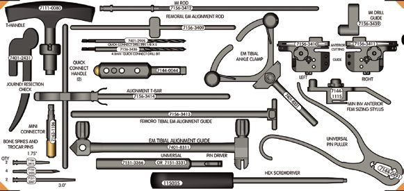
44Tray layouts
7142-2378 - JOURNEY™ UNI tray 1
A B C
D
F
E
H
N
O
P
I K L
M
J Q
Ref. letter Cat. no. Description
A 7401-3488 JOURNEY UNI mini tibial stylus 2mm and 4mm
B 7401-3491 JOURNEY UNI tibial stylus 6mm and 8mm
C 7144-0446 GENESIS™ II non-spike fixation rod
D 7144-0448 GENESIS II tibial alignment tube
E 7144-1338 JOURNEY EM tibial spiked rod
F 7144-0380 GENESIS II resection check
H 7144-0444 GENESIS II adjustable ankle clamp & alignment rod
I 7144-1335 JOURNEY UNI tibial cutting block Left
J 7144-1336 JOURNEY UNI tibial cutting block Right
K 7144-0491 Universal pin puller
L 7163-1186 Mini connector
M 7401-3489 Speed pin quick connect
N 7401-2441 JOURNEY 3.5 mm hex driver
O 7144-1351 JOURNEY bone rasp
P 7151-3331 Universal pin driver
Q 7401-2451 JOURNEY slap hammer extractor
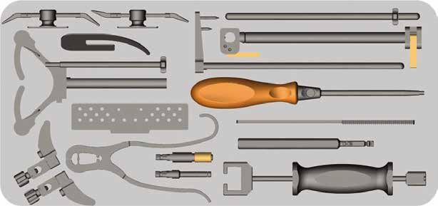
457142-2379 JOURNEY™ UNI tray 2
A
L N P R T V X
B
Y
M O Q S U W Z
C
AB
AA
D AC
AD AG
E
AH AI AJ AK AL
F
AE AF
G Drop Rod Assembly
H
I
AM AN AO AP AQ
J
K AR
Ref. letter Cat. no. Description Ref. letter Cat. no. Description
A 114861 Extramedullary alignment rod JOURNEY UNI all poly tibial trial insert
B 7401-3477 JOURNEY UNI gap stick 11mm / 17.5mm X 7143-6144 Sz 5-6 7mm
C 7401-3476 JOURNEY UNI gap stick 10mm / 16.5mm JOURNEY UNI all poly tibial trial insert
Y 7143-6143 Sz 3-4 7mm
D 7401-3475 JOURNEY UNI gap stick 9mm / 15.5mm
JOURNEY UNI all poly tibial trial insert
E 7401-3474 JOURNEY UNI gap stick 8mm / 14.5mm Z 7143-6142 Sz 1-2 7mm
F 7401-3473 JOURNEY UNI gap stick 7mm / 13.5mm AA 7123-6012 ACCURIS™ Tibial insert handle
G 7401-3496 JOURNEY UNI drop rod assembly AB 7401-3485 JOURNEY UNI femoral lug drill
H 7401-3484 JOURNEY UNI tibial hook sizer AC 7401-3487 JOURNEY UNI femoral alignment peg
I 7401-3481 JOURNEY UNI tibial sizer Sz 1-2 AD 7401-3441 JOURNEY UNI distal block LM 4.5mm
J 7401-3482 JOURNEY UNI tibial sizer Sz 3-4 AE 7401-3442 JOURNEY UNI distal block LM 6.5mm
K 7401-3483 JOURNEY UNI tibial sizer Sz 5-6 AF 7401-3444 JOURNEY UNI distal block RM 6.5mm
L 7143-6141 JOURNEY UNI tibial trial insert Sz 5-6 11mm AG 7401-3443 JOURNEY UNI distal block RM 4.5mm
M 7143-6139 JOURNEY UNI tibial trial insert Sz 5-6 10mm AH 7401-3458 JOURNEY UNI 2-in-1 fem block LM Sz 1-2
N 7143-6138 JOURNEY UNI tibial trial insert Sz 5-6 9mm AI 7401-3453 JOURNEY UNI 2-in-1 fem block LM Sz 3
O 7143-6137 JOURNEY UNI tibial trial insert Sz 5-6 8mm AJ 7401-3454 JOURNEY UNI 2-in-1 fem block LM Sz 4
P 7143-6136 JOURNEY UNI tibial trial insert Sz 3-4 11mm AK 7401-3455 JOURNEY UNI 2-in-1 fem block LM Sz 5
Q 7143-6135 JOURNEY UNI tibial trial insert Sz 3-4 10mm AL 7401-3459 JOURNEY UNI 2-in-1 fem block LM Sz 6-7
R 7143-6134 JOURNEY UNI tibial trial insert Sz 3-4 9mm AM 7401-3468 JOURNEY UNI 2-in-1 fem block RM Sz 1-2
S 7143-6133 JOURNEY UNI tibial trial insert Sz 3-4 8mm AN 7401-3463 JOURNEY UNI 2-in-1 fem block RM Sz 3
T 7143-6132 JOURNEY UNI tibial trial insert Sz 1-2 11mm AO 7401-3464 JOURNEY UNI 2-in-1 fem block RM Sz 4
U 7143-6131 JOURNEY UNI tibial trial insert Sz 1-2 10mm AP 7401-3465 JOURNEY UNI 2-in-1 fem block RM Sz 5
V 7143-6129 JOURNEY UNI tibial trial insert Sz 1-2 9mm AQ 7401-3469 JOURNEY UNI 2-in-1 fem block RM Sz 6-7
W 7143-6128 JOURNEY UNI tibial trial insert Sz 1-2 8mm AR 7401-3486 JOURNEY UNI 2-in-1 block QC handle
46Tray layouts continued
7142-2381 JOURNEY™ UNI tray 3
A C E G I K
B D F H J L
AB AC AD AE
M
This space reserved for
N O P Q R S T joint line referencing instuments.
U V W X Y Z AA
Ref. letter Cat. no. Description Ref. letter Cat. no. Description
A 7143-6121 JOURNEY UNI tibial base trial Sz 1 LM/RL U 7401-3431 JOURNEY UNI fixed bearing fem trial RM Sz 1
B 7143-6122 JOURNEY UNI tibial base trial Sz 2 LM/RL V 7401-3432 JOURNEY UNI fixed bearing fem trial RM Sz 2
C 7143-6123 JOURNEY UNI tibial base trial Sz 3 LM/RL W 7401-3433 JOURNEY UNI fixed bearing fem trial RM Sz 3
D 7143-6124 JOURNEY UNI tibial base trial Sz 4 LM/RL X 7401-3434 JOURNEY UNI fixed bearing fem trial RM Sz 4
E 7143-6125 JOURNEY UNI tibial base trial Sz 5 LM/RL Y 7401-3435 JOURNEY UNI fixed bearing fem trial RM Sz 5
F 7143-6126 JOURNEY UNI tibial base trial Sz 6 LM/RL Z 7401-3436 JOURNEY UNI fixed bearing fem trial RM Sz 6
G 7143-6156 JOURNEY UNI tibial base trial Sz 6 RM/LL AA 7401-3437 JOURNEY UNI fixed bearing fem trial RM Sz 7
H 7143-6155 JOURNEY UNI tibial base trial Sz 5 RM/LL AB 7144-1353 JOURNEY UNI tibial impactor
I 7143-6154 JOURNEY UNI tibial base trial Sz 4 RM/LL AC 7144-1346 JOURNEY UNI tibial punch Sz 1-2
J 7143-6153 JOURNEY UNI tibial base trial Sz 3 RM/LL AD 7144-1347 JOURNEY UNI tibial punch Sz 3-4
K 7143-6152 JOURNEY UNI tibial base trial Sz 2 RM/LL AE 7144-1348 JOURNEY UNI tibial punch Sz 5-6
L 7143-6151 JOURNEY UNI tibial base trial Sz 1 RM/LL
M 7123-6952 ACCURIS™ femoral impactor
N 7401-3427 JOURNEY UNI fixed bearing fem trial LM Sz 7
O 7401-3426 JOURNEY UNI fixed bearing fem trial LM Sz 6
P 7401-3425 JOURNEY UNI fixed bearing fem trial LM Sz 5
Q 7401-3424 JOURNEY UNI fixed bearing fem trial LM Sz 4
R 7401-3423 JOURNEY UNI fixed bearing fem trial LM Sz 3
S 7401-3422 JOURNEY UNI fixed bearing fem trial LM Sz 2
T 7401-3421 JOURNEY UNI fixed bearing fem trial LM Sz 1
47JOURNEY™ PFJ instrument tray
48Notes 49
Notes

        50
Smith & Nephew, Inc. www.smith-nephew.com 7135 Goodlett Farms Parkway Cordova, TN 38016 USA Telephone: 1-901-396-2121 Information: 1-800-821-5700 Orders and Inquiries: 1-800-238-7538 ™ Trademark of Smith & Nephew. Reg. US Pat. & TM Off. All Trademarks acknowledged. ©2013 Smith & Nephew, Inc. All rights reserved. The color Pantone 151 Orange for medical instruments is a U.S. registered trademark of Smith & Nephew. 00295 V1 11/13
You can also read