Oxford Partial Knee Microplasty Instrumentation - Surgical Technique
←
→
Page content transcription
If your browser does not render page correctly, please read the page content below
Oxford Partial Knee
         ®

Microplasty ® Instrumentation

     Surgical Technique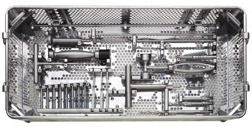
One Surgeon. One Patient.
                        ®   Over 1 million times per year, Biomet helps one surgeon
                            provide personalized care to one patient.

                            The science and art of medical care is to provide the right
                            solution for each individual patient. This requires clinical
                            mastery, a human connection between the surgeon and the
                            patient, and the right tools for each situation.

                            At Biomet, we strive to view our work through the eyes of
                            one surgeon and one patient. We treat every solution we
                            provide as if it’s meant for a family member.

                            Our approach to innovation creates real solutions that assist
                            each surgeon in the delivery of durable personalized care
                            to each patient, whether that solution requires a minimally
                            invasive surgical technique, advanced biomaterials or a
                            patient-matched implant.

                            When one surgeon connects with one patient to provide
                            personalized care, the promise of medicine is fulfilled.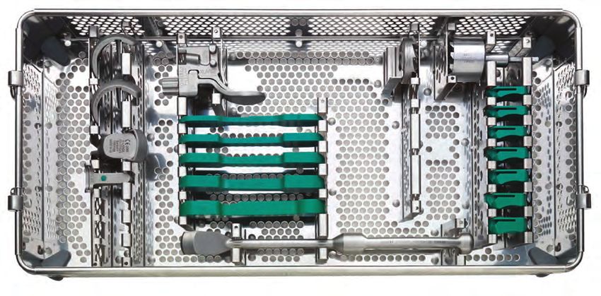
Oxford Partial Knee     ®

Contents

Oxford® Partial Knee......................................................................................................................................................2
        Femoral Components
        Tibial Components
        Meniscal Bearings

Patient Selection...........................................................................................................................................................3
        The Learning Curve
        Preoperative X-ray Template
        Open vs. Minimally Invasive Technique

Positioning the Limb.....................................................................................................................................................7

Incision..........................................................................................................................................................................7

Osteophyte Excision.....................................................................................................................................................8

Tibial Plateau Resection................................................................................................................................................9

The Femoral Drill Holes and Alignment......................................................................................................................12

Femoral Saw Cut.........................................................................................................................................................14

First Milling of the Condyle.........................................................................................................................................16

Equalizing the Flexion and Extension Gaps................................................................................................................17

Confirming Equality of the Flexion and Extension Gaps............................................................................................19

Preventing Impingement.............................................................................................................................................20

Final Preparation of the Tibial Plateau........................................................................................................................22

Final Trial Reduction....................................................................................................................................................24

Cementing the Components.......................................................................................................................................26

Appendix ....................................................................................................................................................................28
        Postoperative Treatment
        Postoperative Radiographic Assessment
        Radiographic Technique
        Radiographic Criteria
        Position and Size of Components
        Follow-up Radiographs

Ordering Information...................................................................................................................................................31

Indications and Full Prescribing Information..............................................................................................................50

This Oxford Partial Knee Twin Peg Femoral Component with Microplasty®
             ®

Instrumentation surgical technique is utilized by K. Berend, M.D., M. Berend, M.D.,
Mr. C. Dodd, Mr. J. Goodfellow, D. Mauerhan, M.D., Prof. D. Murray and
Prof. J. O’Connor. Biomet, as the manufacturer of this device, does not practice
medicine and does not recommend this device or technique. Each surgeon is
responsible for determining the appropriate device and technique to utilize on each
individual patient.

                                                                                                                                                                                  1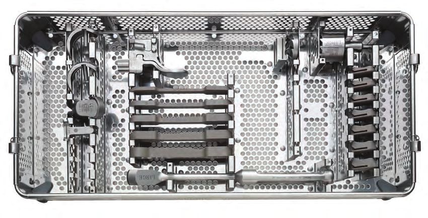
Oxford Partial Knee
                 ®

Introduction                                                      Tibial Components
The Oxford® Partial Knee is the natural evolution of the          The tibial components, also made of cast cobalt chromium
original meniscal arthroplasty, which was first used in           molybdenum alloy, are available in seven sizes, both right
1976.1 It continues to offer the advantage of a large area        and left. Their shapes are designed to provide optimal
of contact throughout the entire range of movement for            bone coverage while avoiding component overhang
minimal polyethylene wear, as seen in the Oxford® Partial         anteriomedially.
Knee Phase I and II.2–4

Since 1982, the Oxford® Partial Knee has been successfully
used to treat anteromedial osteoarthritis.4–5 If performed        Meniscal Bearings
early in this disease process, the operation can slow the         The bearings are direct compression molded ultra high
progression of arthritis in the other compartments of the         molecular weight polyethylene (UHMWPE), manufactured
joint and provide long-term symptom relief.6                      from ArCom® direct compression molded polyethylene for
                                                                  increased wear resistance.8,9
The Oxford® implant is based on its clinically successful
predecessors (Phase 1 and Phase 2) which achieved                 There are five bearing sizes to match the radii of curvature
survivorship rates of 98 percent at 10 years,5,7 with an          of the five femoral component sizes. For each size, there is
average wear rate of 0.03 mm per year.2,3                         a range of seven thicknesses, from 3 mm to 9 mm.

Femoral Components
The unique, spherically designed femoral components
are made of cast cobalt chromium molybdenum alloy for
strength, wear resistance and biocompatibility. The design
is available in five sizes to provide an optimal fit. The sizes
are parametric and have corresponding radii of curvature.

The articulating surface of the femoral component is
spherical and polished to a very high tolerance. The
appropriate size of femoral component is chosen based
on the patient size, pre-operative templating of lateral
radiographs and intra-operative measurement confirmed
with sizing spoons.

2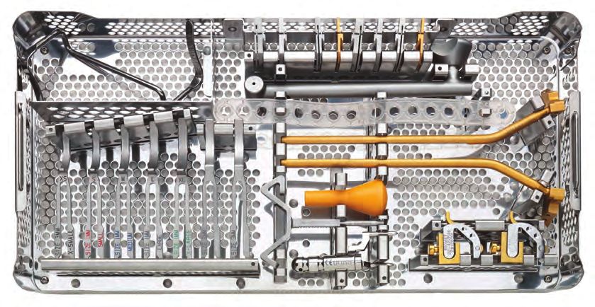
Patient Selection

There are well-defined circumstances in which the Oxford®     • Posterior bone loss on a lateral radiograph or mediolateral
Partial Knee for medial arthroplasty is appropriate and         subluxation that does not correct on valgus stress
certain criteria must be fulfilled for success:                 radiographs strongly suggests damage to the anterior
                                                                cruciate ligament (ACL).11 If there is doubt about the
• The operation is indicated for the treatment of               integrity of the ACL it should be assessed with a hook
  anteromedial osteoarthritis.4                                 during the operation.

                                                              • The lateral compartment should be well preserved,
          Posterior
                                                                with an intact meniscus and full thickness of articular
                                                                cartilage. This is best demonstrated by the presence of
                                                                a full thickness ‘joint space’ visible on an A/P radiograph
                                                                taken with the joint stressed into valgus.12 However,
                                                                a grade 1 cartilage defect, marginal osteophytes and
                                                                localized areas of erosion of the cartilage on the
                                                                medial side of the lateral condyle are frequently seen
                                                                during surgery and are not contraindications to medial
                                                                compartment arthroplasty.

                                                              • The intra-articular varus deformity must be passively
                                                                correctable to pre-disease status and not beyond. A
                                                                good way to confirm this is to take valgus stressed
                                                                radiographs.

                                                              • The degree of intra-articular deformity is not as important
                                                                as its ability to be passively corrected by the application of
                                                                a valgus force. Varus deformity of more than 15 degrees
                                                                can seldom be passively corrected to neutral; therefore,
                                                                this figure represents the outer limit. Soft tissue release
                                                                should never be performed. If the medial collateral
                                                                ligament has shortened and passive correction of the
           Anterior                                             varus is impossible, the arthritic process has progressed
                                                                beyond the suitable stage for this procedure, and thus
                          Figure 1
                                                                the procedure is contraindicated.

• There must be full thickness cartilage loss on both sides   • Flexion deformity should be less than 15 degrees. If it is
  of the medial compartment with bone on bone contact           greater than 15 degrees the ACL is usually ruptured.
  (Figure 1). This may be demonstrated radiographically
  (weight bearing A/P, Rosenberg or varus stress) or          • The knee must be able to flex to at least 110 degrees
  arthroscopically. The results of replacement for partial      under anesthetic to allow access for preparation of the
  thickness cartilage loss are unpredictable.10                 femoral condyle.

• Both cruciate ligaments must be functionally intact. The    • The state of the patello-femoral joint (PFJ) is not
  posterior cruciate is seldom diseased in osteoarthritic       a contraindication provided there is not severe
  knees, but the anterior cruciate is often damaged and is      damage to the lateral part of the PFJ with bone
  sometimes absent. This deficiency is a contraindication       loss, grooving or subluxation. Neither the presence of
  to the procedure.                                             pre-operative anterior knee pain or cartilage loss in the
                                                                PFJ have been shown to compromise the outcome.13
                                                                Similar arthritis in the medial part of the PFJ, however
                                                                severe, or early arthritis in the lateral part of the PFJ have
                                                                not compromised the outcome in reported studies.13–15
                                                                                                                            3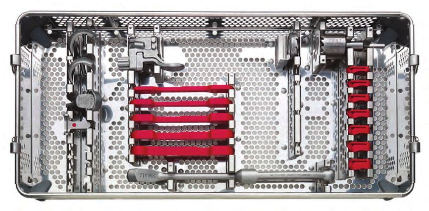
Patient Selection

                                                               The Learning Curve
• Neither the patient’s age, weight nor activity level         This surgical technique should be used in association
  are contraindications, nor is the presence of                with the instructional video of the operation. As with other
  chondrocalcinosis.14–16                                      surgical procedures, errors of technique are more likely
                                                               when the method is being learned. To reduce these to
• Unicompartmental arthroplasty is contraindicated in          a minimum, surgeons are required by the FDA in the
  all forms of inflammatory arthritis. (The pathological       United States, and strongly recommended throughout
  changes of early rheumatoid arthritis can be confused        the world, to attend an Advanced Instructional
  with those of medial compartment osteoarthritis). The        Course on the Oxford® Partial Knee before attempting
  high success rates reported5,6 were achieved in patients     the operation. Masters Courses are also offered
  with anteromedial osteoarthritis, and they may not be        to enhance skills through round-table discussions,
  achieved with other diagnoses. The Oxford® implant has       technical tips, surgical issues, case studies and
  also been used successfully in the treatment of primary      presentations.
  avascular necrosis, but the numbers are too few to be
  statistically significant.

• The Oxford® medial arthroplasty is not designed for and is
  contraindicated for lateral compartment replacement. The
  ligaments of the lateral compartment are more elastic than
  those of the medial, and early dislocation of the bearing
  has been reported. Access through a small incision is
  more difficult laterally than medially. The Vanguard M™
  series fixed bearing unicompartmental replacement is
  an available option for lateral compartment arthroplasty.

• The final decision whether or not to perform
  unicompartmental arthroplasty is made when the knee
  has been opened and directly inspected.

4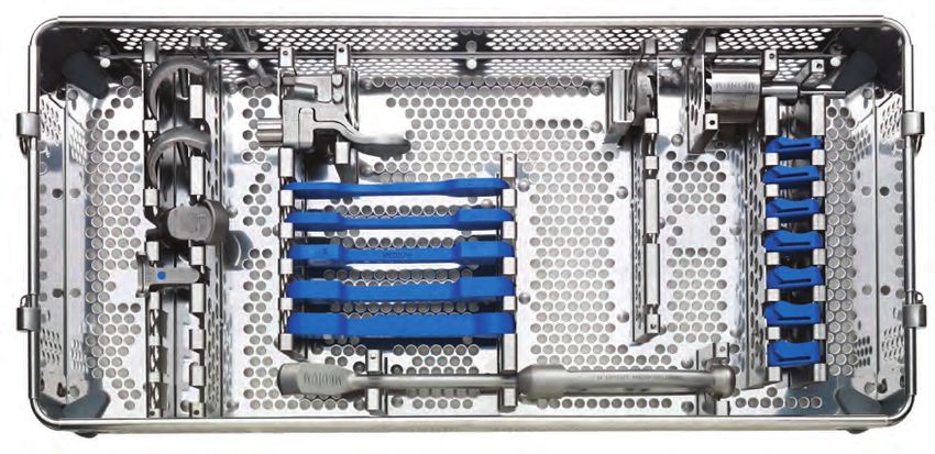
Preoperative X-ray Template
The size of femoral component can be chosen                    Apply the outlines on the template to the X-ray image of
preoperatively using X-ray templates (Figure 2). A true        the medial femoral condyle. The line along the central peg
lateral radiograph is required to accurately template.         of the implant should be 10 degrees flexed compared
                                                               to the long axis of the femoral shaft. The outer surface
                                                               of the diagrammatic component should lie about 2 mm
                                                               outside the radiographic image to allow for the thickness
                                                               of articular cartilage. For a correctly sized implant the
                                                               proximal part of the prosthesis should be approximately
                                                               2 mm outside the bone surface of the proximal part of
                                                               the condyle so the implant surface and retained proximal
                                                               cartilage are flush (Figure 3).

                          Figure 2                                                       Figure 3

Available templates allow for magnification of 105 and         A medium size femoral component is appropriate for most
115 percent. To achieve this the patient should lie on their   patients. In fact, it was the only size used in the Phase I
side with the affected knee resting against the X-ray plate    and II implants.
and the X-ray tube being about 1 m away.
                                                               However, it is better to employ the small size in small
                                                               women and the large size in large men. The extra large is
                                                               only needed in very large men. If there is doubt between
                                                               small/medium or medium/large, it is usually best to use
                                                               the medium. The extra small should only be used in very
                                                               small women.

                                                                                                                        5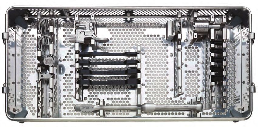
Patient Selection

Open vs. Minimally
Invasive Technique
One advantage of unicompartmental arthroplasty is that
it can be performed through a small incision without
dislocating the patella, thus avoiding damage to the
synovial reflections of the suprapatellar pouch. This can
reduce postoperative pain and allow a more complete
and rapid recovery of flexion. With proper use of the
Oxford® Partial Knee instrumentation, the operation can
be performed through a small incision with great precision.
However, surgeons learning the procedure can extend the
soft tissue incision beyond the limits described here with
very little increase in postoperative morbidity as long as the
integrity of the suprapatellar pouch is preserved.

The open approach, with dislocation of the patella,
is not recommended. The Oxford® Partial Knee
instrumentation is designed for use through a small
incision, and intraoperative dislocation of the patella
distorts the ligaments, possibly making the operation
more difficult.

6
Oxford Partial Knee
                 ®

                                           110˚

                           Figure 4                                                          Figure 5

Positioning the Limb                                              Incision
Inflate a thigh tourniquet and place the draped leg on a          With the knee flexed to 90 degrees, make a medial
thigh support, with the hip flexed to about 30 degrees            parapatellar skin incision from the medial margin of the
and the leg dependent. The knee must be free to flex              patella to a point 3 cm distal to the joint line (Figure 5).
fully and the leg should hang with the knee flexed about          Deepen the incision through the joint capsule. At its upper
110 degrees (Figure 4). The thigh support must not be             end, the capsular incision should extend proximally about
placed in the popliteal fossa as this will increase the risk of   2 cm into the vastus medialis. It should pass around the
damage to the popliteal vessels.                                  patella and down beside the patella tendon.

                                                                  Expose the front of the tibia in the lower part of the
                                                                  wound from the tibial tubercle to the antero-medial rim of
                                                                  the plateau. Excise as much of the medial meniscus as
                                                                  possible. Do not ‘release’ any of the fibers of the medial
                                                                  collateral ligament.

                                                                  Surgeons who are learning the technique should make a
                                                                  larger incision to improve the exposure. The patella should
                                                                  be subluxed but not dislocated.

                                                                  Excise part of the retropatellar fat pad and insert retractors
                                                                  into the synovial cavity. The ACL can now be inspected to
                                                                  ascertain that it is intact. (Absence of a functioning ACL is
                                                                  a contraindication. If this is found, the operation should be
                                                                  abandoned in favor of a total knee replacement).
                                                                                                                              7
Oxford Partial Knee
                 ®

                           Figure 6                                                        Figure 7

Osteophyte Excision
All osteophytes must be removed from the medial margin           With a narrow chisel (6 mm), remove the osteophytes
of the medial femoral condyle and from both margins of the       from beneath the medial collateral ligament (Figure 7) and
intercondylar notch (Figure 6). The assistant extends and        from the posterolateral margin of the medial condyle. This
flexes the knee, moving the incision up and down, allowing       creates room to insert the saw blade into the intercondylar
the various osteophytes to come into view. Osteophytes           notch during the next step.
on the tibial plateau in front of the insertion of the ACL and
in the top of the notch must be removed to allow the fixed
flexion deformity to correct. If there are large osteophytes
around the patella they should also be removed.

8
2c
m
Figure 8 Figure 9
Tibial Plateau Resection
With the knee in flexion, insert the femoral sizing spoon resection. Select either the 3 or the 4 G-clamp and apply
(based on pre-operative estimate sizing) starting with to the femoral sizing spoon and to the medial side of the
1 mm spoon. With all retraction removed, assess the tibial saw guide to ensure access to pin holes.
ligament tension. Usually the 1 mm thick femoral sizing
spoon achieves the proper ligament tension, but if it Manipulate the upper end of the guide so that its face lies
does not replace it with a thicker sizing spoon until the against the exposed bone. A recess accommodates the
proper tension is achieved. The optimal size of the femoral skin and the patellar tendon laterally (Figure 9). Engage
component is confirmed by examining the relationship the cam, by pulling the lever downwards, to lock the three
of the front of the spoon and an estimate of where the components together.
cartilage surface would have been before the arthritis. The
correct sizing spoon should be inserted centrally in the Once the G-clamp is locked holding the femoral sizing
medial compartment. spoon and tibial saw guide in place, pin the guide.
Apply the tibial saw guide with its shaft parallel with the Note: When pinning the guide, the two medial pin holes
long axis of the tibia in both planes (Figures 8 and 9). may be used to secure the guide utilizing one headed
The ankle piece should be pointing towards the anterior and one headless pin, or the single hole directly anterior
superior iliac spine and the standard 0 mm tibial shim to the shaft may be pinned to minimize the number of
should be used. The tibial saw guide has 7 degrees of perforations in the tibial bone.
posterior slope built in.
Once the tibial saw guide is pinned in place, unlock the
The femoral sizing spoon, tibial saw guide and G-clamp, G-clamp and remove along with the femoral sizing spoon.
when used together, will accurately establish the bony
9Oxford Partial Knee
®
Figure 10 Figure 11
Tibial Plateau Resection (cont.)
Confirm the proposed level of resection is correct. The The saw must reach the back of the tibial plateau and a
saw cut should pass 2 or 3 mm below the deepest part of little beyond. This is achieved by lining up the appropriate
the erosion, unless the erosion is very deep in which case mark on the saw with the anterior cortex. Advance the saw
the cut should be above the bottom of the defect. vertically down until it rests on the surface of the saw guide
(Figure 11). The saw must remain parallel to the guide. Do
Use a reciprocating saw with a stiff narrow blade to make not lift the saw handle as this will dip the saw blade and
the vertical tibial saw cut. The Oxford® Saw Blade Kit increase the risk of tibial plateau fracture.
contains blades with markings to indicate the depth to
safely divide the posterior cortex. Push the blade into
the intercondylar notch close to the lateral margin of the
medial femoral condyle, from which the osteophytes were
removed previously. The saw cut should be just medial
to the apex of the medial tibial spine. It will pass through
the edge of the ACL insertion. Point the blade toward the
anterior superior iliac spine or flexion plane (Figure 10).
10Posterior
Anterior
Figure 12 Figure 13
Before making the horizontal cut, insert a medial collateral The excised plateau should show the classical lesion
ligament (MCL) retractor. Ensure this retractor is between of anteromedial osteoarthritis, erosion of cartilage and
the saw and the MCL. bone in its mid and anterior parts and preserved cartilage
posteriorly (Figure 13). Osteophytes around the edge of
Use a 12 mm wide oscillating saw blade with appropriate the plateau remain attached after its removal.
markings to excise the plateau (Figure 12). Ensure the saw
blade is guided along the MCL retractor to completely cut Lay tibial templates of the opposite side on the cut surface
the medial cortex. To cut the posterior cortex, deepen the of the excised plateau to choose the tibial component with
cut until the appropriate mark on the saw blade is aligned the appropriate width.
with the anterior cortex. When the plateau is loose, lever
it up with a broad osteotome and remove. Soft tissue If the tibial component of the appropriate width appears
attachments posteromedially may need to be cut with short, consider repeating the vertical cut 2 or 3 mm further
a knife. lateral so that a wider (and longer) component may be used.
Note: When making the horizontal cut a slotted shim may
be used. This can be done by replacing the standard shim
with the corresponding slotted shim. The slotted shim
helps maintain the 7 degree posterior slope during the
resection.
11Oxford Partial Knee
®
Figure 14 Figure 15 Figure 16
The Femoral Drill Holes
and Alignment
With the knee in about 45 degrees flexion, make a hole in Insert the intramedullary (IM) rod until it stops against the
the intramedullary canal of the femur with the 4 mm drill. bone (Figure 16).
This should be completed with the 5 mm awl (Figure 14).
Flex the knee to 90 degrees. This must be done with care,
The hole must be situated 1 cm anterior to the anterior as the medial border of the patella abuts the IM rod. Using
edge and just medial to the medial wall of the intercondylar methylene blue or diathermy, draw a line down the center
notch (Figure 15). It should aim for the anterior superior of the medial condyle.
iliac spine.
12Figure 17 Figure 18
Insert the femoral drill guide to assess the thickness of the Insert the IM link into the IM rod and into the nearside/
gap (Figure 17). lateral hole of the femoral drill guide. This will ensure
correct alignment of the guide.
The thickness of bone removed from the tibia must be
enough to accommodate the femoral drill guide set at a There are two alignment requirements for the femoral drill
3 or 4. If a 3 G-clamp was used, the gap must be large guide:
enough to accept the femoral drill guide set to 3. If the 1. The femoral drill guide must lie in the center of the
4 G-clamp was used, the gap must be large enough to medial condyle. This is done by ensuring the medial
accept the femoral drill guide set to 4. and lateral bollards adjacent to the 6 mm hole of
Note: Whenever using the femoral drill guide or feeler the femoral drill guide are equal distance from the
gauges to gap measure the retractors must be removed. condyle edges. It can be confirmed by looking into
If left in, they have the effect of tightening the soft tissues, the 6 mm hole and verifying the position of the
which artificially diminishes the gap. methylene blue line. If the line is not central adjust the
guide position (Figure 18).
If the correctly adjusted femoral drill guide cannot be 2. The femoral drill guide must be placed against the
inserted or feels tight, more bone must be excised from the distal bone of the medial femoral condyle.
tibia. To do this, remove the initial 0 mm shim from the guide
using the small nub on the Oxford IM Rod Removal Hook. Pass the 4 mm drill through the upper hole in the guide.
Once the shim is removed, revisit the vertical resection, Drill into the bone up to its stop and leave in place.
then resect off the surface of the guide without the shim to Confirm all alignments ensuring the guide does not move
remove 2 mm of additional bone. After additional resection, medially or laterally. Advance the 6 mm drill through the
recheck the gap. lower guide hole until it stops. Remove 4 mm and 6 mm
drill along with the femoral drill guide.
13Oxford Partial Knee
®
Figure 19 Figure 20
Femoral Saw Cut
Insert the posterior resection guide into the drilled holes Remove the guide with the slap hammer, ensuring that it
and tap home (Figure 19). is withdrawn in line with the femoral drill guide holes as to
not damage them. Remove the posterior bone fragment.
Insert a retractor to protect the MCL. Using the 12 mm
broad sagittal saw, excise the posterior femoral condyle. There is now good access to the back of the joint and any
The saw blade should be bent slightly by dropping the remnants of the medial meniscus should be removed. In
saw to ensure it is guided by the underside of the posterior the region of the MCL, a small cuff of meniscus should
resection guide (Figure 20). Take care to avoid damage to be left to protect the MCL from the tibial component. The
the medial collateral and anterior cruciate ligaments. posterior horn should be completely removed.
14Before advancing to the following surgical steps, consult the special note below.
Special Note
The numbers marked on the feeler gauges and the meniscal bearings represent their least thicknesses
in millimeters.
The scale of numbers of the spigots is in 1 mm increments, in an inverse ratio to the thickness of their flanges.
The spigots must be used as described below:
• First Milling
The 0 spigot is designed to automatically remove sufficient bone to allow the femoral component to seat.
This amount varies with the degree of arthritic erosion of the condyle.
• Second Milling
Spigots 1 to 7 allow bone to be removed in measured quantities (in mm) from the level of the first mill cut.
Thus, the number 3 spigot removes 3 mm, the number 4 spigot removes 4 mm, etc.
• Subsequent Milling
If the last spigot used was a number 3, a number 4 spigot will remove an additional 1 mm of bone
(i.e. a total of 4 mm since the first milling). However, if the last spigot used was a number 4, a number 5
spigot is required to remove 1 mm of bone (i.e. a total thickness of 5 mm since the first milling).
Remember: The spigot number represents the total thickness of bone it removes from the level
of the first mill cut.
15Oxford Partial Knee
®
Figure 21 Figure 22 Figure 23
First Milling of the Condyle
Insert the 0 spigot, which has the thickest flange, into By extending the knee slightly and retracting the soft
the large drill hole and tap until the flange abuts the bone tissues, maneuver the spherical cutter onto the spigot
(Figure 21). The 0 spigot is the only spigot that may be (Figure 22) and into the wound so that the teeth touch the
tapped into place. All other spigots should be placed and bone (Figure 23). Take care to avoid trapping soft tissues.
seated by finger pressure.
When milling, push firmly in the direction of the spigot
axis, taking care not to tilt the mill. Mill until the cutter will
no longer advance and the spigot can be seen, in the
window, to have reached its end stop.
If in doubt, continue to mill; the mill cannot continue
beyond the amount permitted by the collar of the
selected spigot.
16Figure 24 Figure 25
Equalizing the Flexion
and Extension Gaps
Remove the mill and the spigot and trim off the bone With the knee in 100 degrees of flexion, carefully insert
protruding from the posterior corners of the condyle that the tibial template and apply the twin peg femoral trial
lie outside the periphery of the cutting teeth (Figure 24). component to the milled condyle, tapping it home with the
These corners should be removed tangentially to the femoral impactor angled at 45 degrees to the femoral axis.
milled surface, taking care not to damage the flat posterior
surface of the condyle. Part A
With the knee in about 100 degrees of flexion carefully
measure the flexion gap with the feeler gauges (Figure 25).
(A previous step has already ensured that the gap
is wide enough to accept at least the 4 mm gauge,
3 mm in small patients). The gauge thickness is correct
when natural tension in the ligaments is achieved. Under
these circumstances, the feeler gauge will easily slide in
and out, but will not tilt. Confirmation of the correct size is
obtained by confirming that a gauge 1 mm thicker is firmly
gripped and 1 mm thinner is loose.
17Oxford Partial Knee
®
Figure 26 Figure 27
Equalizing the Flexion
and Extension Gaps (cont.)
Part B
Remove the feeler gauge. It is important to remove the Subtract the extension gap from the flexion gap
gauge before extending the knee because the extension to calculate additional bone removal. For instance, if
gap is always narrower than the flexion gap at this stage. the flexion gap measured 4 mm and the extension gap
If it is left in place, the gauge may stretch or rupture the 1 mm, then the amount of bone to be milled is 3 mm. To
ligaments as the knee extends. achieve this, insert a 3 spigot and mill until the cutter will
not advance further.
Part C
Measure the extension gap (Figure 26) in 20 degrees of After each milling, it is necessary to remove the remaining
flexion, not full extension. In full extension, the posterior bone on the posterior corners of the condyle. Also, if the
capsule is tight, and its influence gives a false under- circular disc of bone left under the flange of the spigot
measurement. The extension gap is usually less than is more than 1 mm thick, it should be removed by using
4 mm, if the thinnest (1 mm feeler gauge) cannot be the bone collar remover (Figure 27). The reference for the
inserted, the gap is assumed to be 0 mm. spigot will not be lost, as its tip continues to reference off
the bottom of the drill hole.
The formula for balancing the flexion and extension gaps is as follows:
Flexion Gap (mm) – Extension Gap (mm) = Thickness of bone to be milled from femur (mm)
= Spigot number to be used
18Figure 28 Figure 29
Confirming Equality of the
Flexion and Extension Gaps
With the tibial template and the twin peg femoral trial If the extension gap at 20 degrees of flexion is still smaller
component in place, re-measure the flexion and extension than the flexion gap, remove more bone with the mill. This
gaps. They will usually be found to be the same (Figures can be done, 1 mm at a time, by using the sequence of
28 and 29). spigots. In the previous example, an additional 1 mm of
bone could be removed by using a 4 spigot.
Usually the knee is balanced with a 3, 4, or 5 spigot.
19Oxford Partial Knee
®
Figure 30 Figure 31
Preventing Impingement
Trim the anterior and posterior condyle of the femur Leave the anti-impingement guide in place and use the
to reduce the risk of impingement of bone against the osteophyte chisel to remove any posterior osteophytes
bearing in full extension and full flexion. (Figure 31). This should be done medially and laterally as
well as centrally. Remove the guide and any detached
Apply the anti-impingement guide to the condyle and osteophytes. Palpate, with a finger, the proximal part of the
use the anterior mill to remove anterior bone and create condyle to ensure all osteophytes are removed.
clearance for the front of the bearing in full extension.
When milling, push firmly in the direction of the peg axis,
taking care not to tilt the mill. Mill until the cutter will not
advance further (Figure 30).
Ensure that impingement does not occur between the mill
and tibia by adjusting flexion.
20Figure 32 Figure 33
Insert the tibial template, then the twin peg femoral trial Note: Previously, feeler gauges have been used to
and a trial bearing of appropriate size. With the trial measure the gaps because they do not stretch the
components in place, manipulate the knee through full ligaments. The meniscal bearings have a 3 mm high
range of motion to ensure there is no impingement of bone posterior lip which, after multiple insertions, may stretch
against the bearing in full flexion and full extension (Figures the ligaments.
32 and 33).
Ensure the bearing is not hitting the vertical wall. If a
narrow dissector put between the bearing and the wall is
gripped by the bearing, consider redoing the vertical cut
laterally.
Remove the trial components using the appropriate
extractors.
21Oxford Partial Knee
®
Figure 34 Figure 35
Final Preparation
of the Tibial Plateau
Insert the appropriate size tibial template. To ensure the Introduce the keel-cut saw into the front of the slot and
correct size, position the tibial template with its posterior saw until sunk to its shoulder (Figure 35). The saw blade
margin flush with the posterior tibial cortex (Figure 34). is lifted up and down as it is advanced posteriorly. Confirm
This is facilitated by passing the universal removal hook the cut is complete by holding the pin and feeling the saw
over the posterior cortex of the tibia. The tibial template hit the front and back of the keel slot. Once the saw cuts
should be flush with the medial cortex or overhanging are complete, remove the tibial template.
slightly. If it overhangs by 2 mm or more use a smaller size
tibial component.
Force the tibial plateau laterally against the vertical cut and
pin in place. Hold the pin throughout sawing to prevent
movement.
22Figure 36 Figure 37
After removing the tibial template, excavate the groove to Insert the trial tibial component and tap with the tibial
the correct depth by scooping out the bone with the blade impactor until fully seated (Figure 37).
of the tibial gouge, taking care not to damage the anterior
and posterior cortices (Figure 36). Ensure component is flush with the bone and the posterior
margin extends to the back of the tibia. If the component
The safest way to prepare the back of the groove is to feel does not seat fully remove it and clean the keel slot out
the posterior cortex with the tibial keel pick and then move again with the tibial gouge.
it anteriorly by 5 mm before pushing down and bringing
forward to empty the groove. Use only the toffee hammer to avoid the risk of plateau
fracture.
23Oxford Partial Knee
®
Figure 38 Figure 39
Final Trial Reduction
Insert the femoral trial component and ensure it is fully Insert a trial meniscal bearing of the chosen thickness
seated by tapping home with the femoral impactor at 45 (Figure 39).
degrees to the femoral axis (Figure 38).
24Figure 40
With the bearing in place, manipulate the knee through a This test should be done with the knee in 20 degrees of
full range of motion to demonstrate stability of the joint, flexion. In full extension, the bearing will be firmly gripped
security of the bearing and absence of impingement. The because of the tight posterior capsule.
thickness of the bearing should be such as to restore the
ligaments to their natural tension so that, when a valgus Remove the bearing with the bearing extractor (Figure 40).
force is applied to the knee, the artificial joint surfaces
distract a millimeter or two.
25Oxford Partial Knee
®
Figure 41
Cementing the Components
Roughen the femoral and tibial surfaces including the Use the right-angled tibial impactor with a small mallet to
posterior condyles, by making multiple small drill holes complete the insertion. Ensure there is no soft tissue under
with the cement key drill (Figure 41). the component. Remove excess cement with a Woodson
cement currette from the margins of the component.
The components are fixed with two separate mixes of Insert the twin peg femoral trial component and pressurize
cement. cement by inserting the appropriate feeler gauge. With the
feeler gauge inserted, hold the leg in 45 degrees of flexion
The Tibial Component while the cement sets. Do not fully extend or flex the leg,
Place a small amount of cement on the tibial bone surface as this may rock the component.
and flatten to produce a thin layer covering the whole
under surface. Insert the component and press down, Once the cement has set, remove the feeler gauge and
first posteriorly and then anteriorly, to squeeze out excess twin peg femoral trial component and look carefully for
cement at the front. cement that may have extruded. Slide the flat plastic
probe along the tibial articular surface, feeling for cement
at the edges and posteriorly.
26Figure 42 Figure 43
The Femoral Component
From the second mix, force cement into the large femoral Once the cement has set, remove the feeler gauge. Clear
drill hole and fill the concave surface of the femoral the medial and lateral margins of the component of any
component with cement. Apply the loaded component to extruded cement. The posterior margin cannot be seen
the condyle and impact with the punch held at 45 degrees but can be palpated with a curved dissector.
to the long axis of the femur. Remove excess cement from
the margins with a Woodson cement currette. Pressurize Reassess the gap by inserting a trial bearing. Occasionally
the cement by inserting the appropriate feeler gauge with a smaller size is needed due to gap closure from the
the knee at 45 degrees of flexion and holding the leg in this cement mantle.
position. Do not fully extend or flex the knee or this may
rock the components and may loosen them. Complete the reconstruction by snapping the chosen
bearing into place (Figures 42 and 43).
Close the wound in a routine manner.
27Appendix
Postoperative Treatment
Forcing flexion of the knee during the first postoperative
week often causes pain and is unnecessary since
movements are almost always recovered spontaneously.
Postoperative Radiographic
Assessment
Postoperative radiographs can be used to measure the
technical success of the operation. For this purpose,
as well as to facilitate their comparison with follow-up
radiographs, the films should be taken in a reproducible
manner. Even small variations in the angle of incidence of
the X-ray beam can distort the images of the components
and make accurate assessment of their positions and
bone/cement interfaces difficult.6
Radiographic Technique
Accurately aligned radiographs are best taken with an
image intensifier (fluoroscope). If this is not available, a
digital system can be used. Low dose images are taken
and then adjusted until the optimal image is obtained.
Anterior Projection
The shape of the tibial component allows it to be used to
center the X-ray beam and to align it in all three planes.
Position the patient supine on a standard fluoroscopic
screening table with an undercouch tube and an image
intensifier. Before taking the film, adjust the position of the
limb by flexing/extending the knee and internally/externally
rotating the leg until the tibial component appears on the
screen directly ‘end-on.’
Figure 44
Lateral Projection
With the leg flexed 40 degrees, internally/externally rotate
the thigh until the tibial component appears on the screen
directly ‘edge-on.’
The components ideally implanted are shown in Figure 44.
28Appendix
Radiographic Criteria
If all steps have been followed as described in this surgical
technique, the postoperative appearances should be as shown
A
in Figure 45.
Position and Size of Components
Femoral Component (Relative to the Femur) C C
A/A Varus/valgus angle < 10 degrees varus — < 10 degrees valgus
L
B/B Flexion/extension angle 15 degrees flexion — < 0 degrees K
E E
extension
N
C/C Medial/lateral placement Central P
D Posterior fit Flush or < 4 mm overhang P
A
Tibial Component (Relative to the Tibia) G
E/E Varus/valgus angle < 5 degrees varus — < 5 degrees valgus
F/F Posteroinferior tilt 7 degrees +or- 5 degrees
G Medial fit Flush or < 2 mm overhang
H Posterior fit Flush or < 2 mm overhang
J Anterior fit Flush or < 5 mm short
K Lateral fit Flush — No gap
B
Meniscal Bearing
(Relative to the Tibial Component)
L X-ray marker central and parallel with the tibial component
O
Bone Interfaces
M Posterior femoral Parallel surfaces: Cement OK D
R M
N Tibial Parallel surfaces: Cement OK
B
Other F
O Posterior osteophytes None visible F
P Depth of tibial saw cuts Minimal ingress of cement
Q
Q Intact posterior cortex No extruded cement posteriorly
R No anterior Adequate bone removed; no cement
impingement H
J
Figure 45
29Appendix Follow-up Radiographs All subsequent radiographs should be taken in the same manner as the immediate postoperative films to allow comparison. Fluoroscopically centered films are particularly appropriate for demonstrating the state of the interface beneath the tibial plateau. This interface changes gradually during the first year after implantation, after which it should remain unaltered. The typical appearance at one year and ten years is a thin radiolucent line (approximately 1 mm). Histologically, the radiolucent line represents a layer of fibrocartilage, with its collagen organized parallel with the plateau. The radiodense line represents a new ‘subchondral bone plate.’ The trabeculae, which were cut at the operation, attach to this plate and support it. The collagen fibers of the cartilage layer insert into its upper surface.17 There are some areas within the radiolucency in which there is direct contact between cement and bone. The appearances under the femoral component are the same, but are not easily demonstrated because of the non-planar form of the femoral interface. The radiographic changes which occur during the first postoperative year result from healing of the cut bone and its remodeling to sustain the new pattern of compressive load applied to it by the rigid implant. Mature interfaces of this type have proven stable for as long as 15 years in 95 percent of cases (Phase II).6 Therefore it is important not to ascribe clinical symptoms to these ‘normal’ appearances or to interpret them as evidence of implant loosening, i.e. radiolucent line. 30
Oxford Partial Knee
            ®

Implants
Femoral Components
            Product              Part Number                         Description                        Size

                                   161467           Oxford®   Twin   Peg   Femoral   Component         X-small
                                   161468           Oxford®   Twin   Peg   Femoral   Component          Small
                                   161469           Oxford®   Twin   Peg   Femoral   Component         Medium
                                   161470           Oxford®   Twin   Peg   Femoral   Component          Large
                                   161471           Oxford®   Twin   Peg   Femoral   Component         X-large

Tibial Components
            Product              Part Number                          Description                            Size
                                   159531           Oxford Tibial Component, Left Medial
                                                              ®
                                                                                                             AA
                                   159532           Oxford® Tibial Component, Right Medial                   AA
                                   154718           Oxford® Tibial Component, Left Medial                     A
                                   154719           Oxford® Tibial Component, Right Medial                    A
                                   154720           Oxford® Tibial Component, Left Medial                    B
                                   154721           Oxford® Tibial Component, Right Medial                   B
                                   154722           Oxford® Tibial Component, Left Medial                    C
                                   154723           Oxford® Tibial Component, Right Medial                   C
                                   154724           Oxford® Tibial Component, Left Medial                    D
                                   154725           Oxford® Tibial Component, Right Medial                   D
                                   154726           Oxford® Tibial Component, Left Medial                     E
                                   154727           Oxford® Tibial Component, Right Medial                    E
                                   154775           Oxford® Tibial Component, Left Medial                     F
                                   154776           Oxford® Tibial Component, Right Medial                    F

Tibial Bearings
      Product                            Part Number                                           Description
                      X-small   Small      Medium       Large          X-large           Thickness             Side
                      159790    159540     159547      159554          159561              3   mm
                      159791    159541     159548      159555          159562              4   mm
                      159792    159542     159549      159556          159563              5   mm
                      159793    159543     159550      159557          159564              6   mm                 Left
                      159794    159544     159551      159558          159565              7   mm
                      159795    159545     159552      159559          159566              8   mm
                      159796    159546     159553      159560          159567              9   mm
                      160790    159568     159575      159582          159589              3   mm
                      160791    159569     159576      159583          159590              4   mm
                      160792    159570     159577      159584          159591              5   mm
                      160793    159571     159578      159585          159592              6   mm              Right
                      160794    159572     159579      159586          159593              7   mm
                      160795    159573     159580      159587          159594              8   mm
                      160796    159574     159581      159588          159595              9   mm

                                                                                                                         31
Oxford Partial Knee Instrumentation
®
32-423539 Tibial Case 1—Upper Insert Tray
B
C
A
D
E
G
H
F
Product Label Part Number Description Size
32-423539 Oxford Microplasty Instrument Tray (Tray Only)
®
–
32-421066 Oxford® Tibial Template Left Medial AA
32-421067 Oxford® Tibial Template Right Medial AA
32-420825 Oxford® Tibial Template Left Medial A
32-420826 Oxford® Tibial Template Right Medial A
32-420056 Oxford® Tibial Template Left Medial B
32-420057 Oxford® Tibial Template Right Medial B
32-420058 Oxford® Tibial Template Left Medial C
A
32-420059 Oxford® Tibial Template Right Medial C
32-420060 Oxford® Tibial Template Left Medial D
32-420061 Oxford® Tibial Template Right Medial D
32-420062 Oxford® Tibial Template Left Medial E
32-420063 Oxford® Tibial Template Right Medial E
32-420827 Oxford® Tibial Template Left Medial F
32-420828 Oxford® Tibial Template Right Medial F
B 32-467619 Quick-Release Drill Bit (PK/2) –
C 32-420802 Tibial Resection Headless Pin (PK/2) –
D 32-347911 Bone Pin (PK/2) –
32Product Label Part Number Description Size
E 32-420160 Pin Inserter/Extractor –
F 32-422455 Oxford® Tibial Template Nail –
32-421064 Oxford® Tibial Trial Left Medial AA
32-421065 Oxford® Tibial Trial Right Medial AA
32-420820 Oxford® Tibial Trial Left Medial A
32-420821 Oxford® Tibial Trial Right Medial A
32-420730 Oxford® Tibial Trial Left Medial B
32-420731 Oxford® Tibial Trial Right Medial B
32-420732 Oxford® Tibial Trial Left Medial C
G
32-420733 Oxford® Tibial Trial Right Medial C
32-420734 Oxford® Tibial Trial Left Medial D
32-420735 Oxford® Tibial Trial Right Medial D
32-420736 Oxford® Tibial Trial Left Medial E
32-420737 Oxford® Tibial Trial Right Medial E
32-420822 Oxford® Tibial Trial Left Medial F
32-420823 Oxford® Tibial Trial Right Medial F
H 32-467618 AGC® Quick Release Drill Chuck –
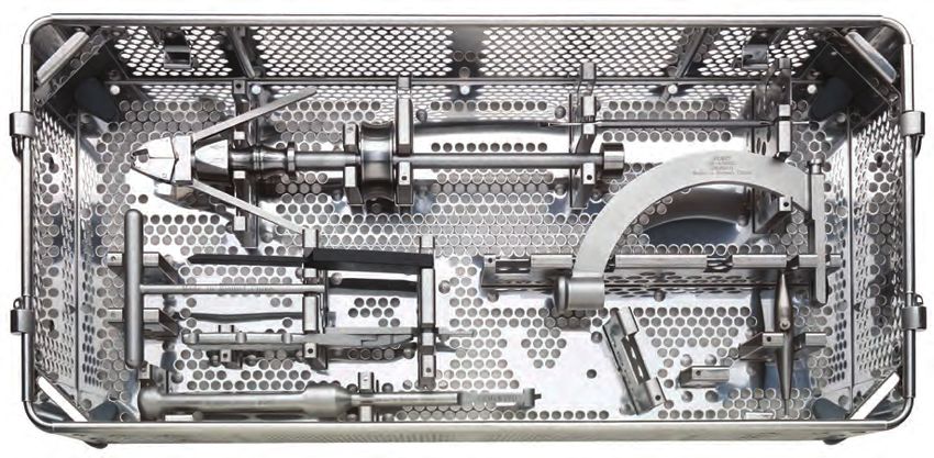
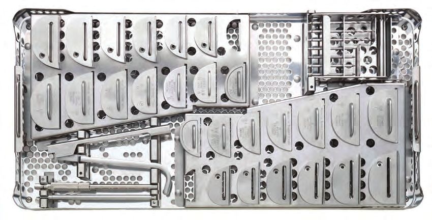
33Oxford Partial Knee Instrumentation
®
32-423539 Tibial Case 1—Lower Insert Tray
B
A
C
D
E
G
F
H
Product Label Part Number Description Size
32-423539 Oxford Microplasty Instrument Tray (Tray Only)
®
–
A 32-422365 Oxford® Slap hammer –
B 32-422991 Woodson Cement Curette –
C 32-420932 Oxford® Tibial Impactor –
D 32-420804 Oxford® Cement Removal Chisel –
E 32-401111 Oxford® IM Rod Removal Hook –
34Product Label Part Number Description Size
F 32-422718 Oxford® Trial Tibial Bearing Inserter/Extractor –
G 32-420660 Oxford® Hex Driver –
H 32-422936 Oxford® Tibial Groove Cutter (Cemented) –
35Oxford Partial Knee Instrumentation
®
32-423540 Tibial Case 2—Upper Insert Tray
B
A
C
D
C
E F
G
I
H
Product Label Part Number Description Size
32-423540 Oxford Microplasty Instrument Tray (Tray Only)
® ®
–
A 3000-02 MCL Retractor –
32-422985 Oxford® Tibial Shim, Right Medial 0 mm
32-423223 Oxford® Slotted Tibial Shim, Right Medial 0 mm
32-422987 Oxford® Tibial Shim, Right Medial 2 mm
32-423230 Oxford® Slotted Tibial Shim, Right Medial 2 mm
B
32-423231 Oxford® Slotted Tibial Shim, Left Medial 2 mm
32-422990 Oxford® Tibial Shim, Left Medial 2 mm
32-423222 Oxford® Slotted Tibial Shim, Left Medial 0 mm
32-422988 Oxford® Tibial Shim, Left Medial 0 mm
C 32-423200 Oxford® Microplasty® Tibial Resector Body Tube –
D 32-422778 Oxford® Silicone Ankle Strap –
32-422828 1 mm
32-422792 1 mm
32-422795 1 mm
E 32-422798 Oxford® Tibial Gap Sizing Spoon 1 mm
32-422839 1 mm
32-423285 2 mm
32-423286 3 mm
F 32-422848 Oxford® IM Rod Pusher –
36Product Label Part Number Description Size
G 32-422777 Ankle Yoke –
H 32-422822 Oxford® IM Link –
32-422846 3 mm
I Oxford® Tibial Resector Stylus
32-422863 4 mm
37Oxford Partial Knee Instrumentation
®
32-423540 Tibial Case 2—Lower Insert Tray
N
B
A C
Q
D
E
F
G
P
H
I K
J O L
M
Product Label Part Number Description Size
32-423540 Oxford Microplasty Instrument Tray (Tray Only)
® ®
–
A 32-423232 Oxford® Anterior Bone Removal Shaft (Outer) –
B 32-422984 Cannulated IM rod 300 mm
C 32-422847 Cannulated IM rod 200 mm
D 32-420127 Femoral Impactor –
E 32-423233 Oxford® Anterior Bone Removal Shaft (Inner) –
F 32-423226 Concise Oxford® IM Awl 5 mm
G 32-422760 Toffee Hammer –
H 32-423287 Bone Collar Remover –
38Product Label Part Number Description Size
32-420333 7
32-420334 6
32-420335 5
32-420336 4
I Oxford® Spigot
32-420337 3
32-420338 2
32-420339 1
32-420340 0
32-420663 1 mm
J 32-420664 Oxford® Metal Shim 2 mm
32-420665 3 mm
K 32-423227 Oxford® Cement Key Drill –
L 32-423228 Oxford® Quick Release Femoral Drill Bit 4 mm
M 32-422845 Oxford® Quick Release Femoral Drill Bit 6.35 mm
N 42-411400 Signature™ Alignment Rod* –
42-411402 Oxford® Signature™ Tibial Alignment Checker Left*
O –
42-411403 Oxford® Signature™ Tibial Alignment Checker Right*
P 42-411420 Oxford® Signature™ Tibial Drill Guide* –
Q 42-411401 Oxford® Signature™ Femoral Alignment Checker* –
* Not photographed, not a part of standard set definition
39Oxford Partial Knee Instrumentation
®
32-423527 Femoral Instruments — X-small
A C D
B
E
F I
H
G
K
J
Product Label Part Number Description Size
32-423534 Oxford Microplasty Instrument Tray (Tray Only)
® ®
–
A 32-421050 Oxford® Single Peg Femoral Trial X-small
B 32-422974 Oxford® Femoral Drill Guide X-small
C 32-423234 Oxford® Anterior Bone Mill X-small
D 32-421062 Oxford® Spherical Mill X-small
E 32-422952 Oxford® Twin Peg Femoral Trial X-small
F 32-423235 Oxford® Anti-impingement Guide X-small
G 32-422979 Oxford® Posterior Resection Guide X-small
40Product Label Part Number Description Size
32-422766 1/2 mm
32-422767 3/4 mm
H Oxford® Gap Gauge, X-small
32-422768 5/6 mm
32-422769 7/8 mm
32-422693 3 mm
32-422694 4 mm
I 32-422695 Oxford® Trial Bearing, X-small 5 mm
32-422696 6 mm
32-422697 7 mm
J 32-422938 Oxford® Chisel X-small
42-411430 X-small
K Oxford® Signature™ Drill Guides*
42-411431 Small
* Not photographed, not a part of standard set definition
41Oxford Partial Knee Instrumentation
®
32-423528 Femoral Instruments — Small
D
A C
B
E
F I
H
G
K
J
Product Label Part Number Description Size
32-423535 Oxford Microplasty Instrument Tray (Tray Only)
® ®
–
A 32-420341 Oxford® Single Peg Femoral Trial Small
B 32-422975 Oxford® Femoral Drill Guide Small
C 32-423236 Oxford® Anterior Bone Mill Small
D 32-420329 Oxford® Spherical Mill Small
E 32-422953 Oxford® Twin Peg Femoral Trial Small
F 32-423237 Oxford® Anti-impingement Guide Small
G 32-422980 Oxford® Posterior Resection Guide Small
42Product Label Part Number Description Size
32-422771 1/2 mm
32-422801 3/4 mm
H 32-422802 Oxford Gap Gauge, Small
®
5/6 mm
32-422803 7/8 mm
32-422804 9 mm
32-422698 3 mm
32-422699 4 mm
32-422700 5 mm
I 32-422701 Oxford® Trial Bearing, Small 6 mm
32-422702 7 mm
32-422721 8 mm
32-422722 9 mm
J 32-422937 Oxford® Chisel Small
42-411434 Small Downsize
K 42-411435 Oxford Signature Drill Guides*
® ™
Small
42-411436 Small Upsize
* Not photographed, not a part of standard set definition
43Oxford Partial Knee Instrumentation
®
32-423529 Femoral Instruments — Medium
A C D
B
E
F
I
H
G
K
J
Product Label Part Number Description Size
32-423536 Oxford Microplasty Instrument Tray (Tray Only)
® ®
–
A 32-420342 Oxford® Single Peg Femoral Trial Medium
B 32-422976 Oxford® Femoral Drill Guide Medium
C 32-423238 Oxford® Anterior Bone Mill Medium
D 32-420330 Oxford® Spherical Mill Medium
E 32-422954 Oxford® Twin Peg Femoral Trial Medium
Medium
F 32-423239 Oxford® Anti-impingement Guide
G 32-422981 Oxford® Posterior Resection Guide Medium
44Product Label Part Number Description Size
32-422805 1/2 mm
32-422806 3/4 mm
H 32-422807 Oxford Gap Gauge, Medium
®
5/6 mm
32-422808 7/8 mm
32-422809 9 mm
32-422703 3 mm
32-422704 4 mm
32-422705 5 mm
I 32-422706 Oxford® Trial Bearing, Medium 6 mm
32-422707 7 mm
32-422723 8 mm
32-422724 9 mm
J 32-422344 Oxford® Chisel Medium
42-411439 Medium Downsize
K 42-411440 Oxford® Signature™ Drill Guides* Medium
42-411441 Medium Upsize
* Not photographed, not a part of standard set definition
45Oxford Partial Knee Instrumentation
®
32-423530 Femoral Instruments — Large
A C D
B
E
F
I
G H
K
J
Product Label Part Number Description Size
32-423537 Oxford® Microplasty® Instrument Tray (Tray Only) –
A 32-420343 Oxford® Single Peg Femoral Trial Large
B 32-422977 Oxford® Femoral Drill Guide Large
C 32-423240 Oxford® Anterior Bone Mill Large
D 32-420331 Oxford® Spherical Mill Large
E 32-422955 Oxford® Twin Peg Femoral Trial Large
F 32-423241 Oxford® Anti-impingement Guide Large
G 32-422982 Oxford® Posterior Resection Guide Large
46Product Label Part Number Description Size
32-422810 1/2 mm
32-422811 3/4 mm
H 32-422812 Oxford Gap Gauge, Large
®
5/6 mm
32-422813 7/8 mm
32-422814 9 mm
32-422708 3 mm
32-422709 4 mm
32-422710 5 mm
I 32-422711 Oxford® Trial Bearing, Large 6 mm
32-422712 7 mm
32-422725 8 mm
32-422726 9 mm
J 32-422935 Oxford® Chisel Large
42-411444 Large Downsize
K 42-411445 Oxford Signature Drill Guides*
® ™
Large
42-411446 Large Upsize
* Not photographed, not a part of standard set definition
47Oxford Partial Knee Instrumentation
®
32-422759 Femoral Instruments — X-large
D
A C
B
E
F I
G H
K
J
Product Label Part Number Description Size
32-423538 Oxford® Microplasty® Instrument Tray (Tray Only) –
A 32-420344 Oxford® Single Peg Femoral Trial X-large
B 32-422978 Oxford® Femoral Drill Guide X-large
C 32-423242 Oxford® Anterior Bone Mill X-large
D 32-420332 Oxford® Spherical Mill X-large
E 32-422956 Oxford® Twin Peg Femoral Trial X-large
F 32-423243 Oxford® Anti-impingement Guide X-large
G 32-422983 Oxford® Posterior Resection Guide X-large
48Product Label Part Number Description Size
32-422815 1/2 mm
32-422816 3/4 mm
H 32-422817 Oxford Gap Gauge, X-large
®
5/6 mm
32-422818 7/8 mm
32-422819 9 mm
32-422713 3 mm
32-422714 4 mm
32-422715 5 mm
I 32-422716 Oxford® Trial Bearing, X-large 6 mm
32-422717 7 mm
32-422727 8 mm
32-422728 9 mm
J 32-422939 Oxford® Chisel X-large
42-411449 X-large Downsize
K Oxford® Signature™ Drill Guides*
42-411450 X-large
* Not photographed, not a part of standard set definition
49Biomet UK Ltd. Ref: 5401000201 4. Specialised instruments are designed for Biomet joint replacement systems to aid in the
Waterton Industrial Estate Revision: 10 accurate implantation of the prosthetic components. The use of instruments or implant
Bridgend CF31 3XA, UK Date: April 2013 components from any other systems can result in inaccurate fit, sizing, excessive wear and
device failure.
5. Intraoperative fracture or breaking of instruments has been reported. Surgical instruments
OXFORD® PARTIAL KNEE SYSTEM are subject to wear with normal usage. Instruments, which have experienced extensive use
or excessive force, are susceptible to fracture. Surgical instruments should only be used for
ATTENTION OPERATING SURGEON their intended purpose. Biomet recommends that all instruments be regularly inspected for
wear and disfigurement.
DESCRIPTION 6. All trial, packaging, and instrument components must be removed prior to closing the surgi-
The Oxford Partial Knee is a medial partial knee replacement system consisting of a femoral cal site. Do not implant.
component, a tibial component and a freely mobile meniscal bearing.
POSSIBLE ADVERSE EFFECTS
Materials A time-course distribution of the adverse events reported in the clinical investigation of the Oxford
Femoral Component: CoCrMo Alloy Partial Knee using a standard open surgical technique is provided in Table 1.
Tibial Component: CoCrMo Alloy
Meniscal Bearing: Ultra-High Molecular Weight Polyethylene (UHMWPE) Table 1 – Time-Course Distribution of Adverse Events reported in the clinical trial for the Oxford
Marker Wire: Titanium Alloy Partial Knee* using a standard open surgical technique
Marker Balls: Tantalum
Percent of
INDICATIONS Adverse Events Frequency Population1
The Oxford Partial Knee is intended for use in individuals with osteoarthritis or avascular necrosis (n=125)
limited to the medial compartment of the knee and is intended to be implanted with bone cement. Visit IO 6 mo 1 yr 2 yr 3 yr 4 yr >5 yr
CONTRAINDICATIONS Local–Operative Site
Contraindications include:
Effusion 1 0.8%
1. Infection, sepsis, and osteomyelitis.
2. Use in the lateral compartment of the knee. Deep Infection 1 0.8%
3. Rheumatoid arthritis or other forms of inflammatory joint disease.
Degeneration of
4. Revision of a failed prosthesis, failed upper tibial osteotomy or post-traumatic arthritis after 1 3 3.2%
contralateral condyle
tibial plateau fracture.
5. Insufficiency of the collateral, anterior or posterior cruciate ligaments which would preclude Loose body and/or
1 2 1 3.2%
stability of the device. osteophyte removal
6. Disease or damage to the lateral compartment of the knee.
Soft tissue damage 2 1.6%
7. Uncooperative patient or patient with neurologic disorders who are incapable of following
directions. Dislocation 2 1.6%
8. Osteoporosis.
9. Metabolic disorders which may impair bone formation. Component mal-alignment 1 0.8%
10. Osteomalacia. Patella dislocation 1 0.8%
11. Distant foci of infections which may spread to the implant site.
12. Rapid joint destruction, marked bone loss or bone resorption apparent on roentgenogram. Component loosening 1 2 3 4.8%
13. Vascular insufficiency, muscular atrophy, neuromuscular disease. Post-operative
14. Incomplete or deficient soft tissue surrounding the knee. 1 0.8%
bone fracture
15. Charcot’s disease.
16. A fixed varus deformity (not passively correctable) of greater than 15 degrees. Trauma 1 0.8%
17. A flexion deformity greater than 15 degrees. Mechanical symptoms 1 0.8%
WARNINGS Instability 1 0.8%
1. Improper selection, placement, positioning, alignment and fixation of the implant compo-
Persistent pain 1 0.8%
nents may result in unusual stress conditions which may lead to subsequent reduction in the
service life of the prosthetic components. Wear of bearing
1 0.8%
2. Improper preoperative or intraoperative implant handling or damage (scratches, dents, etc.) due to osteophyte
can lead to crevice corrosion, fretting, fatigue fracture and/or excessive wear.
Systemic
3. Do not modify implants.
4. Do not reuse implants. While an implant may appear undamaged, previous stress may have Development of
created imperfections that would reduce the service life of the implant. Do not treat patients 1 0.8%
rheumatoid arthritis
with implants that have been, even momentarily, placed in a different patient. Furthermore,
re-using an implant could cause patient contamination. * Phase 2 device design
5. Malalignment or soft tissue imbalance can place inordinate forces on the components which IO = intraoperatively
may cause excessive wear to the patellar or tibial bearing articulating surfaces. Revision
surgery may be required to prevent component failure.
1
All percentages for adverse events are based the number of occurrences reported in a patient
6. Care is to be taken to ensure complete support of all parts of the device embedded in population of 125 knee cases. Those events listed in italics are considered device related events.
bone cement to prevent stress concentrations, which may lead to failure of the procedure. Boldface numbers represent revisions due to the given adverse event. One additional case was
Complete preclosure cleaning and removal of bone cement debris, metallic debris, and other revised at 130 months post-operatively, cause unknown.
surgical debris at the implant site is critical to minimize wear of the implant articular surfaces.
The following complications have also been reported in the clinical literature for partial and total
Implant fracture and loosening due to cement failure has been reported.
knee arthroplasty designs and could potentially occur with the Oxford Partial Knee device.
7. The surgeon is to be thoroughly familiar with the implants and instruments, prior to perform-
1. Major surgical risks associated with anesthetic including, brain damage, pneumonia, blood
ing surgery.
clots, heart attack, and death.
8. Patients should be warned of the impact of excessive loading that can result if the patient
2. Cardiovascular disorders including venous thrombosis, pulmonary embolism, and myocardial
is involved in an occupation that includes substantial walking, running, lifting, or excessive
infarction.
muscle loading due to weight that place extreme demands on the knee and can result in
3. A sudden drop in blood pressure intraoperatively due to the use of bone cement.
device failure or dislocation.
4. Damage to blood vessels, hematoma, delayed wound healing and/or infection.
9. Patient smoking may result in delayed healing, non-healing and/or compromised stability in
5. Temporary or permanent nerve damage may result in pain and numbness.
or around the placement site.
6. Material sensitivity reactions. Implantation of foreign material in tissues can result in histologi-
10. The surgical technique should be followed. Deviations from the surgical technique could
cal reactions involving various sizes of macrophages and fibroblasts. The clinical significance
result in early loosening/failure of the device, or other adverse events as outlined in the follow-
of this effect is uncertain, as similar changes may occur as a precursor to or during the heal-
ing section. Clinical outcome may be affected by component positioning. Proper placement
ing process.
of the implant should take into consideration individual patient anatomy as well as surgeon
7. Particulate wear debris and discoloration from metallic and polyethylene components of joint
preference. The surgical technique sets forth guidelines for placement of the knee system.
implants may be present in adjacent tissue or fluid. It has been reported that wear debris may
initiate a cellular response resulting in osteolysis or osteolysis may be a result of loosening of
PRECAUTIONS
the implant.
1. As with other surgical procedures, errors of technique are most likely when the method is
8. Early or late postoperative, infection, and allergic reaction.
being learned. To reduce these to a minimum, surgeons are required in the United States
9. Intraoperative bone perforation or fracture may occur, particularly in the presence of poor
and strongly recommended throughout the world, to attend an Instructional Course on the
bone stock caused by osteoporosis, bone defects from previous surgery, bone resorption,
Oxford Partial Knee before attempting the operation.
or while inserting the device.
2. Biomet joint replacement prostheses provide the surgeon with a means of reducing pain and
10. Loosening or migration of the implants can occur due to loss of fixation, trauma, malalign-
restoring function for many patients. While these devices are generally successful in attaining
ment, bone resorption, excessive activity.
these goals they cannot be expected to withstand the activity levels and loads of normal
11. Periarticular calcification or ossification, with or without impediment of joint mobility.
healthy bone and joint tissue.
12. Inadequate range of motion due to improper selection or positioning of components.
3. Accepted practices in postoperative care are important. Failure of the patient to follow
13. Dislocation and subluxation due to inadequate fixation and improper positioning. Muscle and
postoperative care instructions involving rehabilitation can compromise the success of the
fibrous tissue laxity can also contribute to these conditions.
procedure. The patient is to be advised of the limitations of the reconstruction and the need
14. Fatigue fracture of components can occur as a result of loss of fixation, strenuous activity,
for protection of the implants from full load bearing until adequate fixation and healing have
malalignment, trauma, non-union, or excessive weight.
occurred. Excessive, unusual and/or awkward movement and/or activity, trauma, excessive
15. Fretting and crevice corrosion can occur at interfaces between components.
weight, and obesity have been implicated with premature failure of the implant by loosen-
16. Wear and/or deformation of articulating surfaces.
ing, fracture, dislocation, subluxation and/or wear. Loosening of the implants can result
in increased production of wear particles, as well as accelerate damage to bone making
successful revision surgery more difficult. The patient is to be made aware and warned in
advance of general surgical risks, possible adverse effects as listed, and to follow the instruc- Continued on next page.
tions of the treating physician including follow-up visits.
50You can also read