Modbus Ethernet Driver - Kepware
←
→
Page content transcription
If your browser does not render page correctly, please read the page content below
Modbus Ethernet Driver

       © 2020 PTC Inc. All Rights Reserved.
Modbus Ethernet Driver 2
Table of Contents
M odbus Ethernet Driver 1
Table of Contents 2
Modbus Ethernet Driver 5
Overview 5
Supported Device Models 6
Setup 7
Channel Properties — General 8
Channel Properties — Ethernet Communications 9
Channel Properties — Write Optimizations 9
Channel Properties — Advanced 10
Channel Properties — Communication Serialization 11
Channel Properties — Ethernet 12
Device Properties — General 13
Device Properties — Scan Mode 15
Device Properties — Timing 15
Device Properties — Auto-Demotion 16
Device Properties — Tag Generation 17
Device Properties — Variable Import Settings 19
Device Properties — Unsolicited 19
Modbus Master & Modbus Unsolicited Considerations 20
Device Properties — Error Handling 21
Device Properties — Ethernet 21
Device Properties — Settings 22
Device Properties — Block Sizes 25
Device Properties — Redundancy 26
Configuration API Modbus TCP/IP Ethernet Example 27
Enumerations 28
Device Model Enumerations 29
Automatic Tag Database Generation 30
Importing from Custom Applications 30
Optimizing Communications 31
Data Types Description 32
Address Descriptions 33
Driver System Tag Addressing 33
Function Codes Description 34
Applicom Sub-Model and Addressing 34
www. ptc.com3 M od b u s Eth ern et Driver
Generic Modbus Addressing 34
TSX Quantum 38
TSX Premium 41
CEG Addressing 43
Fluenta Addressing 44
Instromet Addressing 44
Mailbox Addressing 44
Modbus Addressing 45
Roxar Addressing 48
Statistics Items 49
Event Log M essages 52
Failure to start winsock communications. 52
Unable to create a socket connection. 52
Error opening file for tag database import. | OS error = ''. 52
Bad array. | Array range = to . 52
Bad address in block. | Block range = to . 52
Failed to resolve host. | Host name = ''. 53
Specified output coil block size exceeds maximum block size. | Block size specified =
(coils), Maximum block size = (coils). 53
Specified input coil block size exceeds maximum block size. | Block size specified =
(coils), Maximum block size = (coils). 53
Specified internal register block size exceeds maximum block size. | Block size specified = (registers), Maximum block size = (registers). 53
Specified holding register block size exceeds maximum block size. | Block size specified = (registers), Maximum block size = (registers). 53
Block request responded with exception. | Block range = to , Exception =
. 54
Block request responded with exception. | Block range = to , Function code
= , Exception = . 54
Bad block length received. | Block range = to . 54
Tag import failed due to low memory resources. 54
File exception encountered during tag import. 55
Error parsing record in import file. | Record number = , Field = . 55
Description truncated for record in import file. | Record number = . 55
Imported tag name is invalid and has been changed. | Tag name = '', Changed tag name =
''. 55
A tag could not be imported because the data type is not supported. | Tag name = '', Unsup-
ported data type = ''. 56
Unable to write to address, device responded with exception. | Address = '', Exception
= . 56
www. ptc.comModbus Ethernet Driver 4
Ethernet Manager started. 56
Ethernet Manager stopped. 56
Importing tag database. | Source file = ''. 56
A client application has changed the CEG extension via system tag _CEGExtension. | Extension =
''. 57
Created memory for slave device. | Slave device ID = . 57
Channel is in a virtual network, all devices reverted to use one socket per device. 57
Cannot change device ID from 'MASTER' to 'SLAVE' with a client connected. 57
Cannot change device ID from 'SLAVE' to 'MASTER' with a client connected. 57
Slave mode not allowed when the channel is in a virtual network. The device ID cannot contain a
loop-back or local IP address. 57
Mailbox model not allowed when the channel is in a virtual network. 57
Modbus Exception Codes 58
Modbus Ethernet Channel Properties 59
Modbus Ethernet Device Properties 59
Modbus Ethernet Tag Properties 60
Index 61
www. ptc.com5 M od b u s Eth ern et Driver
M odbus Et hernet Driver
Help version 1.141
CONTENTS
Overview
What is the Modbus Ethernet Driver?
Set up
How do I configure a channel and device for use with this driver?
Configurat ion via API
How do I configure a channel and device using the Configuration API?
Aut omat ic Tag Dat abase Generat ion
How can I configure tags for the Modbus Ethernet Driver?
Opt imizing Communicat ions
How do I get the best performance from the Modbus Ethernet Driver?
Dat a Types Descript ion
What data types does the Modbus Ethernet Driver support?
Address Descript ions
How do I reference a data location in a Modbus Ethernet device?
Event Log M essages
What messages does the Modbus Ethernet Driver produce?
Overview
The Modbus Ethernet Driver provides a reliable way to connect Modbus Ethernet devices to client applic-
ations; including HMI, SCADA, Historian, MES, ERP, and countless custom applications. Users must install
TCP/IP properly to use this driver. For more information on setup, refer to the Windows documentation.
N ote: The driver posts messages when a failure occurs during operation.
www. ptc.comModbus Ethernet Driver 6
Support ed Device M odels
Applicom
This model supports Applicom addressing syntax for Generic Modbus, TSX Premium, and TSX Quantum
devices.
Ethernet to M odbus Plus Bridge
The driver also has the ability to talk to Modbus Plus devices via an Ethernet to Modbus Plus Bridge. The
Device ID used should be the IP address of the bridge along with the Modbus Plus Bridge Index. For example,
Bridge IP 205.167.7.12, Bridge Index 5 equates to a Device ID of 205.167.7.12.5. Consult the Modicon-
/Schneider Automation distributor on obtaining and setting up a MBE to MBP Bridge.
CEG
This model supports the extended block size of CEG devices.
Fluenta
This model supports the non-standard Modbus mapping of the Fluenta FGM 100/130 Flow Computer.
Instromet
This model supports the non-standard Modbus mapping of Instromet devices.
M ailbox
This model affects the way unsolicited requests are handled. By defining a mailbox device, the driver does
not act like a PLC on the network. Instead, it acts as a storage area for every mailbox device that is defined.
When the driver receives an unsolicited command, the driver detects the IP address the message came
from and places the data in the storage area allocated for the device. If the message comes from a device
with an IP address that has not been defined as a mailbox device, the message is not processed. Any client
application that reads or writes to this type of device reads or writes to the storage area in the driver and not
the physical device.
For information on sending unsolicited requests to the Modbus Ethernet Driver, consult the Modicon Docu-
mentation on the MSTR instruction.
N ote: Modbus Mailbox does not support function code 22 (0x16). Only 0x10 (Holding Reg Write Multiple)
and 0x6 (Holding Reg Write Single) are supported. Users can write to a single bit by disabling Holding
Register Bit Writes in the device properties. This forces it to use the Read/Modify/Write sequence instead of
directly writing to the bit. Only the Master Modbus device (not the Mailbox) has to change its setting to get
this to work.
Mailbox Client Privileges for Mailbox Device Model
M odbus M aster
Most projects are configured to function as a Modbus Master. In this mode, the driver accesses a physical
device (such as the TSX Quantum or any other Modbus Open Ethernet compatible device).
M odbus Unsolicited
The Modbus Ethernet Driver acts as a device on the network when Modbus is the selected model and is con-
figured with a device ID equivalent to the host machine's IP address. The driver accepts all unsolicited com-
mands that are received and attempts to process them as if it were just another PLC. Any Modbus master on
the network can communicate with this simulated device using its IP address.
www. ptc.com7 M od b u s Eth ern et Driver
The device ID for a slave device is specified as YYY.YYY.YYY.YYY.XXX. The YYYcan either be the loopback
address or the local IP address of the PC that is running the driver. The XXXdesignates the slave's Station ID
and can be in the range 0 to 255.
Multiple slave devices can have the same Station ID. In this scenario, all the devices that share the Station ID
point to one common simulated device. If the remote master requests data from a slave device (Station ID)
that does not exist, then the response contains data from station 0. Once a slave device is created in the pro-
ject, that slave is enabled and stays enabled until the server is shut down. Changing the Station ID enables a
new slave device that stays enabled until the server is shut down.
Addresses 1 to 65536 are implemented for output coils, input coils, internal registers, and holding registers.
In Unsolicited Mode, the driver responds to any valid request to read or write these values from external
devices (Function Codes [decimal] 01, 02, 03, 04, 05, 06, 15, and 16). Furthermore, loopback (also known as
Function code 08, sub code 00) has been implemented in this driver. These locations can be accessed locally
by the host PC as tags assigned to the slave device.
N ote: Write-only access is not allowed for unsolicited devices.
Roxar
This model supports the non-standard Modbus mapping of the Roxar RFM Water Cut meter.
See Also: Device Model Enumerations and Device Properties.
Set up
Channel and Device Limits
The maximum number of channels supported by this driver is 1024. The maximum number of devices sup-
ported by this driver is 8192 per channel.
Tip: Channel-level settings apply to all devices that have been configured on this channel.
N ote: The Modbus Ethernet Driver requires Winsock V1.1 or higher.
Communication Serialization
The Modbus Ethernet Driver supports Communication Serialization, which specifies whether data trans-
missions should be limited to one channel at a time.
For more information, refer to Communication Serialization.
N otes:
l When Channel Serialization is enabled, Unsolicited communications and the Max Sockets per
Device property is disabled. Mailbox Model is unavailable for Channel Serialization.
l Not all properties are available and applicable for all models.
See Also: Configuring a device with Configuration API commands, API Example with Modbus
www. ptc.comModbus Ethernet Driver 8
Channel Propert ies — General
This server supports the use of simultaneous multiple communications drivers. Each protocol or driver used
in a server project is called a channel. A server project may consist of many channels with the same com-
munications driver or with unique communications drivers. A channel acts as the basic building block of an
OPC link. This group is used to specify general channel properties, such as the identification attributes and
operating mode.
Identification
N am e: Specify the user-defined identity of this channel. In each server project, each channel name must be
unique. Although names can be up to 256 characters, some client applications have a limited display window
when browsing the OPC server's tag space. The channel name is part of the OPC browser information. The
property is required for creating a channel.
For information on reserved characters, refer to "How To... Properly Name a Channel, Device, Tag, and Tag
Group" in the server help.
Description: Specify user-defined information about this channel.
Many of these properties, including Description, have an associated system tag.
Driver: Specify the protocol / driver for this channel. This property specifies the device driver that was selec-
ted during channel creation. It is a disabled setting in the channel properties. The property is required for cre-
ating a channel.
N ote: With the server's online full-time operation, these properties can be changed at any time. This
includes changing the channel name to prevent clients from registering data with the server. If a client has
already acquired an item from the server before the channel name is changed, the items are unaffected. If,
after the channel name has been changed, the client application releases the item and attempts to re-
acquire using the old channel name, the item is not accepted. With this in mind, changes to the properties
should not be made once a large client application has been developed. Utilize the User Manager to prevent
operators from changing properties and restrict access rights to server features.
Diagnostics
Diagnostics Capture: When enabled, this option makes the channel's diagnostic information available to
OPC applications. Because the server's diagnostic features require a minimal amount of overhead pro-
cessing, it is recommended that they be utilized when needed and disabled when not. The default is dis-
abled.
N ote: This property is not available if the driver does not support diagnostics.
For more information, refer to "Communication Diagnostics" and "Statistics Tags" in the server help.
www. ptc.com9 M od b u s Eth ern et Driver
Channel Propert ies — Et hernet Com m unicat ions
Ethernet Communication can be used to communicate with devices.
Ethernet Settings
N etwork Adapter: Specify the network adapter to bind. When left blank or Default is selected, the oper-
ating system selects the default adapter.
Channel Propert ies — Writ e Opt im izat ions
As with any server, writing data to the device may be the application's most important aspect. The server
intends to ensure that the data written from the client application gets to the device on time. Given this goal,
the server provides optimization properties that can be used to meet specific needs or improve application
responsiveness.
Write Optimizations
Optim ization Method: Controls how write data is passed to the underlying communications driver. The
options are:
l Write All Values for All Tags: This option forces the server to attempt to write every value to the
controller. In this mode, the server continues to gather write requests and add them to the server's
internal write queue. The server processes the write queue and attempts to empty it by writing data
to the device as quickly as possible. This mode ensures that everything written from the client applic-
ations is sent to the target device. This mode should be selected if the write operation order or the
write item's content must uniquely be seen at the target device.
l Write Only Latest Value for N on-Boolean Tags: Many consecutive writes to the same value can
accumulate in the write queue due to the time required to actually send the data to the device. If the
server updates a write value that has already been placed in the write queue, far fewer writes are
needed to reach the same final output value. In this way, no extra writes accumulate in the server's
queue. When the user stops moving the slide switch, the value in the device is at the correct value at
virtually the same time. As the mode states, any value that is not a Boolean value is updated in the
server's internal write queue and sent to the device at the next possible opportunity. This can greatly
improve the application performance.
N ote: This option does not attempt to optimize writes to Boolean values. It allows users to optimize
the operation of HMI data without causing problems with Boolean operations, such as a momentary
push button.
www. ptc.comModbus Ethernet Driver 10
l Write Only Latest Value for All Tags: This option takes the theory behind the second optimization
mode and applies it to all tags. It is especially useful if the application only needs to send the latest
value to the device. This mode optimizes all writes by updating the tags currently in the write queue
before they are sent. This is the default mode.
Duty Cycle: is used to control the ratio of write to read operations. The ratio is always based on one read for
every one to ten writes. The duty cycle is set to ten by default, meaning that ten writes occur for each read
operation. Although the application is performing a large number of continuous writes, it must be ensured
that read data is still given time to process. A setting of one results in one read operation for every write
operation. If there are no write operations to perform, reads are processed continuously. This allows optim-
ization for applications with continuous writes versus a more balanced back and forth data flow.
N ote: It is recommended that the application be characterized for compatibility with the write optimization
enhancements before being used in a production environment.
Channel Propert ies — Advanced
This group is used to specify advanced channel properties. Not all drivers support all properties; so the
Advanced group does not appear for those devices.
N on-N orm alized Float Handling: A non-normalized value is defined as Infinity, Not-a-Number (NaN), or as
a Denormalized Number. The default is Replace with Zero. Drivers that have native float handling may
default to Unmodified. Non-normalized float handling allows users to specify how a driver handles non-nor-
malized IEEE-754 floating point data. Descriptions of the options are as follows:
l Replace with Zero: This option allows a driver to replace non-normalized IEEE-754 floating point val-
ues with zero before being transferred to clients.
l Unm odified: This option allows a driver to transfer IEEE-754 denormalized, normalized, non-num-
ber, and infinity values to clients without any conversion or changes.
N ote: This property is not available if the driver does not support floating point values or if it only supports
the option that is displayed. According to the channel's float normalization setting, only real-time driver tags
(such as values and arrays) are subject to float normalization. For example, EFM data is not affected by this
setting.
For more information on the floating point values, refer to "How To ... Work with Non-Normalized Floating
Point Values" in the server help.
Inter-Device Delay: Specify the amount of time the communications channel waits to send new requests to
the next device after data is received from the current device on the same channel. Zero (0) disables the
delay.
N ote: This property is not available for all drivers, models, and dependent settings.
www. ptc.com11 M od b u s Eth ern et Driver
Channel Propert ies — Com m unicat ion Serializat ion
The server's multi-threading architecture allows channels to communicate with devices in parallel. Although
this is efficient, communication can be serialized in cases with physical network restrictions (such as Eth-
ernet radios). Communication serialization limits communication to one channel at a time within a virtual net-
work.
The term "virtual network" describes a collection of channels and associated devices that use the same
pipeline for communications. For example, the pipeline of an Ethernet radio is the master radio. All channels
using the same master radio associate with the same virtual network. Channels are allowed to communicate
each in turn, in a "round-robin" manner. By default, a channel can process one transaction before handing
communications off to another channel. A transaction can include one or more tags. If the controlling chan-
nel contains a device that is not responding to a request, the channel cannot release control until the trans-
action times out. This results in data update delays for the other channels in the virtual network.
Channel-Level Settings
Virtual N etwork: Specify the channel's mode of communication serialization. Options include None and Net-
work 1 - Network 500. The default is None. Descriptions of the options are as follows:
l N one: This option disables communication serialization for the channel.
l N etwork 1 - N etwork 500: This option specifies the virtual network to which the channel is
assigned.
Transactions per Cycle: Specify the number of single blocked/non-blocked read/write transactions that can
occur on the channel. When a channel is given the opportunity to communicate, this is the number of trans-
actions attempted. The valid range is 1 to 99. The default is 1.
Global Settings
l N etwork Mode: This property is used to control how channel communication is delegated. In Load
Balanced mode, each channel is given the opportunity to communicate in turn, one at a time. In Pri-
ority mode, channels are given the opportunity to communicate according to the following rules
(highest to lowest priority):
l Channels with pending writes have the highest priority.
l Channels with pending explicit reads (through internal plug-ins or external client interfaces)
are prioritized based on the read's priority.
l Scanned reads and other periodic events (driver specific).
The default is Load Balanced and affects all virtual networks and channels.
Devices that rely on unsolicited responses should not be placed in a virtual network. In situations where
communications must be serialized, it is recommended that Auto-Demotion be enabled.
www. ptc.comModbus Ethernet Driver 12
Due to differences in the way that drivers read and write data (such as in single, blocked, or non-blocked
transactions); the application's Transactions per cycle property may need to be adjusted. When doing so,
consider the following factors:
l How many tags must be read from each channel?
l How often is data written to each channel?
l Is the channel using a serial or Ethernet driver?
l Does the driver read tags in separate requests, or are multiple tags read in a block?
l Have the device's Timing properties (such as Request timeout and Fail after x successive timeouts)
been optimized for the virtual network's communication medium?
Channel Propert ies — Et hernet
Socket Usage
Socket Utilization: Specify if the driver should share a single socket across all devices on this channel or
use multiple sockets to communicate with devices. In some cases, it is undesirable for the driver to maintain
a connection if the device has a limited number of connections available. The target device usually has lim-
ited ports available for connections. If the driver is using a port, no other system may access the target
device. This parameter is useful in these cases. The ability to put the driver into single-socket mode is import-
ant when using the driver to communicate with a Modbus-Ethernet-to-Modbus-RTU bridge product. Most of
these products allow connecting multiple RS-485 serial-based devices to a single Modbus-Ethernet-to-Mod-
bus-RTU bridge.
l One Socket per Channel (Shared): Specifies the driver communicates with all devices through the
same shared socket, closing and opening the socket for each device.
l One or More Sockets per Device: Specifies the driver uses one or more socket for each device on
the network and maintains that socket as an active connection. This is the default setting and beha-
vior. This setting must be chosen when a gateway is handling a number of serial devices. Because
the driver does not re-establish a connection each time it reads or writes data to a given device, con-
nection overhead is reduced and performance may be improved when compared with the option to
share One Socket per Channel.
Max Sockets per Device: Specifies the maximum number of sockets available to the device. The default is
1.
N otes: When more than one socket is configured, the driver may achieve significantly better performance
for read and write operations. This is because of the following behavior:
l The driver, when more than one socket is configured, spreads the data to read or write to a target
device across all of the available sockets in use with the target device. Reads or write operations are
www. ptc.com13 M od b u s Eth ern et Driver
then issued simultaneously to the device across all sockets.
l Device response messages may be received by the driver at the same time. The device’s responses
are processed sequentially by the single thread at the channel-level; however, this processing of data
at the channel-level can occur very fast (within tens of milliseconds) and therefore, when the Max
Sockets per Device setting is configured to use more than one socket, a significant performance
improvement can be achieved.
l Devices and gateways typically limit the number of simultaneous connections they allow to protect
against communications thrashing. Be aware of these limits to avoid exceeding them. If these limits
are exceeded, the driver posts a failure to connect messages.
Unsolicited Settings
When the Modbus Ethernet Driver is in Master mode, it has the ability to accept unsolicited requests. The
driver starts a listening thread for unsolicited data once the driver is loaded by the OPC server. This thread is
global to all channels configured in the OPC server. For example, if an OPC server project has three channels
defined and either setting is changed in one channel, that same change made is made to the other two chan-
nels. The listening thread is restarted once the change is applied. The Event Log will post an event for the
restart.
Port: Specifies the port number that the driver uses when listening for unsolicited requests. The valid range
is 0 to 65535. The default is 502.
IP Protocol: Specifies the protocol that the driver uses when listening for unsolicited request. Options
include User Datagram Protocol (UDP) or Transfer Control Protocol (TCP/IP). The default is TCP/IP.
Device Propert ies — General
Identification
N am e: User-defined identity of this device.
Description: User-defined information about this device.
Channel Assignm ent: User-defined name of the channel to which this device currently belongs.
Driver: Selected protocol driver for this device.
www. ptc.comModbus Ethernet Driver 14
For more information on a specific device model, see Supported Device Models.
Model: The specific version of the device.
ID: Specify the device IP address along with a Modbus Bridge Index on the Ethernet network. Device IDs are
specified as .XXX, where HOST is a standard UNC/DNS name or an IP address. The XXXdesignates the
Modbus Bridge Index of the device and can be in the range of 0 to 255. If no bridge is used, the index should
be set to 0. Depending on the model and device ID, a device could be configured to act as an unsolicited or
master device.
For more information on unsolicited mode, refer to Modbus Unsolicited.
Exam ples
1. When requesting data from a Modicon TSX Quantum device with IP address 205.167.7.19, the device
ID should be entered as 205.167.7.19.0.
2. When requesting data from a Modbus Plus device connected to bridge index 5 of a Modbus Ethernet
Bridge with an IP address of 205.167.7.50, the device ID should be entered as 205.167.7.50.5.
Operating M ode
Data Collection: This property controls the device's active state. Although device communications are
enabled by default, this property can be used to disable a physical device. Communications are not attemp-
ted when a device is disabled. From a client standpoint, the data is marked as invalid and write operations
are not accepted. This property can be changed at any time through this property or the device system tags.
Sim ulated: This option places the device into Simulation Mode. In this mode, the driver does not attempt to
communicate with the physical device, but the server continues to return valid OPC data. Simulated stops
physical communications with the device, but allows OPC data to be returned to the OPC client as valid data.
While in Simulation Mode, the server treats all device data as reflective: whatever is written to the simulated
device is read back and each OPC item is treated individually. The item's memory map is based on the group
Update Rate. The data is not saved if the server removes the item (such as when the server is reinitialized).
The default is No.
N otes:
1. This System tag (_Simulated) is read only and cannot be written to for runtime protection. The System
tag allows this property to be monitored from the client.
2. In Simulation mode, the item's memory map is based on client update rate(s) (Group Update Rate for
OPC clients or Scan Rate for native and DDE interfaces). This means that two clients that reference
the same item with different update rates return different data.
Simulation Mode is for test and simulation purposes only. It should never be used in a production envir-
onment.
See Also: Configuring a device with Configuration API commands, API Example with Modbus
www. ptc.com15 M od b u s Eth ern et Driver
Device Propert ies — Scan M ode
The Scan Mode specifies the subscribed-client requested scan rate for tags that require device com-
munications. Synchronous and asynchronous device reads and writes are processed as soon as possible;
unaffected by the Scan Mode properties.
Scan Mode: Specify how tags in the device are scanned for updates sent to subscribing clients. Descriptions
of the options are:
l Respect Client-Specified Scan Rate: This mode uses the scan rate requested by the client.
l Request Data N o Faster than Scan Rate: This mode specifies the value set as the maximum scan
rate. The valid range is 10 to 99999990 milliseconds. The default is 1000 milliseconds.
N ote: When the server has an active client and items for the device and the scan rate value is
increased, the changes take effect immediately. When the scan rate value is decreased, the changes
do not take effect until all client applications have been disconnected.
l Request All Data at Scan Rate: This mode forces tags to be scanned at the specified rate for sub-
scribed clients. The valid range is 10 to 99999990 milliseconds. The default is 1000 milliseconds.
l Do N ot Scan, Dem and Poll Only: This mode does not periodically poll tags that belong to the
device nor perform a read to get an item's initial value once it becomes active. It is the client's
responsibility to poll for updates, either by writing to the _DemandPoll tag or by issuing explicit device
reads for individual items. For more information, refer to "Device Demand Poll" in server help.
l Respect Tag-Specified Scan Rate: This mode forces static tags to be scanned at the rate specified
in their static configuration tag properties. Dynamic tags are scanned at the client-specified scan
rate.
Initial Updates from Cache: When enabled, this option allows the server to provide the first updates for
newly activated tag references from stored (cached) data. Cache updates can only be provided when the
new item reference shares the same address, scan rate, data type, client access, and scaling properties. A
device read is used for the initial update for the first client reference only. The default is disabled; any time a
client activates a tag reference the server attempts to read the initial value from the device.
Device Propert ies — Tim ing
The device Timing properties allow the driver's response to error conditions to be tailored to fit the applic-
ation's needs. In many cases, the environment requires changes to these properties for optimum per-
formance. Factors such as electrically generated noise, modem delays, and poor physical connections can
influence how many errors or timeouts a communications driver encounters. Timing properties are specific
to each configured device.
Communications Timeouts
www. ptc.comModbus Ethernet Driver 16
Connect Tim eout: This property (which is used primarily by Ethernet based drivers) controls the amount of
time required to establish a socket connection to a remote device. The device's connection time often takes
longer than normal communications requests to that same device. The valid range is 1 to 30 seconds. The
default is typically 3 seconds, but can vary depending on the driver's specific nature. If this setting is not sup-
ported by the driver, it is disabled.
N ote: Due to the nature of UDP connections, the connection timeout setting is not applicable when com-
municating via UDP.
Request Tim eout: Specify an interval used by all drivers to determine how long the driver waits for a
response from the target device to complete. The valid range is 50 to 9,999,999 milliseconds (167.6667
minutes). The default is usually 1000 milliseconds, but can vary depending on the driver. The default timeout
for most serial drivers is based on a baud rate of 9600 baud or better. When using a driver at lower baud
rates, increase the timeout to compensate for the increased time required to acquire data.
Attem pts Before Tim eout: Specify how many times the driver issues a communications request before con-
sidering the request to have failed and the device to be in error. The valid range is 1 to 10. The default is typ-
ically 3, but can vary depending on the driver's specific nature. The number of attempts configured for an
application depends largely on the communications environment. This property applies to both connection
attempts and request attempts.
Timing
Inter-Request Delay: Specify how long the driver waits before sending the next request to the target
device. It overrides the normal polling frequency of tags associated with the device, as well as one-time
reads and writes. This delay can be useful when dealing with devices with slow turnaround times and in
cases where network load is a concern. Configuring a delay for a device affects communications with all
other devices on the channel. It is recommended that users separate any device that requires an inter-
request delay to a separate channel if possible. Other communications properties (such as communication
serialization) can extend this delay. The valid range is 0 to 300,000 milliseconds; however, some drivers may
limit the maximum value due to a function of their particular design. The default is 0, which indicates no
delay between requests with the target device.
N ote: Not all drivers support Inter-Request Delay. This setting does not appear if it is not available.
Device Propert ies — Aut o-Dem ot ion
The Auto-Demotion properties can temporarily place a device off-scan in the event that a device is not
responding. By placing a non-responsive device offline for a specific time period, the driver can continue to
optimize its communications with other devices on the same channel. After the time period has been
reached, the driver re-attempts to communicate with the non-responsive device. If the device is responsive,
the device is placed on-scan; otherwise, it restarts its off-scan time period.
Dem ote on Failure: When enabled, the device is automatically taken off-scan until it is responding again.
Tip: Determine when a device is off-scan by monitoring its demoted state using the _AutoDemoted sys-
tem tag.
www. ptc.com17 M od b u s Eth ern et Driver
Tim eouts to Dem ote: Specify how many successive cycles of request timeouts and retries occur before the
device is placed off-scan. The valid range is 1 to 30 successive failures. The default is 3.
Dem otion Period: Indicate how long the device should be placed off-scan when the timeouts value is
reached. During this period, no read requests are sent to the device and all data associated with the read
requests are set to bad quality. When this period expires, the driver places the device on-scan and allows for
another attempt at communications. The valid range is 100 to 3600000 milliseconds. The default is 10000
milliseconds.
Discard Requests when Dem oted: Select whether or not write requests should be attempted during the
off-scan period. Disable to always send write requests regardless of the demotion period. Enable to discard
writes; the server automatically fails any write request received from a client and does not post a message
to the Event Log.
Device Propert ies — Tag Generat ion
The automatic tag database generation features make setting up an application a plug-and-play operation.
Select communications drivers can be configured to automatically build a list of tags that correspond to
device-specific data. These automatically generated tags (which depend on the nature of the supporting
driver) can be browsed from the clients.
Not all devices and drivers support full automatic tag database generation and not all support the same data
types. Consult the data types descriptions or the supported data type lists for each driver for specifics.
If the target device supports its own local tag database, the driver reads the device's tag information and
uses the data to generate tags within the server. If the device does not natively support named tags, the
driver creates a list of tags based on driver-specific information. An example of these two conditions is as fol-
lows:
1. If a data acquisition system supports its own local tag database, the communications driver uses the
tag names found in the device to build the server's tags.
2. If an Ethernet I/O system supports detection of its own available I/O module types, the com-
munications driver automatically generates tags in the server that are based on the types of I/O mod-
ules plugged into the Ethernet I/O rack.
N ote: Automatic tag database generation's mode of operation is completely configurable. For more inform-
ation, refer to the property descriptions below.
On Property Change: If the device supports automatic tag generation when certain properties change, the
On Property Change option is shown. It is set to Yes by default, but it can be set to N o to control over when
tag generation is performed. In this case, the Create tags action must be manually invoked to perform tag
generation.
www. ptc.comModbus Ethernet Driver 18
On Device Startup: Specify when OPC tags are automatically generated. Descriptions of the options are as
follows:
l Do N ot Generate on Startup: This option prevents the driver from adding any OPC tags to the tag
space of the server. This is the default setting.
l Always Generate on Startup: This option causes the driver to evaluate the device for tag inform-
ation. It also adds tags to the tag space of the server every time the server is launched.
l Generate on First Startup: This option causes the driver to evaluate the target device for tag
information the first time the project is run. It also adds any OPC tags to the server tag space as
needed.
N ote: When the option to automatically generate OPC tags is selected, any tags that are added to the
server's tag space must be saved with the project. Users can configure the project to automatically save
from the Tools | Options menu.
On Duplicate Tag: When automatic tag database generation is enabled, the server needs to know what to
do with the tags that it may have previously added or with tags that have been added or modified after the
communications driver since their original creation. This setting controls how the server handles OPC tags
that were automatically generated and currently exist in the project. It also prevents automatically gen-
erated tags from accumulating in the server.
For example, if a user changes the I/O modules in the rack with the server configured to Always Generate
on Startup, new tags would be added to the server every time the communications driver detected a new
I/O module. If the old tags were not removed, many unused tags could accumulate in the server's tag space.
The options are:
l Delete on Create: This option deletes any tags that were previously added to the tag space before
any new tags are added. This is the default setting.
l Overwrite as N ecessary: This option instructs the server to only remove the tags that the com-
munications driver is replacing with new tags. Any tags that are not being overwritten remain in the
server's tag space.
l Do not Overwrite: This option prevents the server from removing any tags that were previously gen-
erated or already existed in the server. The communications driver can only add tags that are com-
pletely new.
l Do not Overwrite, Log Error: This option has the same effect as the prior option, and also posts an
error message to the server's Event Log when a tag overwrite would have occurred.
N ote: Removing OPC tags affects tags that have been automatically generated by the com-
munications driver as well as any tags that have been added using names that match generated tags.
Users should avoid adding tags to the server using names that may match tags that are automatically
generated by the driver.
Parent Group: This property keeps automatically generated tags from mixing with tags that have been
entered manually by specifying a group to be used for automatically generated tags. The name of the group
can be up to 256 characters. This parent group provides a root branch to which all automatically generated
tags are added.
Allow Autom atically Generated Subgroups: This property controls whether the server automatically cre-
ates subgroups for the automatically generated tags. This is the default setting. If disabled, the server gen-
erates the device's tags in a flat list without any grouping. In the server project, the resulting tags are named
with the address value. For example, the tag names are not retained during the generation process.
www. ptc.com19 M od b u s Eth ern et Driver
N ote: If, as the server is generating tags, a tag is assigned the same name as an existing tag, the system
automatically increments to the next highest number so that the tag name is not duplicated. For example, if
the generation process creates a tag named "AI22" that already exists, it creates the tag as "AI23" instead.
Create: Initiates the creation of automatically generated OPC tags. If the device's configuration has been
modified, Create tags forces the driver to reevaluate the device for possible tag changes. Its ability to be
accessed from the System tags allows a client application to initiate tag database creation.
N ote: Create tags is disabled if the Configuration edits a project offline.
Device Propert ies — Variable Im port Set t ings
For more information on CSV files for Modbus Drivers, refer to Creating CSV Files for Modbus Drivers.
Variable Im port File: This parameter specifies the exact location of the variable import file that the driver
should use when the Automatic Tag Database Generation feature is enabled.
Include Descriptions: When enabled, this option imports tag descriptions (if present in file).
For more information on configuring the Automatic Tag Database Generation feature (and how to create a
variable import file), refer to Automatic Tag Database Generation.
Device Propert ies — Unsolicit ed
OPC Quality
OPC Quality Bad until Write: Controls the initial OPC quality of tags attached to this driver. When dis-
abled, all tags have an initial value of 0 and an OPC quality of Good. This is the default condition. When
enabled, all tags have an initial value of 0 and an OPC quality of Bad. The tag's quality remains Bad until all
coils or registers referenced by the tag have been written to by a Modbus master or a client application. For
example, a tag with address 400001 and data type DWord references two holding registers: 400001 and
400002. This tag does not show Good quality until both holding registers have been written.
N ote: If the device is not in unsolicited mode, this option is grayed out.
www. ptc.comModbus Ethernet Driver 20
Com m unications Tim eout: Sets the amount of time, in seconds, the driver waits for an incoming request
before setting the device's tag quality to Bad. After the timeout has occurred, the only way to reset the
timeout and allow all the tags to be processed normally is to re-establish communications with the remote
master or disable the communications timeout by setting it to 0. When enabled, the valid range is 1 to
64,800 seconds (18 hours).
N otes:
1. If an incoming request comes for a slave device (station ID) that does not exist, the request is dir-
ected to station 0. In this case, the timeout for a slave device with station ID 0 does not occur even if it
does not explicitly receive any remote communications for the timeout period.
2. Unsolicited devices require the model to be Modbus and the device ID to be IP_Address.yyy, where IP_
Address can be the local IP address of the PC running the driver. For example, 127.xxx.xxx.xxx, where
xxx=0-255, and yyy (station ID)=0-255.
3. When the first unsolicited request for a slave device is received, the Event Log displays the following
informational message: "________". For example, "2/4/2011__
4:53:10 PM__Information__Modbus TCP/IP Ethernet__Created Memory for Slave Device ".
4. For this driver, the terms slave and unsolicited are used interchangeably.
M odbus M ast er & M odbus Unsolicit ed Considerat ions
The following notes pertain to both Modbus Master and Modbus Unsolicited devices.
l It is not recommended that a Mailbox device and a Modbus device be on the same machine. Because
a master only gets data from one of these devices at a time; it is uncertain from which it gets data.
l It is recommended that master and unsolicited devices be placed on separate channels in the server
project for optimal unsolicited device tag processing.
l When a client is connected, the device ID can only be changed if it does not result in change of mode
(master to slave or slave to master) of the device. The mode is changed by changing the loopback or
local IP address to a different IP address and vice versa. The loopback address and the local IP
address (of the PC running the driver) indicates slave (unsolicited) mode and any other IP address
indicates master mode of the device. When no client is connected, the mode can be changed in any
manner (such as master to master, master to slave, slave to slave, or slave to master).
N ote: Any address in the format 127.xxx.xxx.xxx, where xxx is in the range 0-255 is loopback
address.
l The Data Encoding group settings must be the same in master and slave devices. For example, when
a device configured as a Modbus master is communicating with the device setup as a Modbus slave.
l The server project as a whole allows a maximum of 255 slave devices, one for each unique slave ID.
The same slave ID cannot be used across multiple channels.
l The server sees ANY loopback address (127.x.x.x), or localhost IP as a reference back to itself and cre-
ates shared memory space unique to the slave ID. The same ID in multiple channels is the same
slave device using the same register memory.
l If the same slave ID must be used more than once in a project, choose tag address ranges that do
not coincide with other instances of the same slave device IDs. Multiple channels / devices using the
same tag address range in the same slave ID experience cross-talk and data corruption.
l For this driver, the terms slave and unsolicited are used interchangeably.
www. ptc.com21 M od b u s Eth ern et Driver
Device Propert ies — Error Handling
Deactivate Tags on Illegal Address: Choose Enable for the driver to stop polling for a block of data if the
device returns Modbus exception code 2 (illegal address) or 3 (illegal data, such as number of points) in
response to a read of that block. Choose Disable for the driver to continue polling the data block despite
errors. The default is enabled.
Device Propert ies — Et hernet
Port: Specifies the port number that the remote device is configured to use. The valid range is 0 to 65535.
The default is 502. This port number is used when making solicited requests to a device.
If the port system tag is used, the port number setting is changed. For more information, refer to Driver Sys-
tem Tag Addresses.
IP Protocol: Specifies whether the driver should connect to the remote device using the User Datagram Pro-
tocol (UDP) or Transfer Control Protocol (TCP/IP). The master and slave settings must match. For example, if
the slave's IP protocol setting is TCP/IP, then the master's IP protocol setting for that device must also be
TCP/IP.
N ote: This driver requires Winsock V1.1 or higher.
Close Socket on Tim eout: Specifies whether the driver should close a TCP socket connection if the device
does not respond within the timeout. When enabled, the default, the driver closes the socket connection on
timeout. When disabled, the driver continues to use the same TCP socket until an error is received, the phys-
ical device closes the socket, or the driver is shutdown.
N ote: The Modbus Ethernet Driver closes the socket connection on a socket error.
www. ptc.comModbus Ethernet Driver 22
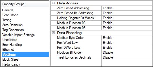
Device Propert ies — Set t ings
Data Access
Zero-Based Addressing: If the address-numbering convention for the device starts at one as opposed to
zero, the value can be specified when defining the device parameters. By default, user-entered addresses
have one subtracted when frames are constructed to communicate with a Modbus device. If the device does
not follow this convention, choose disable. The default behavior follows the convention of Modicon PLCs.
Zero-Based Bit Addressing: Within registers, memory types that allow bits within Words can be referenced
as Booleans. The addressing notation is ., where represents the bit number within the
Word. This option provides two ways of addressing a bit within a given Word; zero- or one-based. Zero-based
means that the first bit begins at 0 (range=0-15); one-based means that the first bit begins at 1 (range=1-
16).
Holding Register Bit Writes: When writing to a bit location within a holding register, the driver should only
modify the bit of interest. Some devices support a special command to manipulate a single bit within a
register (function code hex 0x16 or decimal 22). If the device does not support this feature, the driver must
perform a Read / Modify / Write operation to ensure that only the single bit is changed. When enabled, the
driver uses function code 0x16, regardless of this setting for single register writes. When disabled, the driver
uses function code 0x06 or 0x10, depending on the selection for Modbus Function 06 for single register
writes. The default is disabled.
N ote: When Modbus byte order is disabled, the byte order of the masks sent in the command is Intel byte
order.
Modbus Function 06: This driver supports Modbus protocol functions to write holding register data to the
target device. In most cases, the driver switches between functions 06 and 16 based on the number of
registers being written. When writing a single 16-bit register, the driver generally uses Modbus function 06.
When writing a 32-bit value into two registers, the driver uses Modbus function 16. For the standard Modicon
PLC, the use of either of these functions is not a problem. There are, however, a large number of third-party
devices using the Modbus protocol and many support only Modbus function 16 to write to holding registers.
This selection is enabled by default, allowing the driver to switch between 06 and 16 as needed. If a device
requires all writes to use only Modbus function 16, disable this selection.
N ote: For bit within word writes, the Holding Register Bit Mask property takes precedence over this option.
If Holding Register Bit Mask is enabled, function code 0x16 is used regardless of this property. If not enabled,
either function code 0x06 or 0x10 is used for bit within word writes.
www. ptc.com23 M od b u s Eth ern et Driver
Modbus Function 05: This driver supports Modbus protocol functions to write output coil data to the target
device. In most cases, the driver switches between these two functions based on the number of coils being
written. When writing a single coil, the driver uses Modbus function 05. When writing an array of coils, the
driver uses Modbus function 15. For the standard Modicon PLC, the use of these functions is not a problem.
There are, however, many third-party devices that use the Modbus protocol and many only support the use
of Modbus function 15 to write to output coils regardless of the number of coils. This selection is enabled by
default, allowing the driver to switch between 05 and 15 as needed. If a device requires all writes to use only
Modbus function 15, disable this selection.
CEG Extension: The Modbus driver can communicate with CEG devices that support extended block sizes or
Modbus devices configured with the CEG model. This property is only available for the CEG model. The
default is enabled, indicating the device is a CEG device with extended block sizes. Disabled indicates the
device does not support the extended block sizes.
N ote: This property can be modified when an active client connection exists. In this situation, disabling the
option causes the block size ranges to change. If any of the block size properties exceed the maximum
value, they are automatically adjusted to the new maximum value.
Mailbox Client Privileges: The Modbus driver can communicate with Mailbox clients with the following
options:
l Mem ory Map Read Only: Client applications can only read from a mailbox memory map.
l Mem ory Map Read-Write: Client applications can read and write to the mailbox memory map.
l Device Write-Mem ory Map Read: Client applications can only write to a device; reads are from the
memory map.
Data Encoding
Modbus Byte Order: sets the data encoding of each register / 16-bit value. The byte order for can be
changed from the default Modbus byte ordering to Intel byte ordering using this selection. The default is
enabled, which is the normal setting for Modbus-compatible devices. If the device uses Intel byte ordering,
disable this property to read Intel-formatted data.
First Word Low: sets the data encoding of 32-bit values and the double word of 64-bit values. Two con-
secutive registers' addresses in a Modbus device are used for 32-bit data types. The driver can read the first
word as the low or the high word of the 32-bit value based on this option. The default is enabled, first word
low, to follow the convention of the Modicon Modsoft programming software.
First DWord Low: sets the data encoding of 64-bit values. Four consecutive registers' addresses in a Mod-
bus device are used for 64-bit data types. The driver can read the first DWord as the low or the high DWord
of the 64-bit value. The default is enabled, first DWord low, to follow the default convention of 32-bit data
types.
Modicon Bit Order: when enabled, the driver reverses the bit order on reads and writes to registers to fol-
low the convention of the Modicon Modsoft programming software. For example, a write to address
40001.0/1 affects bit 15/16 in the device when this option is enabled. This option is disabled (disabled) by
default.
For the following example, the 1st through 16th bit signifies either 0-15 bits or 1-16 bits, depending on the
driver using zero-based or one-based bit addressing within registers.
MSB = Most Significant Bit
www. ptc.comModbus Ethernet Driver 24
LSB = Least Significant Bit
Modicon Bit Order Enabled
M SB LSB
1 2 3 4 5 6 7 8 9 10 11 12 13 14 15 16
Modicon Bit Order Disabled
M SB LSB
16 15 14 13 12 11 10 9 8 7 6 5 4 3 2 1
Treat Longs as Decim als: when enabled, the driver encodes and decodes double-precision unsigned Long
and DWord data types as values that range from 0 to 99999999. This format specifies that each word rep-
resents a value between 0 and 9999. Values read above the specified range are not clamped, but the beha-
vior is undefined. All read values are decoded using the formula [Read Value] = HighWord * 10000 +
LowWord. Written values greater than 99999999 are clamped to the maximum value. All written values are
encoded using the formula Raw Data = [Written Value]/10000 + [Written Value] % 10000.
Tips on Settings
Dat a Types M odbus Byt e Order First Word Low First DWord Low
Word, Short, BCD Applicable N/A N/A
Float, DWord, Long, LBCD Applicable Applicable N/A
Double Applicable Applicable Applicable
If needed, use the following information and the device's documentation to determine the correct settings of
the data encoding options.
The default settings are acceptable for the majority of Modbus devices.
Dat a Encoding
Dat a Encoding
Opt ion
Modbus Byte High Byte (15..8) Low Byte (7..0)
Order
Modbus Byte
Low Byte (7..0) High Byte (15..8)
Order
High Word (31..16) Low Word (15..0)
First Word Low High Word (63..48) of Double Word in Low Word (47..32) of Double Word in 64-
64-bit data types bit data types
Low Word (15..0) High Word (31..16)
First Word Low Low Word (47..32) of Double Word in 64- High Word (63..48) of Double Word in
bit data types 64-bit data types
First DWord Low High Double Word (63..32) Low Double Word (31..0)
First DWord Low Low Double Word (31..0) High Double Word (63..32)
www. ptc.com25 M od b u s Eth ern et Driver
Device Propert ies — Block Sizes
Coils
Output Coils: Specifies the output block size in bits. Coils can be read from 8 to 2000 points (bits) at a time.
The default is 32.
Input Coils: Specifies the input block size in bits. Coils can be read from 8 to 2000 points (bits) at a time. The
default is 32.
Registers
Internal Registers: Specifies the internal register block size in bits. From 1 to 120 standard 16-bit Modbus
registers can be read at a time. The default is 32.
Holding Registers: Specifies the holding register block size in bits. From 1 to 120 standard 16-bit Modbus
registers can be read at a time. The default is 32.
Blocks
Block Read Strings: Enables group / block reads of string tags, which are normally read individually. String
tags are grouped together depending on the selected block size. Block reads can only be performed for Mod-
bus model string tags.
N otes:
1. The Instromet, Roxar, and Fluenta models (which support 32-bit and 64-bit registers) require special
consideration. The Modbus protocol constrains the block size to be no larger than 256 bytes. This
translates to a maximum of block size of 64 32-bit registers or 32 64-bit registers for these models.
2. The CEG model supports coil block sizes between 8 and 8000 in multiples of 8 and register block
sizes between 1 and 500. This model must only be used with CEG devices.
3. A bad address in block error can occur if the register block sizes are set above 120 and a 32- or 64-
bit data type is used for any tag. To prevent this, decrease the block size value to 120.
www. ptc.comYou can also read