Endo-Model Knee System - with Segmental Bone Replacement Components and MIRETO Instrument Set Surgical Technique - Waldemar Link
←
→
Page content transcription
If your browser does not render page correctly, please read the page content below
Endo-Model Knee System
with Segmental Bone Replacement Components
and MIRETO Instrument Set

                                 Surgical Technique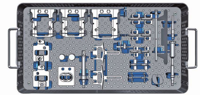
Explanation of Pictograms
         Manufacturer        Article number
                             Caution: Federal law restricts this device to sale by or on the order
         Material (number)
                             of a physician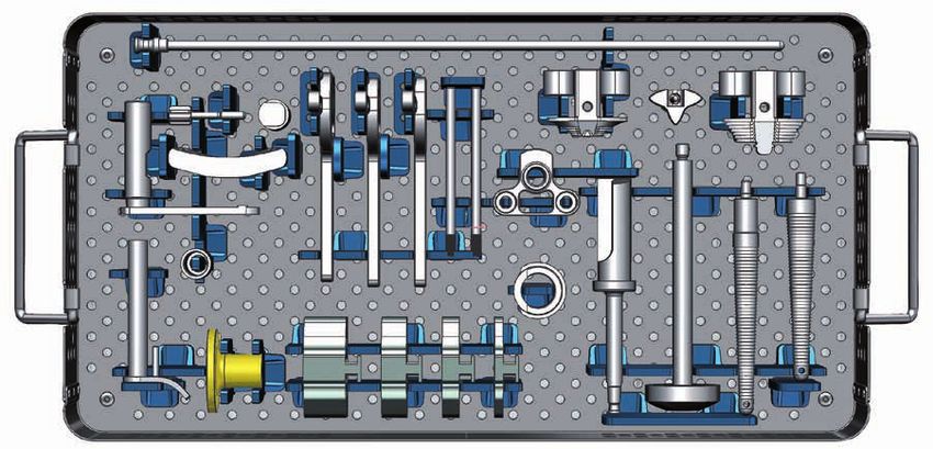
Contents

Endo-Model Knee System
with Segmental Bone Replacement Components and MIRETO Instrument Set
       System Description
02     Endo-Model Knee Prosthesis System
03     LINK PorEx Surface Modification
06     Endo-Model Modular Rotating Hinge Knee Prosthesis, Assembly: Modular Stems
07     Endo-Model Non-Rotating Hinge Knee Prosthesis
08     Indications / Contraindications
09     MIRETO Instrument Set
       Implants
10     Endo-Model Rotating Hinge Knee Prosthesis – with anti-luxation device
11     Endo-Model Rotating Hinge Knee Prosthesis – with anti-luxation device and LINK PorEx
12     Endo-Model Non-Rotating Hinge Knee Prosthesis – with hinge axis
       Endo-Model Modular Knee Prosthesis System
13     • Measurements: Joint Components
14     • Joint Components for Rotating Hinge Version – CoCrMo
15     • Joint Components for Rotating Hinge Version – CoCrMo/LINK PorEx
16     • Joint Components for Non-Rotating Hinge Version – CoCrMo
      Endo-Model Modular Joint Components
17    • Condylar Replacement
18    • Intracondylar Version
19    Modular Stems, cemented
20    Modular Stems, cementless, conical
21    Modular Stems, cementless, cylindrical
22    Femoral Segments Tilastan for Modular Rotating and Non-Rotating Hinge Knee Version
23    Femoral Segments UHMWPE for Rotational and Hinged Version Endo-Model
      Proximal Tibial Spacers and Segments for Modular Rotating and Non-Rotating Hinge Knee Version
24+25 – UHMWPE
26+27 – Tilastan
      Endo-Model Proximal Tibial Spacers for Modular Rotating and Non-Rotating Hinge Version Endo-Model
28    – UHMWPE
29+30 – Tilastan
31    Centralizers, Patellar Components
32    Replacement Sets for Endo-Model Rotating Hinge and Non-Rotating Hinge Knee Prostheses
33    MIRETO Instrument Set for Endo-Model Knee Prosthesis Systems, case 1 – 7
34    Case 1 – General Instruments
35    Case 2 – Femoral Instruments (2 trays)
37    Case 3 – Tibial Instruments
38    Case 4 – Tapered Reamers, conical & cylindrical
39    Case 5 – Trial Prostheses (2 trays)
41    Case 6 – Trial Prostheses, cylindrical
42    Case 7 – Tapered Reamers, conical
43    Additional Instrument Set for Endo-Model Rotating Hinge and Modular Knee Prostheses
        MIRETO Surgical Technique
44     Tibial Preparation
45     Tibial Resection
53     Femoral Preparation
65     Trial Reduction
67     Implantation
70     Literature
		     Important Information

                                                                                                          01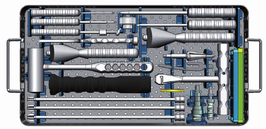
System Description

     Endo-Model Knee Prosthesis Systems

     Adherence to the low-friction principle means that       of the knee prosthesis offer a good overview of the
     the physiological range of motion of this prosthesis     operating field. The femoral and tibial components
     is optimally designed thanks to a mounted pivot with-    are simply pushed together and the UHMWPE
     in the physiological area. The Endo-Model Rotating       tibial plateau is positioned using a special instru-
     Hinge Knee Prosthesis enables flexion of the joint       ment. Both components are linked by the plateau
     up to 142°. The joint kinematics also comprise           so as to prevent luxation and without reducing
     physiological rotation which, given the special shape    the motional and rotational sequences. The Non-
     of the tibial contact surface, ensure elastic force      Rotating Hinge Knee Prosthesis is linked by the
     transmission. The hinge knee prosthesis only per-        axis mechanism.
     mits flexion of the joint up to 142° without rotation.
                                                              Flexion and rotational movement of the rotating
     With every step, and especially in the case of falls,    hinge knee prosthesis is achieved by means of a
     torsional stresses are transmitted to the prosthesis     cross joint. Hyperextension amounts to 2°. The
     anchorage which impact negatively upon the life-         compromise axis lies in the region of the physi-
     span of the anchorage in the long term. Construc-        ological pivot point. Flexion up to 142° is possible.
     tively generated, elastic force transmission ensures     With arthroplasty knee replacement, advancement
     preservation at the prosthesis/bone cement and           of the patella or of the patellar bearing surface is
     bone cement/bone interfaces. Because of the fa-          often seen. By moving the femoral component
     vorable dimensions of the Endo-Model Rotating            posteriorly relative to the tibial axis, physiological
     Hinge Knee Prosthesis, only minimal resection of         movement is also retained for the femoropatellar
     14 mm is necessary on the tibia-femur joint plane.       joint. This protects against progression of retro-
     The medium-sized intracondylar component is              patellar arthrosis. Rotation of the prosthesis ends
     only 30 mm wide. As a rule, there is thus less           in extension by form closure, which ensures a secure
     resection than with a total knee prosthesis. This is     standing position. Rotation increases continuously
     a key, positive factor with respect to subsequent        with greater flexion. This rotation is limited primarily
     revision surgery. The ideal design and dimensions        by the capsular ligament apparatus. The shape of

02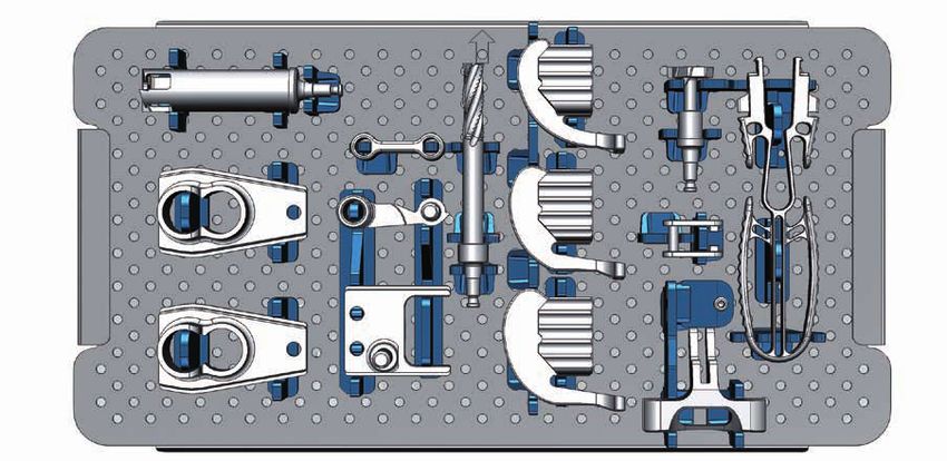
Implants

the surfaces which are in contact with each other                        The modular prosthesis stems are available for
means that further rotation is cushioned elastically                     the Endo-Model Modular Rotating Hinge Knee
by the body weight’s bearing down on the joint.                          Prosthesis both as a cemented version, without
The femoral component of the Endo-Model Rotating                         structuring, and with longitudinal structuring for
Hinge Knee Prosthesis has a physiological valgus                         cementless implantation. To achieve a central
angle of 6°.                                                             position within the medullary cavity, the tips of the
                                                                         cemented stems are fitted with star shaped
Both prosthesis components are broadly supported                         UHMWPE caps. Direct contact of the metal stems
on their corresponding joint surfaces, such that the                     with the inner wall of the bone is thereby prevented.
compressive strength of the cancellous bone vis-à-vis                    The stems are supplied in lengths of 50 mm up to
the femur and tibia is not exceeded. The runner-                         280 mm. Special femoral and tibial segments and
inspired form of the femoral component is based on                       spacers made of UHMWPE and Tilastan are avail-
the anatomical conditions. The ventral depression                        able for revision surgery of total knee prostheses, to
provides a smooth transition to the bony patellar                        reconstruct condyles and the joint line as well as for
bearing surface.                                                         tumor cases (resections). It must be noted here that
                                                                         these segments may only be used in combination
                                                                         with corresponding longer stems.

LINK PorEx Surface Modification

LINK PorEx (TiNbN = Titanium Niobium Nitride)
Surface Modification
The LINK PorEx surface modification results in a
ceramic-like surface, which significantly reduces
 chrome and nickel ions release. 1

Thanks to its outstanding hardness, abrasion prop-
erties similar to ceramics and larger wetting angle,
in contact with liquids the LINK PorEx surface
against UHMWPE has a lower coefficient of
friction compared to CoCrMo surfaces. 1

1
    Internal technical report: Study of the influence of TiNbN-coating
    on the ion release of CoCrMo-alloys in SBF buffer simulator
    testing

                                                                                                                                  03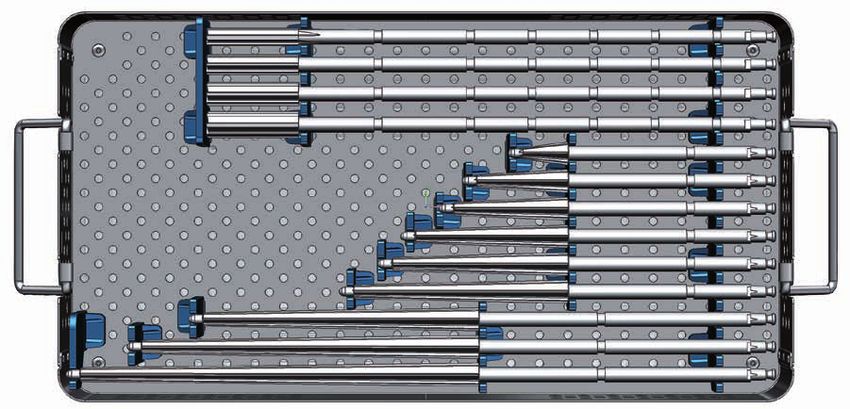
System Description

     Endo-Model Knee Prosthesis Systems

     Adherence to the low-friction principle means that the
     physiological range of movement of the rotational knee
     prosthesis is optimally designed thanks to a mounted
     pivot within the physiological area. Flexion and rotational
     movement of the rotating hinge knee prosthesis is
     achieved by means of a cross joint.

                                                                                         14 mm

                             Crosspiece

                                Guide
                                pin
                                  Tibial
                                  plateau

                                                                      6° valgus angle

           The extent of free rotation as a function of flexion
           and the constructively generated smoothly slowed
           down rotation area are shown as the hatched
           area.

           Engelbrecht, E.: Die Rotationsendoprothese des
           Kniegelenks (Rotation prosthesis for the knee
           joint), Springer-Verlag 1984, ISBN: 978-3-642-
           69819-4 (print), 978-3-642-69818-7 (online)

                                                                   Right                Left

04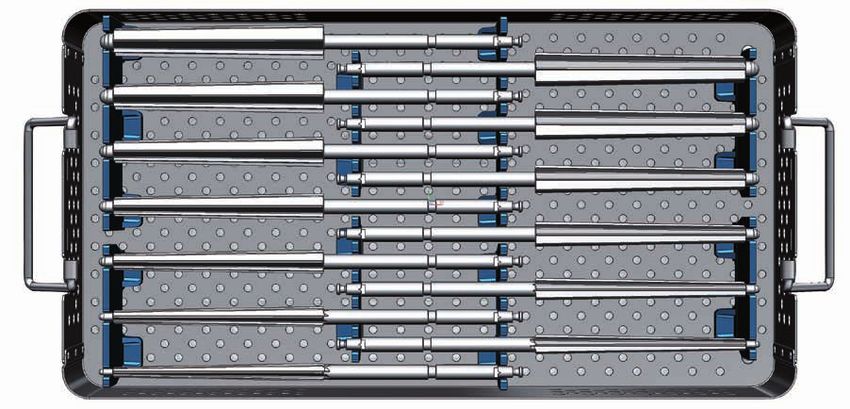
System Description

Endo-Model Knee Prosthesis Systems
Assembly: Plateau with anti-luxation device

                                                                                                   Trial screw

                                                    After cementation of tibial and femoral com-
                                                    ponents, the UHMWPE plateau is removed
                                                    from the tibial tray by loosening the trial
                                                    screw. With the knee in flexion, the upper
                                                    and lower components are assembled.

                The tibial plateau is attached to the inserter and slid
                 between the femoral and tibial components into the
             joint so that the plateau chamber grips over the flange.
                It must be ensured that the dovetail-shaped incision
               (fig. A) on the bottom of the UHMWPE plateau locks
              into the peripheral groove on the metal tibial support.

                                                                                     A

                                                      The UHMWPE plateau is
                                                      pressed down and fixed
                                                      into place by the self-
                                                      locking fixation screw.

            Self-locking fixation screw

 UHMWPE plateau                  Fixation screw

                                                                                   Implanted
                                                                          Endo-Model Modular
                    Thread

                                                                             Knee Prosthesis.
                                          Thread

Metal tibial tray

                                                                                                                 05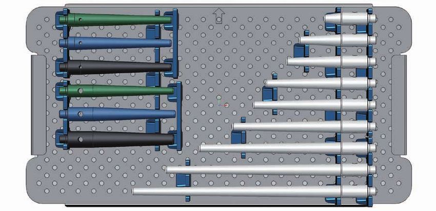
System Description

     Endo-Model Modular Rotating Hinge Knee Prosthesis
     Assembly: Modular Stems
                                    The modular stems are joined by a cone assembly. To ensure rotational stability,
                                    the stem has two opposing flanges which are inserted in the medial and lateral
                                    grooves on the femoral / tibial components.

                                    The current version features a 6 mm groove for attachment of modular stems
                                    with female taper and flanges of 3 mm or 6 mm. When attaching modular stems
                                    with 3 mm flanges, the stem must be orientated on the taper so that the threa-
                                    ded hole for the counter screw is not obscured (A). To this end, the alignment
                                    aid (15-6096/00) for modular stems is used (B). Modular stems with 6 mm
                                    flanges cannot be combined with Endo-Model implants with 3 mm grooves.

                                                                   A                                B

            The cone-shaped tip of the locking
        screw (2) in the taper (3) of the tibial or
          femoral component pushes the stem                                         Counter Screw
       firmly against the taper as it is screwed               2
         further in (1). A counter screw (4) pre-
       vents the locking screw from becoming                   3
     loose. The screw is secured from medial.

                                            2
                                                                       4

                                             3                     1

06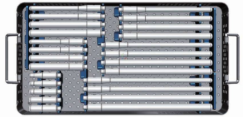
System Description

Endo-Model Non-Rotating Hinge Knee Prosthesis

The external shape, dimensions and sizes of the Endo-Model Non-Rotating Hinge
Knee Prosthesis correspond to those of the Endo-Model Rotating Hinge Knee
Prosthesis. As the implant beds required for the Non-Rotating and Rotating Hinge
versions are identical, the decision as to whether to use a Rotating Hinge or a more
stabilizing Non-Rotating Hinge Knee Prosthesis can be made intraoperatively.

The connecting piece A which is securely attached to the Non-Rotating Hinge Knee
tibial component and links it to the femoral component is drilled through to accommodate
the joint axis B. The ventral drilled hole C is provided for the grub screw D whose tip fits
into the recess E on the axis and locks the latter once the upper and lower components
have been joined.

From inside the intracondylar box of the femoral component, polyethylene bearings F
for the prosthesis axis are pushed into medial and lateral boreholes. The upper and
lower prosthesis components are joined by introducing the tibial connecting
piece into the intracondylar box of the femoral component, such that the                    A   C
                                                                             B
prosthesis axis can be inserted (always from the medial) using the threaded
rod. Articulation takes place between the prosthesis axis and the two
bearings.
                                                                            E
                                                                                D
                                                                                        F

The Endo-Model Non-Rotating Hinge Knee Prosthesis is delivered ready
assembled in a sterile condition without centering stars. To disassemble, the
grub screw D is turned counterclockwise. The threaded rod is screwed onto
the prosthesis axis B which is then pulled out. The bearings F of the upper
prosthesis component are pushed inward and removed (when the bearings are
subsequently refitted, it must be ensured that the open bearing is positioned
medially!).

The package contains two sterile trial bearings (not autoclavable). These are
inserted into the upper prosthesis component during surgery; after the trial run,
they are exchanged for the definitive bearings. These too can be exchanged
if necessary in a second intervention.

                                                                                                    07
Indications/Contraindications

      Specified Indications and Contraindications for

                                                                                                                                         Implant components
      Endo-Model Rotational and Hinged Knee Prostheses

                                                                                                                                         with TiNbN surface
                                                                                                   Rotational version

                                                                                                                        Hinged version

                                                                                                                                         modification
                                                                                  Product
     General Indications
     • Severe joint diseases with limitation of mobility due to degenerative,
       rheumatoid or post-traumatic arthrosis or arthritis. Joint fractures which                    X                     X                    X
       disallow an osteosynthetic reconstruction.

     Indications
     • Bone necroses                                                                                 X                     X                    X

     • Bicondylar arthrosis by partly damaged collateral ligaments                                     X                    –                  X*

     • Bicondylar arthrosis by completely damaged ligaments and muscular
       instability
                                                                                                      –                     X                  X*

     • Revision after primary total knee replacement                                                   X                    X                   X

     • Revision surgery after hinge knee or rotational knee joint                                      X                    X                   X

     • Revision surgery by insufficient / inadequate bone mass                                         X                    X                   X

     Differential Indications
     • Arthrosis of patella flange                                                                     X                    X                   X

     • Valgus/Varus deformities
System Description
MIRETO Instrument-Set
The new MIRETO Instrument Set allows users to perform implantation of the Endo-Model
knee prosthesis system in a safe, bone-conserving, reproducible and precise manner.
Advantages:
All intracondylar Endo-Model standard and modular implants for primary and revision indications
can be implanted using the MIRETO Instrument Set.
• Minimal number of instrument trays combined with enhanced application modularity.
• Low investment and preparation costs.
MIRETO Instruments were developed with a firm focus on ensuring optimal handling:
from storage configuration through to hygienic preparation.
• Accelerated surgical sequence.
• Shorter learning curve.
• Simple hygienic preparation.
The MIRETO Instrument Set is characterized by its simple handling, quick and
easy assembly/disassembly as well as completely guided instrumentation.
• Reproducible, reliable and precise bone resection by the user.
09Implants
Rotating Hinge Knee Prosthesis Endo-Model, with anti-luxation device
with patella flange (R)
EndoDur (CoCrMo) Radius*
15-8020/11 x-small/right 17 mm
15-8020/12 x-small/left 17 mm
15-8022/11 small/right 20 mm
15-8022/12 small/left 20 mm
15-8024/11 medium/right 23 mm
R
15-8024/12 medium/left 23 mm
15-8030/11 large/right 25 mm
15-8030/12 large/left 25 mm
* (R) Radius in the sagittal plane: Measured from the center of axis.
55
Notice:
x-small Length specification incl. centralizers *
60
small
160
65
x-small
medium
182
75
small
large
185
medium
28 x-small
190
30 small + medium large
34 large
6° Valgus Positioning
14
14
120
x-small
160
small
medium
large
right left
* Centralizers are not included in prosthesis packing
10Implants
Rotating Hinge Knee Prosthesis Endo-Model, with anti-luxation device
and LINK PorEx* surface modification
with patella flange (R)
EndoDur (CoCrMo)/LINK PorEx * Radius**
15-9020/11 x-small/right 17 mm
15-9020/12 x-small/left 17 mm
15-9022/11 small/right 20 mm
15-9022/12 small/left 20 mm
15-9024/11 medium/right 23 mm
15-9024/12 medium/left 23 mm
15-9030/11 large/right 25 mm
15-9030/12 large/left 25 mm R
** (R) Radius in the sagittal plane: Measured from the center of axis.
Same dimensions as models with anti-luxation device,
see pages 10 and 11.
Replacement Set, with anti-luxation device
EndoDur – S (CoCrMo)/
LINK PorEx *, UHMWPE
15-3027/10 x-small
15-3027/11 small
15-3027/12 medium
15-3027/13 large
* LINK PorEx: TiNbN = Titanium Niobium Nitride; surface modification (gold color).
11Implants
Non-Rotating Hinge Knee Prosthesis Endo-Model, with hinge axis
with patella flange (R)
EndoDur (CoCrMo) Radius*
15-2459/11 x-small/right 17 mm
15-2459/12 x-small/left 17 mm
15-2460/11 small/right 20 mm
15-2460/12 small/left 20 mm
15-2461/11 medium/right 23 mm
15-2461/12 medium/left 23 mm
15-2462/11 large/right 25 mm
15-2462/12 large/left 25 mm
R
* (R) Radius in the sagittal plane: Measured from the center of axis.
55 Notice:
Length specification incl.
x-small centralizers *
60
small
160
65
x-small
medium
182
75
small
large
185
medium
28 x-small 190
30 small + medium
large
34 large
6° Valgus Positioning
14
120
x-small
160
small
medium
large
right left
* Centralizers are not included in prosthesis packing
12Implants
Endo-Model Modular Knee Prosthesis System,
Measurements: Joint Components
Size A B C FK X TK R
Version mm mm mm mm mm mm mm
x-small/right 55 42 28 39 50 22 17
x-small/left 55 42 28 39 50 22 17
small/right 60 45 30 42 57 22 20
small/left 60 45 30 42 57 22 20
medium/right 65 45 30 46 62 22 23
medium/left 65 45 30 46 62 22 23
large/right 75 48 35 50 65 22 25
large/left 75 48 35 50 65 22 25
13Implants
Endo-Model Modular Knee Prosthesis System,
Joint Components Rotating Hinge Version – with anti-luxation device
Joint Components – CoCrMo
EndoDur (CoCrMo), UHMWPE EndoDur (CoCrMo), UHMWPE
Modular Joint Component Units
consisting of: Femoral Components: Tibial Components:
Width
Size Version mm Version Version
15-2815/11 x-small right 55 15-2810/11 right
15-2814/01 neutral
15-2815/12 x-small left 55 15-2810/12 left
15-2816/11 small right 60 15-2811/11 right
15-2814/02 neutral
15-2816/12 small left 60 15-2811/12 left
15-2817/11 medium right 65 15-2812/11 right
15-2814/03 neutral
15-2817/12 medium left 65 15-2812/12 left
15-2818/11 large right 75 15-2813/11 right
15-2814/04 neutral
15-2818/12 large left 75 15-2813/12 left
Screws to secure the taper assembly between joint component and stem:
A pointed stem locking screw is already located inside the taper of each joint component. The inside
packing unit of each joint component includes a counter screw (+ replacement screw) to secure the
stem locking screw.
14Implants
Endo-Model – M Modular Knee Prosthesis System,
Joint Components Rotational Version – with anti-luxation device
Joint Components – CoCrMo/LINK PorEx *
EndoDur (CoCrMo)/LINK PorEx *, UHMWPE
Modular Joint Component Units
Width
Size Version mm
15-3815/11 x-small right 55
15-3815/12 x-small left 55
15-3816/11 small right 60
15-3816/12 small left 60
15-3817/11 medium right 65
15-3817/12 medium left 65
15-3818/11 large right 75
15-3818/12 large left 75
* LINK PorEx: TiNbN = Titanium Niobium Nitride
Screws to secure the taper assembly between joint component and stem:
A pointed stem locking screw is already located inside the taper of each joint
component. The inside packing unit of each joint component includes a counter
screw (+ replacement screw) to secure the stem locking screw.
15Implants
Endo-Model Modular Knee Prosthesis System,
Joint Components Non-Rotating Hinge Version
Joint Components – CoCrMo
EndoDur (CoCrMo), UHMWPE EndoDur (CoCrMo), UHMWPE
Modular Joint Component Units
consisting of: Femoral Components: Tibial Components:
Width
Size Version mm Version Version
15-2835/11 x-small right 55 15-2830/11 right
15-2834/01 neutral
15-2835/12 x-small left 55 15-2830/12 left
15-2836/11 small right 60 15-2831/11 right
15-2834/02 neutral
15-2836/12 small left 60 15-2831/12 left
15-2837/11 medium right 65 15-2832/11 right
15-2834/03 neutral
15-2837/12 medium left 65 15-2832/12 left
15-2838/11 large right 75 15-2833/11 right
15-2834/04 neutral
15-2838/12 large left 75 15-2833/12 left
Screws to secure the taper assembly between Joint Component and Stem:
A pointed stem locking screw is already located inside the taper of each joint component.
The inside packing unit of each joint component includes a counter screw (+ replacement screw)
to secure the stem locking screw.
16Implants
Endo-Model Modular Joint Components
Condylar Replacement
EndoDur (CoCrMo), UHMWPE
Modular Joint Component Units Femoral Components, Tibial Components:
consisting of: Material: CoCrMo, UHMWPE
condylar replacement:
Unit consisting of: Size Side Width Width
15-8521/05 small right 15-8521/06 60 mm
15-2814/02 60 mm
15-8521/07 small left 15-8521/08 60 mm
15-8521/09 medium right 15-8521/10 65 mm
15-2814/03 65 mm
15-8521/11 medium left 15-8521/12 65 mm
15-8521/13 large right 15-8521/14 75 mm
15-2814/04 75 mm
15-8521/15 large left 15-8521/16 75 mm
The femoral components with female taper are not
compatible with the femoral segments size 1 to 4!
The joint components are
equipped with an anti-luxation
device. Femoral components
feature female tapers.
Femoral component: Width
Tibial component: Width
17Implants
Endo-Model Modular Joint Components
Intracondylar Version
EndoDur (CoCrMo), UHMWPE
Modular Joint Component Units Femoral Components, Tibial Components:
consisting of: intracondylar:
Size Side Width Width
15-8521/25 small right 15-8521/26 60 mm
15-2814/02 60 mm
15-8521/27 small left 15-8521/28 60 mm
15-8521/29 medium right 15-8521/30 65 mm
15-2814/03 65 mm
15-8521/31 medium left 15-8521/32 65 mm
15-8521/33 large right 15-8521/34 75 mm
15-2814/04 75 mm
15-8521/35 large left 15-8521/36 75 mm
The femoral components with female taper are not
compatible with the femoral segments size 1 to 4!
The joint components are
equipped with an anti-luxation
device. Femoral components
feature female tapers.
Femoral component: Width
Tibial component: Width
18Implants
Endo-Model Modular Stems, cemented
LF1 = with femoral components, x-small
LF2 = with femoral components, small
LF3 = with femoral components, medium
LF4 = with femoral components, large
Joint line
The centralizers for positioning the stem
in the middle of the medullary canal are
supplied separately (see page 29).
Modular Stems, cemented
EndoDur – S (CoCrMo), EndoDur – S (CoCrMo)/LINK PorEx *
Assembly length**
Femur
Tibia
EndoDur – S EndoDur – S
(CoCrMo) (CoCrMo)/ L LT LF1 LF2 LF3 LF4
LINK PorEx* mm mm mm mm mm mm
15-2950/01 15-3950/01 50 87 104 107 111 114
15-2950/02 15-3950/02 80 117 134 137 141 144
15-2950/03 15-3950/03 95 132 149 152 156 159
15-2950/04 15-3950/04 120 157 174 177 181 184
15-2950/05 15-3950/05 135 172 189 192 196 199
15-2950/06 15-3950/06 160 197 214 217 221 224
15-2950/07 15-3950/07 200 237 254 257 261 264
15-2950/08 15-3950/08 240 277 294 297 301 304
15-2950/09 15-3950/09 280 317 334 337 341 344
* LINK PorEx: TiNbN = Titanium Niobium Nitride; surface modification (gold color).
Available on request.
** Assembly length incl. centering star unit joint line
19Implants
Endo-Model Modular Stems, cementless
Modular Stems, cementless, conical
Tilastan – S
Assembly length**
Tibia Femur
L LT LF1 LF2 LF3 LF4
mm mm mm mm mm mm
15-2952/01 50 72 89 92 96 99
15-2952/02 80 102 119 122 126 129
15-2952/03 95 117 134 137 141 144
15-2952/04 120 142 159 162 166 169
15-2952/05 135 157 174 177 181 184
15-2952/06 160 182 199 202 206 209
15-2952/07 200 222 239 242 246 249
15-2952/08 240 262 279 282 286 289
15-2952/09 280 302 319 322 326 329
20Implants
Modular Stems, cementless, cylindrical
Tilastan – S
Assembly length**
Tibia Femur
L ØA ØK LT LF1 LF2 LF3 LF4
mm mm mm mm mm mm mm mm
15-2951/01 60 10 16 82 99 102 102 109
15-2951/02 60 12 16 82 99 102 102 109
15-2951/03 60 14 16 82 99 102 102 109
15-2951/04 60 16 16 82 99 102 102 109
15-2951/05 60 18 18 82 99 102 102 109
15-2951/06 120 12 16 142 159 162 162 169
15-2951/07 120 14 16 142 159 162 162 169
15-2951/08 120 16 16 142 159 162 162 169
15-2951/09 120 18 18 142 159 162 162 169
15-2951/10 160 12 16 182 199 202 202 209
15-2951/11 160 14 16 182 199 202 202 209
15-2951/12 160 16 16 182 199 202 202 209
15-2951/13 160 18 18 182 199 202 202 209
15-2951/14 200 12 16 222 239 242 242 249
15-2951/15 200 14 16 222 239 242 242 249
15-2951/16 200 16 16 222 239 242 242 249
15-2951/17 200 18 18 222 239 242 242 249
15-2951/18 240 12 16 262 279 282 282 289
15-2951/19 240 14 16 262 279 282 282 289
15-2951/20 240 16 16 262 279 282 282 289
15-2951/21 240 18 18 262 279 282 282 289
15-2951/22 280 12 16 302 319 322 322 329
15-2951/23 280 14 16 302 319 322 322 329
15-2951/24 280 16 16 302 319 322 322 329
15-2951/25 280 18 16 302 319 322 322 329
21Implants
Endo-Model Femoral Segments Tilastan,
for Modular Rotating and Non-Rotating Hinge Version Endo-Model
Height
Femoral Segments, for femoral components: Size 1 and 2
Tilastan – S
For Femoral Components:
Width
Size Version mm Side
Set: Size 1 (Height 20 mm) consisting of:
15-2971/98 medial
15-2971/00 x-small right 55 15-2971/99 lateral
15-2971/04 medial
15-2971/01 small right 60 15-2971/05 lateral
15-2971/06 medial
15-2971/02 medium right 65 15-2971/07 lateral
15-2971/08 medial
15-2971/03 large right 75 15-2971/09 lateral
15-2971/96 medial
15-2971/95 x-small left 55 15-2971/97 lateral
15-2971/14 medial
15-2971/10 small left 60 15-2971/15 lateral
15-2971/16 medial
15-2971/11 medium left 65 15-2971/17 lateral
15-2971/18 medial
15-2971/12 large left 75 15-2971/19 lateral
For Femoral Components:
Width
Size Version mm Side
Set: Size 2 (Height 25 mm) consisting of:
15-2972/98 medial
15-2972/00 x-small right 55 15-2972/99 lateral
15-2972/04 medial
15-2972/01 small right 60 15-2972/05 lateral
15-2972/06 medial
15-2972/02 medium right 65 15-2972/07 lateral
15-2972/08 medial
15-2972/03 large right 75 15-2972/09 lateral
15-2972/96 medial
15-2972/95 x-small left 55 15-2972/97 lateral
15-2972/14 medial
15-2972/10 small left 60 15-2972/15 lateral
15-2972/16 medial
15-2972/11 medium left 65 15-2972/17 lateral
15-2972/18 medial
15-2972/12 large left 75 15-2972/19 lateral
22Implants
Endo-Model – M Femoral Segments UHMWPE,
for Rotational and Hinged Version Endo-Model
Height
Femoral Segments, for femoral components: Size 1 and 2
UHMWPE
For Femoral Components:
Width
Size Version mm Side
Set: Size 1 (Height 20 mm) consisting of:
15-2965/02 medial
15-2965/01 x-small right 55 15-2965/03 lateral
15-2961/04 medial
15-2961/01 small right 60 15-2961/05 lateral
15-2961/06 medial
15-2961/02 medium right 65 15-2961/07 lateral
15-2961/08 medial
15-2961/03 large right 75 15-2961/09 lateral
15-2965/12 medial
15-2965/10 x-small left 55 15-2965/13 lateral
15-2961/14 medial
15-2961/10 small left 60 15-2961/15 lateral
15-2961/16 medial
15-2961/11 medium left 65 15-2961/17 lateral
15-2961/18 medial
15-2961/12 large left 75 15-2961/19 lateral
For Femoral Components:
Width
Size Version mm Side
Set: Size 2 (Height 25 mm) consisting of:
15-2966/02 medial
15-2966/01 x-small right 55 15-2966/03 lateral
15-2962/04 medial
15-2962/01 small right 60 15-2962/05 lateral
15-2962/06 medial
15-2962/02 medium right 65 15-2962/07 lateral
15-2962/08 medial
15-2962/03 large right 75 15-2962/09 lateral
15-2966/12 medial
15-2966/10 x-small left 55 15-2966/13 lateral
15-2962/14 medial
15-2962/10 small left 60 15-2962/15 lateral
15-2962/16 medial
15-2962/11 medium left 65 15-2962/17 lateral
15-2962/18 medial
15-2962/12 large left 75 15-2962/19 lateral
23Implants
Endo-Model Femoral Segments Tilastan,
for Modular Rotating and Non-Rotating Hinge Version Endo-Model
Height 50 mm
A
Femoral Segments, Size 3*
Tilastan
For Femoral Components:
A Width A
Version mm Size mm mm Version
Size 3* (Height 50 mm)
15-2973/01 right 60 small 60 60 left 15-2973/02
15-2973/03 right 65 medium 65 65 left 15-2973/04
15-2973/05 right 75 large 75 75 left 15-2973/06
* Only to be used in combination with longer stems (stem length above segments at least 180 mm).
Height 80 mm
A
Femoral Segments, Size 4*
Tilastan
For Femoral Components:
A Width A
Version mm Size mm mm Version
Size 4* (Height 80 mm)
15-2977/01 right 60 small 60 60 left 15-2977/02
15-2978/01 right 65 medium 65 65 left 15-2978/02
15-2979/01 right 75 large 75 75 left 15-2979/02
* Only to be used in combination with longer stems (stem length above segments at least 180 mm).
24Implants
Endo-Model Femoral Segments Tilastan,
for Modular Rotating and Non-Rotating Hinge Version Endo-Model
Height
Distal Femoral Segments
(only to be used in combination with size 4)
Tilastan – S
Height
for size
mm
15-2977/10 10 small
15-2977/20 20 small
15-2977/40 40 small
15-2977/60 60 small
15-2977/80 80 small
15-2978/10 10 medium
15-2978/20 20 medium
15-2978/40 40 medium
15-2978/60 60 medium
15-2978/80 80 medium
15-2979/10 10 large
15-2979/20 20 large
15-2979/40 40 large
15-2979/60 60 large
15-2979/80 80 large
25Implants
Endo-Model – M Femoral Segments UHMWPE,
for Rotational and Hinged Version Endo-Model
Height 50 mm
A
Femoral Segments, size 3*
UHMWPE
For Femoral Components:
A Width A
Version mm Size mm mm Version
Size 3* (Height 50 mm)
15-2967/01 right 55 x-small 55 55 left 15-2967/10
15-2963/01 right 60 small 60 60 left 15-2963/02
15-2963/03 right 65 medium 65 65 left 15-2963/04
15-2963/05 right 75 large 75 75 left 15-2963/06
* Only to be used in combination with longer stems (stem length above segments at least 180 mm).
Not compatible with LINK MEGASYSTEM-C – Modular Joint Components Endo-Model with female taper.
Height 80 mm
A
Femoral Segments, size 4*
UHMWPE
For Femoral Components:
A Width A
Version mm Size mm mm Version
Size 4* (Height 80 mm)
15-2964/99 right 55 x-small 55 55 left 15-2964/00
15-2964/01 right 60 small 60 60 left 15-2964/02
15-2964/03 right 65 medium 65 65 left 15-2964/04
15-2964/05 right 75 large 75 75 left 15-2964/06
* Only to be used in combination with longer stems (stem length above segments at least 180 mm).
Not compatible with LINK MEGASYSTEM-C – Modular Joint Components Endo-Model with female taper.
26Implants
Endo-Model – M Femoral Segments UHMWPE,
for Rotational and Hinged Version Endo-Model
Height
Femoral Segments
(only to be used in combination with size 4)
UHMWPE
Height
mm Size
15-2970/10 10 1
15-2970/20 20 2
27Implants
Endo-Model Proximal Tibial Spacers UHMWPE,
for Modular Rotating and Non-Rotating Hinge Version Endo-Model
Proximal Tibial Spacers - straight -
UHMWPE
Height
Size Size mm
Set: consisting of:
15-2516/55 x-small 5 * Important Information:
15-2516/70 x-small 15-2516/60 x-small 10 Proximal tibial spacers
15-2516/65 x-small 15
– straight – must not be
15-2516/05 small 5 combined with each other!
15-2516/29 small 15-2516/10 small 10
15-2516/15 small 15
15-2517/05 medium 5
15-2517/29 medium 15-2517/10 medium 10
15-2517/15 medium 15
15-2519/05 large 5
15-2519/29 large 15-2519/10 large 10
15-2519/15 large 15
Proximal Tibial Spacers - anatomical -
UHMWPE A
A B
Width Width
Size mm mm
Height
15-2516/24 x-small 55 40 5 mm
10 mm
15-2516/25 small 60 40
10 mm
15-2517/26 medium 65 45
15-2519/27 large 75 55 B
28Implants
Endo-Model Proximal Tibial Spacers Tilastan,
for Modular Rotating and Non-Rotating Hinge Version Endo-Model
H
Proximal Tibial Spacers, full
right and left, incl. 2 hexagon socket
countersunks with flat head screw
2.5 mm, for lateral and medial application,
Tilastan – S
H
Height
Size mm
15-2615/05 x-small 5
15-2615/10 x-small 10
15-2615/15 x-small 15
15-2616/05 small 5
15-2616/10 small 10
H
15-2616/15 small 15
15-2617/05 medium 5
15-2617/10 medium 10
15-2617/15 medium 15 Proximal Tibial Spacers, half
15-2618/05 large 5 incl. hexagon socket countersunks with
flat head screw 2.5 mm, for lateral and
15-2618/10 large 10
medial application,
15-2618/15 large 15 Tilastan – S
H
Height
Size mm
15-2990/11 x-small 5
15-2990/12 x-small 10
15-2990/13 x-small 15
15-2990/01 small 5
15-2990/04 small 10
15-2990/07 small 15
15-2990/02 medium 5
15-2990/05 medium 10
15-2990/08 medium 15
15-2990/03 large 5
Important Information:
Proximal tibial spacers of Tilastan 15-2990/06 large 10
must not be combined with each other! 15-2990/09 large 15
29Implants
Endo-Model Proximal Tibial Spacers Tilastan,
for Modular Rotating and Non-Rotating Hinge Version Endo-Model
Proximal Tibial Segments - anatomical -
Tilastan – S
B H B
Width Height
Size mm mm
15-2981/01 x-small 55 50
15-2982/01 small 60 50
15-2983/01 medium 65 50
15-2984/01 large 75 50
H
Proximal Tibial Spacers
Tilastan – S
L
Length
mm for Size
15-2981/10 10 x-small
15-2981/20 20 x-small L
15-2981/40 40 x-small
15-2981/60 60 x-small
15-2982/10 10 small
15-2982/20 20 small
15-2982/40 40 small
15-2982/60 60 small
15-2983/10 10 medium
15-2983/20 20 medium
15-2983/40 40 medium
15-2983/60 60 medium
15-2984/10 10 large
15-2984/20 20 large
15-2984/40 40 large
15-2984/60 60 large
30Implants
Centralizers,
Patellar Components
Centralizers
UHMWPE
Size
Set: consisting of:
15-2975/12 small
15-2975/01 15-2975/14 medium
15-2975/16 large
Ø 12 mm Ø 14 mm Ø 16 mm
Patellar Components
centrical, circular
UHMWPE
Ø
Size mm
15-2521/30 small 30
15-2521/35 medium 35
15-2521/40 large 40
31Implants
Replacement Sets for Rotating Hinge and Non-Rotating Hinge Version Endo-Model
Replacement Sets for Rotating Hinge Knee Replacement Sets for Rotating Hinge
Prostheses, with anti-luxation device Tibial Plateaus, with security screw
CoCrMo UHMWPE/CoCrMo/LINK PorEx*
UHMWPE/ UHMWPE/
Side Size CoCrMo LINK PorEx*
Size
15-0027/10 right/left x-small
15-0027/17 15-0037/17 x-small
15-0027/11 right/left small
15-0027/14 15-0037/14 small
15-0027/12 right/left medium
15-0027/15 15-0037/15 medium
15-0027/13 right/left large
15-0027/16 15-0037/14 large
Each package contains:
• complete coupling mechanism, * LINK PorEx: TiNbN = Titanium Niobium Nitride;
• bearing boxes, surface modification (gold color). Available on request
• PE plateau and PE plateau anchoring screw.
Each package contains:
Required: Additional Instrument Set see page 37. PE plateau and PE plateau anchoring screw.
Replacement Sets for Non-Rotating Hinge Replacement Set for Endo-Model Rotational
Knee Prostheses, with security screw Bushing
UHMWPE/CoCrMo UHMWPE/CoCrMo
Side Size Side Size
15-0027/20 right x-small 15-1027/10 right/left x-small
15-0027/21 right small 15-1027/11 right/left small
15-0027/22 right medium 15-1027/12 right/left medium
15-0027/23 right large 15-1027/13 right/left large
15-0027/30 left x-small Each package contains:
15-0027/31 left small Rotational Bushing.
15-0027/32 left medium
15-0027/33 left large
Each package contains:
PE plateau and PE plateau anchoring screw.
32Instruments
MIRETO Instrument Set for Endo-Model Knee Prosthesis Systems
The MIRETO Instrument Set comprises seven instrument trays. It was developed with the focus
on the following objectives:
Instruments are securely held in their respective positions in the tray
Ergonomic arrangement means the instruments are easy to remove, ensuring that surgery
proceeds smoothly
Optimally organized individual trays facilitate the job of the instrument nurse during the surgical procedure
Trays are clearly marked with a picture of each instrument to ensure they can be quickly equipped with
the correct instruments
On request, pictorial templates for equipping the instrument trays can be supplied.
Cleaning instructions for all take-apart instruments are also available.
MIRETO Instrument Set for Endo-Model Knee Joint Prostheses
15-6011/00 Case 1 – General Instruments
15-6012/00 Case 2 – Femoral Instruments (2 trays)
15-6013/00 Case 3 – Tibial Instruments
15-6014/00 Case 4 – Tapered Reamers conical & cylindrical
15-6015/00 Case 5 – Trial Prostheses (2 trays)
15-6016/00 Case 6 – Trial Prostheses cylindrical
15-6017/00 Case 7 – Tapered Reamers conical
33Instruments
15-6011/00 Case 1 – General Instruments
1 2 3 4 5 6 7 8 9 10
21 20 19 18 17 16 15 14 13 12 11
1 15-6001/00 Instrument Tray, Case 1, empty, 485 x 253 x 80 mm
2 64-1181/16 Hex Screwdriver, with metal handle, hex. 2 mm
3 10-5373/01 Hex Screwdriver, with metal handle, hex. 2.5 mm
4 15-8035/02 Inserter Positioner for PE plateaus
5 317-586 Inserter/Extraction Forceps for fixation pins Ø 3 mm, 210 mm
6 15-2537 Impactor Handle, small/medium, for femoral components
7 16-0115/01 Mallet, blow-back proof, incl. Spare Part Polyethylene
8 64-8008/02 Hex Screwdriver, hex 3.5 mm
9 317-658/01 Bone Awl with trocar point, 215 mm
10 15-2537/02 Impactor Handle, large, for femoral components
317-585/65 Wire Pins, Ø 3 mm, 65 mm (4 pieces)
317-585/95 Wire Pins, Ø 3 mm, 95 mm (4 pieces)
optional
11
319-581/00 Drill Pins, Ø 3 mm, 65/80 mm (4 pieces)
319-582/00 Drill Pins, Ø 3 mm, 95/110 mm (4 pieces)
15-6096/00 Alignment Device for modular stems with female taper (1 piece)
12 15-6053/00 T-Handle, with Hudson fitting
13 16-3287/00B Adapter, for LINK power tool snap lock adapter, with Hudson fitting
Adapter, optional with fitting:
16-3283/00 Hudson female/Jacobs male
14
16-3284/00 Hudson female/AO male
16-3285/00 Hudson female/Harris male
15 317-607/50 Cutting Template
16 15-6037/00 Drill, to open the femoral and tibial canal
17 16-3203/00 Impaction Plate for reamers
18 15-6098/00 Grooved Driver Tibia
19 15-6060/00 Stylus, for centralizer Ø 12 mm
20 15-6060/01 Stylus, for centralizer Ø 14 mm
21 15-6060/02 Stylus, for centralizer Ø 16 mm
34Instruments
15-6012/00 Case 2 – Femoral Instruments (Tray 1)
1 2 3 4 5 6 7-11 12 13 14
24 23 22 21 20 19 18 17 16 15
1 15-6002/00 Instrument Tray, Case 2 (Tray 1), empty below, 485 x 253 x 80 mm
Basic Frame
2 15-6030/01 Size S
3 15-6030/02 Size M
4 15-6030/03 Size L
5 15-6111/00 Interlocking Pin for basic frame
6 15-6110/00 Interlocking Spring for basic frame
Spacer, complete, 2 pieces
7 15-6045/00 Height 2 mm
8 15-6045/01 Height 10 mm
9 15-6045/02 Height 15 mm
10 15-6045/03 Height 20 mm
11 15-6045/04 Height 25 mm
12 15-6033/00 Alignment Rod, Ø 6 mm, 150 mm
13 15-6040/01 Alignment Gauge, for sizes S/M/L
14 15-6032/00 Drill for pin holes, Ø 6 mm
15 15-6038/00 Depth Mill for taper coupling
16 15-6049/00 Stylus, anterior
17 15-6039/01 Saw Guide, for ventral rim, size M/L
18 15-6039/00 Saw Guide, for ventral rim, size XS/S
19 15-6042/00 Reamer, for box profile milling, Ø 12 mm, 74 mm
20 15-6034/00 Slide-In Module, for ventral bone rim
21 15-6046/00 Protective Cap, Ø 12 mm, 54 mm
22 15-6046/01 Protective Cap, Ø 14 mm, 54 mm
23 15-6031/00 Alignment Insert, right
24 15-6031/01 Alignment Insert, left
35Instruments
15-6012/00 Case 2 – Femoral Instruments (Tray 2)
1 2 3 4 5 6 7 8
14 13 12 11 9 10
1 15-6002/00 Instrument Tray, Case 2 (Tray 2), empty above, 485 x 253 x 80 mm
2 15-6036/00 Reamer for box pre-milling, Ø 24 mm
3 15-6042/01 Reamer for box profile milling, Ø 12 mm, 100 mm
Basic Milling Guidances for condyle milling, complete
4 15-6043/01 Size S
5 15-6043/02 Size M
6 15-6043/03 Size L
7 15-6044/02 Reamer for condyle milling, Ø 26 mm
8 15-6044/01 Inserting Forceps for condyle milling guidance
9 15-6044/00 Condyle Milling Guidance for condyle milling
10 15-6044/20 Screw for condyle milling guidance
11 15-6044/30 Lever for condyle milling guidance
12 15-6041/00 Slide-In Module for box profile milling (3 parts)
13 15-6035/00 Slide-In Module for box pre-milling Endo-W
14 15-6035/01 Slide-In Module for box pre-milling Endo-M Standard
36Instruments
15-6013/00 Case 3 – Tibial Instruments
1 2 3 6 5 4 7 8 9 10 11
22 21 20 19 18 17 16 15 14 13 12
1 15-6003/00 Instrument Tray, Case 3, empty, 485 x 253 x 80 mm
2 16-3242/00 Alignment Rod Tibia
3 15-6058/00 Tibial Saw Guide, 3 parts
Drill Templates Tibia
4 15-6050/01 Size S
5 15-6050/02 Size M
6 15-6050/03 Size L
7 16-3211/00 Guide Rod (2 pieces)
8 15-6051/00 Alignment Gauge
9 15-6054/01 Compressor, for Endo-Model – M, size XS/S
10 15-6055/02 Compressor Extension, for Endo-Model, size M/L
11 15-6054/02 Compressor, for Endo-Model – M, size M/L
12 15-6056/02 Stem Compressor, size M/L
13 15-6056/01 Stem Compressor, size S
14 16-3197/00 T-Handle
15 15-6052/00 Drill, Ø 20 mm
16 16-3271/20 Drill Guide
Spacer, Tibial Alignment, for sizes S/M/L
17 15-6059/00 Height 5 mm
18 15-6059/01 Height 10 mm
19 15-6059/02 Height 15 mm
20 15-6059/03 Height 25 mm
21 15-6062/00 Impaction Plate Tibia
22 15-6057/00 Alignment Gauge, for tibia resection (3 parts)
37Instruments
15-6014/00 Case 4 – Tapered Reamers conical & cylindrical
1 2 3 4 5
14 13 12 11 10 9 8 7 6
1 15-6004/00 Instrument Tray, Case 4, empty, 485 x 253 x 80 mm
Tapered Reamers, cylindrical, with Hudson fitting B
2 15-6048/00 Ø 12 mm
3 15-6048/01 Ø 14 mm
4 15-6048/02 Ø 16 mm
5 15-6048/03 Ø 18 mm
Tapered Reamers, conical, with Hudson fitting B
6 15-6047/01 Ø 16 mm 50 mm
7 15-6047/02 Ø 16 mm 80 mm
8 15-6047/03 Ø 16 mm 95 mm
9 15-6047/04 Ø 16 mm 120 mm
10 15-6047/05 Ø 16 mm 135 mm
11 15-6047/06 Ø 16 mm 160 mm
12 15-6047/07 Ø 16 mm 200 mm
13 15-6047/08 Ø 16 mm 240 mm
14 15-6047/09 Ø 16 mm 280 mm
38Instruments
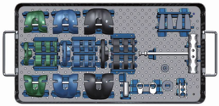
15-6015/00 Case 5 – Trial Prostheses (Tray 1)
1 2 5 3 6 4 7 11 12 13 14
37 35 33 31 29 27 25 23 21
8 38 36 34 9 32 30 28 10 26 24 22 20 19 18 17 16 15
1 15-6005/00 Instrument Tray, Case 5 (Tray 1), empty below, 485 x 253 x 80 mm
Tibia Trial Prostheses, intracondylar
2 15-6065/01 Size S
3 15-6065/02 Size M
4 15-6065/03 Size L
Femur Trial Prostheses, intracondylar
5 15-6067/01 Size S left
6 15-6067/02 Size M left
7 15-6067/03 Size L left
8 15-6068/01 Size S right
9 15-6068/02 Size M right
10 15-6068/03 Size L right
Femoral Trial Segments, universal
11 15-6088/01 Height 20 mm right
12 15-6088/02 Height 20 mm left
13 15-6093/01 Height 25 mm right
14 15-6093/02 Height 25 mm left
15 15-6061/00 Extraction Instrument for trial prostheses (2 parts)
16 15-6094/00 Trial Support Ring, height 10 mm, Ø 28 mm
17 15-6070/00 Femoral Trial Adapter, for modular stems M10/M12
18 15-6066/01 Trial Connection Component for hinged knee versions sizes S/M/L
19 15-6066/00 Trial Connection Component for rotational knee versions sizes S/M/L
20 15-6066/20 Trial Axis, for sizes S/M/L
Trial Segments Tibia
21 15-6078/03 Height 5 mm Sizes L right
22 15-6079/03 Height 5 mm Sizes L left
23 15-6080/03 Height 10 mm Sizes L right
24 15-6081/03 Height 10 mm Sizes L left
25 15-6082/03 Height 15 mm Sizes L right
26 15-6083/03 Height 15 mm Sizes L left
27 15-6078/02 Height 5 mm Size M right
28 15-6079/02 Height 5 mm Size M left
29 15-6080/02 Height 10 mm Size M right
30 15-6081/02 Height 10 mm Size M left
31 15-6082/02 Height 15 mm Size M right
32 15-6083/02 Height 15 mm Size M left
33 15-6078/01 Height 5 mm Size S right
34 15-6079/01 Height 5 mm Size S left
35 15-6080/01 Height 10 mm Size S right
36 15-6081/01 Height 10 mm Size S left
37 15-6082/01 Height 15 mm Size S right
38 15-6083/01 Height 15 mm Size S left
39Instruments
15-6015/00 Case 5 – Trial Prostheses (Tray 2)
1 2 3 4 5 6 7
16 15 14 13 12 11 10 9 8
1 15-6005/00 Instrument Tray, Case 5 (Tray 2), empty, 485 x 253 x 80 mm
Tibial Trial Stems, for Endo-Model prosthesis stems
2 15-6063/01 Size S
3 15-6063/02 Size M
4 15-6063/03 Size L
Femoral Trial Stems, for Endo-Model prosthesis stems
5 15-6064/01 Size S
6 15-6064/02 Size M
7 15-6064/03 Size L
Trial Stems, conical, for femoral and tibial components, cemented/cementless
8 15-6071/01 Length 50 mm
9 15-6071/02 Length 80 mm
10 15-6071/03 Length 95 mm
11 15-6071/04 Length 120 mm
12 15-6071/05 Length 135 mm
13 15-6071/06 Length 160 mm
14 15-6071/07 Length 200 mm
15 15-6071/08 Length 240 mm
16 15-6071/09 Length 280 mm
40Instruments
15-6016/00 Case 6 – Cylindrical Trial Stems
1 2 3 4 5 6 7 8 9 10 11 12 13 14 15 16 17
26 25 24 23 22 21 20 19 18
1 15-6006/00 Instrument Tray, Case 6, empty, 485 x 253 x 80 mm
Trial Stems, cylindrical, cementless
2 15-6073/01 Ø 12 mm Length 120 mm
3 15-6073/02 Ø 14 mm Length 120 mm
4 15-6073/03 Ø 16 mm Length 120 mm
5 15-6073/04 Ø 18 mm Length 120 mm
6 15-6074/01 Ø 12 mm Length 160 mm
7 15-6074/02 Ø 14 mm Length 160 mm
8 15-6074/03 Ø 16 mm Length 160 mm
9 15-6074/04 Ø 18 mm Length 160 mm
10 15-6075/01 Ø 12 mm Length 200 mm
11 15-6075/02 Ø 14 mm Length 200 mm
12 15-6075/03 Ø 16 mm Length 200 mm
13 15-6075/04 Ø 18 mm Length 200 mm
14 15-6076/01 Ø 12 mm Length 240 mm
15 15-6076/02 Ø 14 mm Length 240 mm
16 15-6076/03 Ø 16 mm Length 240 mm
17 15-6076/04 Ø 18 mm Length 240 mm
18 15-6077/01 Ø 12 mm Length 280 mm
19 15-6077/02 Ø 14 mm Length 280 mm
20 15-6077/03 Ø 16 mm Length 280 mm
21 15-6077/04 Ø 18 mm Length 280 mm
22 15-6072/00 Ø 10 mm Length 60 mm
23 15-6072/01 Ø 12 mm Length 60 mm
24 15-6072/02 Ø 14 mm Length 60 mm
25 15-6072/03 Ø 16 mm Length 60 mm
26 15-6072/04 Ø 18 mm Length 60 mm
41Instruments
15-6017/00 Case 7 – Conical Tapered Reamers
1 8 10 12 14 13 11 9
6 4 2 3 5 7
1 15-6007/00 Instrument Tray, Case 7, empty, 485 x 253 x 80 mm
Tapered Reamers: conical, with fitting B: Hudson
2 16-5130/12 Ø 12 mm Stem length 130 mm
3 16-5130/13 Ø 13 mm Stem length 130 mm
4 16-5130/14 Ø 14 mm Stem length 130 mm
5 16-5130/15 Ø 15 mm Stem length 130 mm
6 16-5130/16 Ø 16 mm Stem length 130 mm
7 16-5130/17 Ø 17 mm Stem length 130 mm
8 16-5130/18 Ø 18 mm Stem length 130 mm
9 16-5130/19 Ø 19 mm Stem length 130 mm
10 16-5130/20 Ø 20 mm Stem length 130 mm
11 16-5130/21 Ø 21 mm Stem length 130 mm
12 16-5130/22 Ø 22 mm Stem length 130 mm
13 16-5130/23 Ø 23 mm Stem length 130 mm
14 16-5130/24 Ø 24 mm Stem length 130 mm
42Instruments
Additional Instrument Set
for Endo-Model Rotating Hinge Knee and Endo-Model Modular Knee Prostheses
for Endo-Model Rotating Hinge Knee and Modular Knee Prostheses
15-2529/90 Set, complete, in 1 small container K1,
on 1 tray with storage racks
05-1000/01 Small Container K1, only, 460 x 190 x 92 mm
15-2529/91 Tray, empty, 405 x 165 x 50 mm
64-8008/02 Hex Screwdriver with metal handle, hex 3.5 mm, 250 mm
15-2544 Separate Rod for removal of the rotating bushing version V02, Ø M5, 210 mm
10-5373/01 Hex Screwdriver with metal handle, hex 2.5 mm, 180 mm
15-2545 Torque Wrench, hex 2.5 mm, 205 mm
43MIRETO Surgical Technique
Tibial Preparation
01
Mark the entry point and open the tibial canal with
the drill (15-6037/00) at the point of attachment of
the anterior cruciate ligament. The drill can either
be used manually with the T-handle (15-6053/00)
or driven mechanically.
02
Assemble the tapered reamer with the T-handle (15-6053/00).
The tibial stop plate (15-6062/00) is clicked into the designated
groove on the tapered reamer stem. When using cementless
modular stems: Ream with increasing diameters until the awl
has achieved contact with the cortical bone over a continuous
distance of approx. 50 mm. The implant must correspond with
the tapered reamer last used in terms of diameter and length.
In the case of cemented modular stems, the tapered reamer
should be at least 2 mm larger than the planned stem diameter.
Important information:
The position of the stop plate represents the lower edge of
the tibial metal tray. The tapered reamers must not be used
with a drive.
44MIRETO Surgical Technique
03
Once the tapered reamer is securely positioned
by means of contact with the cortical bone, the
T-handle and the stop plate are both removed.
The tapered reamer remains in the medullary
space. The tibial resection alignment instrument
(15-6057/00) is attached, in a pre-assembled state
(scale setting “0”), onto the tapered reamer. It must
be ensured here that the stylus pin, which can be
positioned medially or laterally, is guided in the
designated groove.
04
The saw guide (15-6058/00) is attached to the
alignment guide and placed on the ventral tibia.
Ideally, the saw guide is pre-assembled in such
a way that tibial resection can be performed
from medial.
45MIRETO Surgical Technique
05
By turning the setting screw on the alignment guide,
the desired resection height can be set and read
off the scale. The cutting template (317-607/50)
can be used to check the resection height. For
first-time surgery, the resection height should not
be greater than 10 mm. For revision surgery, as far
as possible very little or no bone should be addi-
tionally resected. Resection is performed without
a dorsal slope at a 90° angle to the tibial axis
(default setting due to instrument design).
06
After setting the desired resection height, the
saw guide is fixed in place using two fixation pins
(317-585/65 or /95) or drill pins (319-581/00 or
319-582/00). For this, the pins are initially inserted
into the holes on the line marked “0” in the medial
holes groups (results in parallel alignment of the
pins). After removing the tapered reamer, a third
fixation pin or drill pin is inserted at an angle in
one of the neighboring hole groups to secure
the saw guide in place.
46MIRETO Surgical Technique
07
After removing the tapered reamer, the bone can
be resected. To achieve an optimal cutting result,
saw blades with a width of 1.24 – 1.27 mm are
recommended. The fixation pin inserted at an
angle is then removed and the saw guide is
pulled off toward the front. The two parallel fixa-
tion or drill pins can remain in place. These allow
the saw guide to be reattached at the + 2 or + 4
mm level in order to repeat resection later on.
08
The tapered reamer used last is again inserted in the
medullary canal with the stop plate attached. The final
implant size is determined by applying a drill template
(15-6050/01, /02, /03) which corresponds exactly in size
with the respective implant. Since the Endo-Model implants
are also anchored by the diaphysis, full cortical bone
support of the prosthesis is not necessary. The
implant must not project over the bone margin.
The alignment guide (15-6051/00) is guided over the
stem of the tapered reamer and connected to the
cylindrical elevations of the drill template.
For revision surgery, the level of the tibial preparation
can be raised to the level of the planned and to be recon-
structed joint line. For this, spacers (15-6059/00, /01, /02,
/03) of the relevant implant heights can be pushed on the
drill template.
47MIRETO Surgical Technique
09
For rotational alignment, the alignment rod
(16-3242/00) can be pushed from ventral onto
the drill template. The ventral alignment rod must
be aligned in the area between the middle of the
tibial tuberosity and its medial margin.
10
After rotational alignment, the drill template
is fixed with four fixation pins or drill pins. Mark
the rotary alignment on the ventral cortical bone
of the tibial head.
48MIRETO Surgical Technique
11
Remove the alignment guide, alignment rod
and tapered reamer.
12
Attach the drill guide (16-3271/20) to the drill
template. The lower collar must sit flush. The
collarless area points toward dorsal.
49MIRETO Surgical Technique
13
Insert the drill (16-6052/00) into the proximal tibia
as far as it will go.
14
Screw the guide rods (16-3211/00) into the dorsal
thread holes of the drill template.
50MIRETO Surgical Technique
15
For Endo-Model – M and Endo-Model Standard
tibial components, sizes XS and S
• Screw the stem compressor (15-6056/00, /01)
onto the corresponding compressor (15-6054/01, /02).
• Attach the handle (16-3197/00).
For Endo-Model Standard tibial components,
sizes M and L
• Attach the compressor addition (15-6055/02)
onto the compressor (15-6054/02).
• Screw the stem compressor (15-6056/02)
onto the compressor and attach the handle.
16
Insert the compressor via the guide rods
as far as possible on the drill template. Finally
remove all instruments.
51MIRETO Surgical Technique
17
Assemble the tibial trial.
If necessary, push in trial washers
from medial and/or lateral.
18
Insert the trial prosthesis.
52MIRETO Surgical Technique
Femoral Preparation
01
Mark the entry point and open the femoral canal
with the drill (15-6037/00). The drill can either be
used manually with the T-handle (15-6053/00)
or driven mechanically.
02
Assemble the tapered reamer with the T-handle
(15-6053/00). The femoral stop plate (16-3203/00)
is clicked into the designated groove on the tapered
reamer stem. When using cementless modular stems:
Ream with increasing diameters until the awl has
achieved contact with the cortical bone over a con-
tinuous distance of approx. 50 mm. The implant must
correspond with the tapered reamer last used in
terms of diameter and length.
In the case of cemented modular stems, the tapered
reamer should be at least 2 mm larger than the
planned stem diameter.
Once the tapered reamer is securely positioned
by means of contact with the cortical bone, the
T-handle and the stop plate are both removed.
The tapered reamer remains in the medullary canal.
Important information:
The position of the stop plate represents the level
of the joint line. The tapered reamers must not be
used with a drive.
53MIRETO Surgical Technique
03
Assemble the base frame (15-6030/01,
/02, /03) in line with the size of the
tibial preparation:
• Insert the locking pin (15-6111/00) into
the groove on the relevant side L (left)
or R (right).
• Insert the locking spring (15-6110/00) into
the outer drill hole opposite the locking pin.
•T he alignment insert (15-6031/00, /01) is
then attached to the front of the base
frame and secured in place by closing
the locking pin.
04
Attach the base frame onto the stem of the
tapered reamer and guide the instrument on
the joint surface.
54MIRETO Surgical Technique
05
With revision surgery or extreme varus or
valgus deformities, different or same-sized
spacers (15-6045/00 to/04) can be inserted
laterally into the base frame medially, laterally
or on both sides for a more stable fixation
and distalization of the joint line.
06
Check the emergence point of the angled anterior
saw cut. Insert the alignment rod (15-6033/00) as
far as possible into the alignment insert. Position
the anterior stylus (16-6049/00) in the designated
groove in the alignment rod and push up to the
ventral bone. If the marking line of the selected
prosthesis size is around the middle of the align-
ment rod, the saw blade will emerge precisely at
the contact point of the ventral cortical bone. If the
marking is significantly below the lower third or
below the alignment rod, the position of the
tapered reamer must be corrected to ventral
and the emergence point checked again.
55MIRETO Surgical Technique
07
Check the incision for femoral segments (optional)
and the anterior and posterior saw cuts using
the cutting template (317-607/50).
08
Insert the alignment guide (15-6040/01) into the
slot of both cylindrical drill holes in the base frame
as far as possible. Check and determine the rotation/
position of the prosthesis axis with respect to the epi-
condyles. The position of the tips of the alignment
guide represents the distance of the prosthesis
axis in relationship to the position of the joint line.
56MIRETO Surgical Technique
09
Fix the base frame by inserting four fixation pins
(317-585/65 or /95) or drill pins (319-581/00 or
319-582/00) in the medial and lateral drill holes.
10
Remove the alignment insert and the tapered
reamer. Attach and secure the slide-in unit for the
ventral bone margin (15-6034/00) in the T-groove of
the base frame from above. Insert the short rea-
mer (15-6042/00) three times as far as it will go.
57MIRETO Surgical Technique
11
Pre-drill two recesses for the medial and lateral
fixation pegs for the Endo-Model – M or – W knee
prostheses using the drill for making drill holes for
pins (15-6032/00). This step is not necessary for
the Endo-Model Standard prosthesis.
12
Remove the previous insert. Attach and secure the
saw guide for the ventral margin (15-6039/00, /01)
of the same size in relation to the base frame. Make
the anterior saw cut. To achieve an optimal cutting
result, saw blades with a width of 1.24 – 1.27 mm
are recommended.
58MIRETO Surgical Technique
13
Make the posterior saw cuts through the two
medial and lateral saw slots in the base frame.
The saw guide is to remain in the base frame
so as to stop the saw blade from slipping out
of the guide and inwards.
14
Remove the saw guide. Insert and secure the slide-in
unit for box preliminary milling (15-6035/00, /01). The
choice of slide-in unit depends on the Endo-Model
prosthesis used (Standard – M or Standard – W). Insert
the reamer twice as far as it will go for preliminary
milling (15-6036/00).
59You can also read