Intramedullary Nail - Intrauma
←
→
Page content transcription
If your browser does not render page correctly, please read the page content below
Intramedullary Nail
Data and images
Intrauma S.p.A. reserves the right to make changes to the design and finish of the products shown and
described in this catalogue without prior notice.
The images are provided for information purposes only.
The information displayed is purely indicative about some general features of the products shown
herein.
This information does not constitute in any way whatsoever a description of the specific features by the
Manufacturer.
Therefore, we recommend the customer to always contact the company Intrauma S.p.A. in order to
obtain complete information on the specific features.
© The contents of this catalogue are protected by copyrights.
The reproduction of these contents is possible only if expressly authorized by Intrauma S.p.A.
It is not allowed to copy and distribute this catalogue without prior authorization.                       0 5 4 6
Intramedullary Nail
Indications
Elos 180, 240:
intended for stabilizing various types of
intertrochanteric fractures of the femur
Elos 300, 340, 360, 380, 400, 420, 440, 460:
intended for fixation of femoral fractures occurring
from the base of the femoral neck extending
distally to a point approximately 10 cm proximal
to the intercondylar notch. Fracture types include
basilar neck, intertrochanteric, subtrochanteric
fractures and femoral shaft fractures. These
femoral fractures may occur as a result of trauma,
non-union, malunion, pathological fractures, and
impending pathological fractures.

Controindications
Elos 180, 240:
low subtrochanteric, diaphyseal femur, isolated or
combined femoral neck fractures.
Elos 300, 340, 360, 380, 400, 420, 440, 460:
isolated femoral neck fracture or combined with
middle third and distal diaphyseal femur fracture.

                                                       Elos 180, 240   Elos 300, 340, 360, 380,
                                                                          400, 420, 440, 460

                                                                                                  3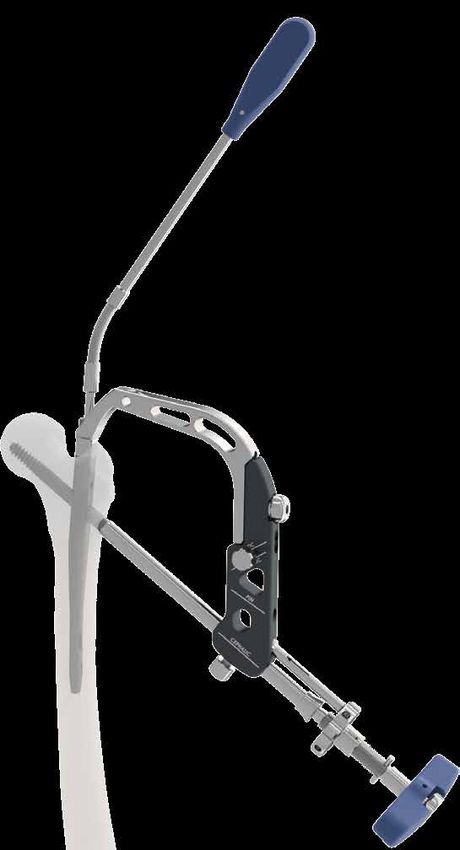
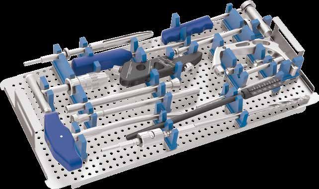
Characteristics

                                         Closure cap

                                         Cannulated grub screw
                                         pre-assembled to lock
                                         cephalic screws

            12 mm
                                            Wire hole temporary
                                            stabilisation and site for
                                            optional second screw
                      13 mm

           15 mm              CCD 127°

        Trapezoidal
          section

                                          Screw head with
                                          internal socket to
    Side wall section                     facilitate insertion
    expanded to increase                  Distal locking screw
    mechanical resistance                 Ø 5 mm, can be
    in the most critical                  inserted in static
    areas                                 or dynamic position

4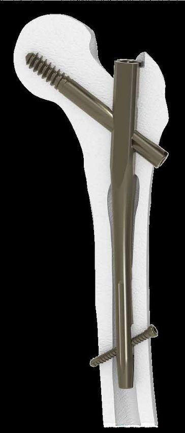
Flat side wall
                                                    to facilitate
                                                    insertion

Flared threading creates
a large surface to support
bone

                                                                Optional
                                                                anti-rotation screws

        Occupied surface compared
       to nails with traditional section

             Ø 15,5           Ø 16         Ø 16,5

176 mm²     201 mm²          214 mm²    227 mm²

              Various degrees of inclination
              in holes for the entry and exit
              of diaphysis screws, reducing
                                                       Distal cut and lengthwise
              risk of fracture
                                                       grooves to elasticize the
                                                       implant

                                                                                5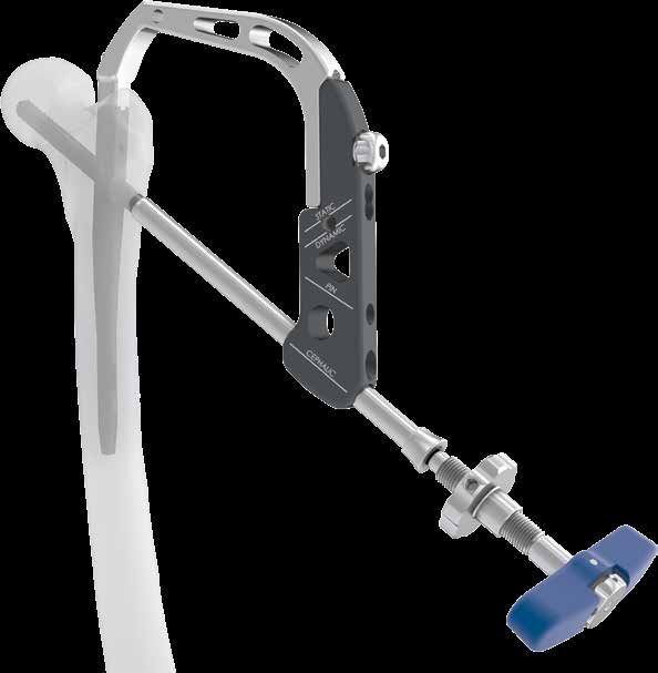
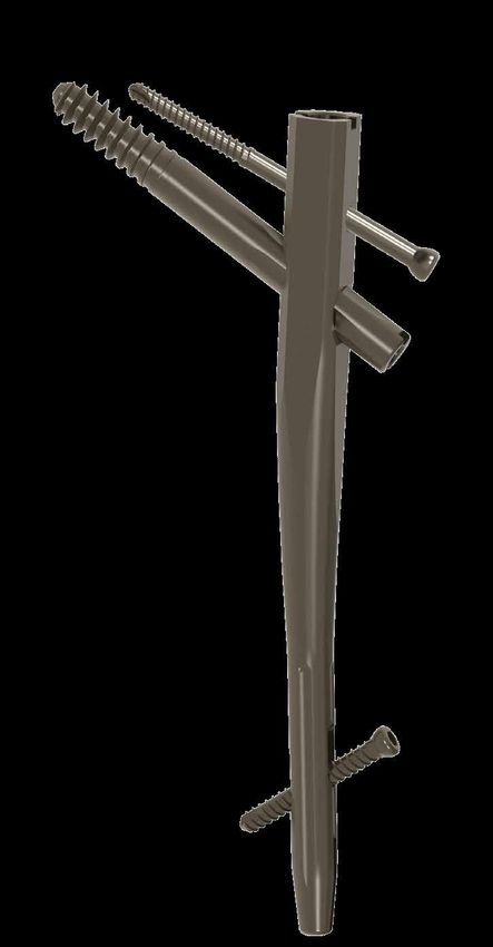
Specific implants
                             4°

                               180 mm

                                                                  240 mm

                                                                                  300, 340, 360, 380, 400, 420, 440, 460 mm
                                        Ø 10
                                        mm
        Ø 10
        mm

               Cannulated
               closure cap                                                 Ø 10
                                                                           mm
    32 mm

     Cannulated cephalic screw          Ø 10.5 mm

             Ø 5 mm
                             Distal screw

             Ø 5 mm
                                            Anti-rotation screw

6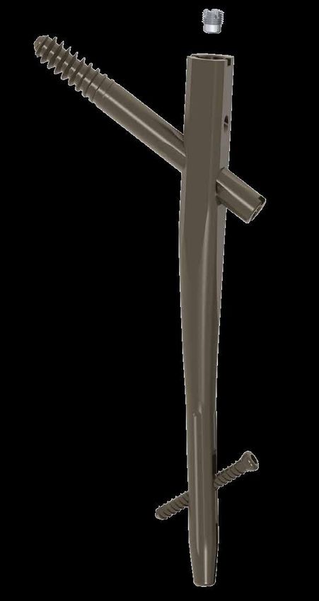
Surgical technique
Please note
This surgical technique is made available
to healthcare professionals to illustrate the
recommended procedures for using the Elos                               10°-15°
System.
It offers general guide lines that should be
followed with the awareness that the surgeon
must consider the specific needs of each patient.
The supervision of an experienced surgeon in the
use of the Elos System is recommended.

Patient positioning
The patient is placed on the fracture table, in a
supine or lateral decubitus position according to
surgeon preference and/or fracture pattern.
Reduction of the fracture is required, as
anatomically as possible; the torso may be
abducted 10°-15° to allow clear access to the
intramedullary canal. It is preferred a closed
reduction; if this is not possibile, open reduction
may be necessary.
WARNING: the correct patient positioning and
fracture reduction are essential to achieve a
successful outcome.

                                                      Entry point
                                                      The tip of the greater trochanter is located by
                                                      palpation.
                                                      A longitudinal incision is made proximal to the
                                                      greater trochanter.

                                                                                                        7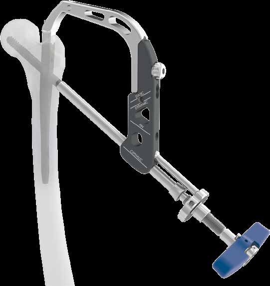
180-240-300-340-360-380-400-420-440-460
                            Surgical technique
                                 1/3   2/3

    1. Identify entrance
    point on the anterior                    2. Open the medullary
    third and posterior two-                 canal using the curved
    thirds of the greater                    cannulated trocar (SE202).
    trochanter. Position                     Use the mandrel (SE201)
    on the apex of the                       to insert the Ø 2.8 mm
    trochanter.                              guide wire.

    3. Use the paratissue
    cannula (SE203) to
    prepare the nail site
    with the trochanteric                     4. Assemble the nail on the introducer (SE206A) using
    cutter (SE204).                           the nail introducer rod (SE206B) and tighten using
    Insert up to the line.                    the assembler screwdriver (SE205).

    5. Insert the nail on
    the guide wire and
    continue until the
    correct position is                             6. Assemble the guide (SE208A) on the nail
    reached.                                        introducer (SE206A).

8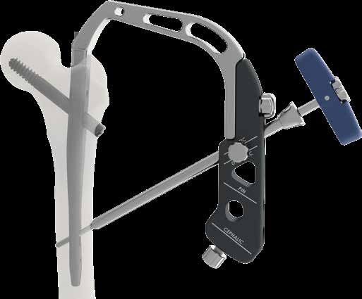
7. Assemble the cannulated trocar
                                                  (SE211) and cutter cannula (SE210) and
                                                  insert into the hole at 127° on the guide
                                                  until the lateral cortex is contacted.
                                                  Insert the Ø 3 mm threaded guide wire.

                                          10 mm

8. Use the measure (SE212) to measure the
  length of the cephalic screw on the wire.
      If the guide wire is inserted up to the
  subchondral tissue, subtract 10 mm from
                      the measured length.

                                                        9. If necessary, insert Ø 3 mm L. 350 mm
                                                        anti-rotation wire using the cannula
                                                        (SE214).

                                                                                                   9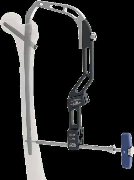
180-240-300-340-360-380-400-420-440-460
                             Surgical technique

                                                           11. Insert the
                                                           cutter on the
                                                           wire and drill up
                                                           to the line.

     10. Adjust the graduated cutter (SE213)
     using the measurement taken.

     12. Couple the cephalic screw with the
     introducer (SE215) by means of the internal tie
     rod of the instrument: manually screw up to the
     stop and then unscrew by about half a turn.

     13. Loosen the nut.
     Insert the
     cephalic screw
     on the wire until the
     correct position is
     reached.

10
14. To retrieve the fragment, insert the
compression pin (SE216) into the guide
hole. Rotate the nut until the necessary
compression is achieved.
If necessary use the compression rod
(SE235) into the holes of nut.
15. To stop rotation and slippage of
the cephalic screw, fully tighten the
locking grub screws pre-assembled on
the nail, using the Flexible Screwdriver
(SE217M). To allow slippage of the
cephalic screw, unscrew one-quarter
turn the locking grub screw pre-
assembled, keeping the introduction
sleeve in the horizontal or vertical
position in relation to the operating
table.
11180-240-300-340-360-380-400-420-440-460
Surgical technique
ANTI-ROTATION SCREW OPTION
16. Use the measure (SE225) to measure the length of the
screw on the wire. Alternatively, select a screw 15mm shorter
than the cephalic screw used.
Remove the wire.
17. Insert the protection cannula (SE218)
and the trocar (SE219) and make a hole of
3 - 4 cm with the drill bit (SE220).
18. Insert the screw using
the introducer (SE221) after
assembling it as in point 21.
12180
Surgical technique
19. Insert the cannula (SE218) and
the measuring trocar (SE219) into
the desired guide position, static or
dynamic. Insert until the diaphysis is
contacted.
To achieve the correct position,
the notch on the cannula must be
visible as in the illustration.
OK
20. Make a hole and measure using the notch on
the helical drill bit (SE220).
21. Gently tighten the diaphyseal screws
on the introducer (SE221).
22. Insert the diaphyseal screw with the introducer
(SE221), until the reference mark (A).
23. Insert the cap,
A
using a guide
wire if necessary.
Tighten with the
Set Screw/End Cap
Flexible Screwdriver
(SE217M).
13240 and 300 - Technique for insertion
of distal screws with guide
2. Insert the cannula
(SE218) and
1. Assemble the measuring
the introducer trocar (SE219) into
(SE206A) and the desired hole of
the distal guide the guide.
(SE229A).
4. Insert the
screw using
the introducer
(SE221) after
assembling it as
in point 21, and
tighten until the
reference mark
3. Drill and (A). Repeat the
measure the hole operation for
using the notch on the other hole
the helical as necessary.
drill bit (SE220).
A
5. Insert the closure cap, using a guide wire if
necessary. Tighten with the with the Set Screw/End
Cap Flexible Screwdriver (SE217M).
See point 23 page 13
14300, 340, 360, 380, 400, 420, 440, 460
Freehand technique for distal screws
1. Identify the position
of the hole to be made
and make a hole with the
helical drill bit (SE222).
Measure the length of the
screw using the graduated
sleeve (SE223).
2. Insert the diaphyseal screw
with the introducer (SE221)
after assembling it as in point
21, and tighten.
3. Insert the closure cap, using a guide wire if
necessary. Tighten with the with the Set Screw/
End Cap Flexible Screwdriver (SE217M).
See point 23 page 13
15Information for orders
Short nails Ø 10 mm - 127°
Ref. L Ref. R L. mm
Elos 180 200.1800 200.1800 180
Elos 240 200.2401 200.2402 240
Long nails Ø 10 mm - 127°
Ref. L Ref. R L. mm
Elos 300 200.3201 200.3202 300
Elos 340 200.3401 200.3402 340
Elos 360 200.3601 200.3602 360
Elos 380 200.3801 200.3802 380
Elos 400 200.4001 200.4002 400
Elos 420* 200.4201 200.4202 420
Elos 440* 200.4401 200.4402 440
Elos 460* 200.4601 200.4602 460
*available upon request
Material
Titanium Ti6Al4V Implants - ISO 5832-3
16Cannulated cephalic screw Ø 10.5 mm
Ref. L. mm
200.1070 70
200.1075 75
200.1080 80
32 mm Ø 10.5 mm
200.1085 85
200.1090 90
200.1095 95
200.1100 100
200.1105 105
200.1110 110
200.1115 115
200.1120 120
200.1125 125
Anti-rotation screw Ø 5 mm
Ref. L. mm
200.4065 65
200.4070 70
200.4075 75 Ø 5 mm
200.4080 80
200.4085 85
200.4090 90
200.4095 95
200.4100 100
Diaphyseal screw Ø 5 mm
Ref. L. mm
200.4030 30
200.4035 35
200.4040 40 Ø 5 mm
200.4045 45
200.4050 50
200.4055 55
200.4060 60
Cannulated closure cap
Material
200.0001 Titanium Ti6Al4V Implants - ISO 5832-3
17Complete Tool Set
SE208A - Targeting Arm
SE210 - Cephalic Screw/Drill Guide
SE200 - ELOS Instrument Case
SE211 - Ø 3.0 mm Cephalic Wire Sleeve
SE201 - T-Handle Chuck
SE212 - Cephalic Screw Ruler
SE202 - Cannulated Curved Awl
SE213 - Adjustable Step Drill
SE203 - Reamer Sleeve SE214 - Ø 3.0 mm Anti-Rotation Wire Guide
SE204 - Conical Reamer
SE205 - 7.0 mm Assembly Hex Screwdriver
SE215 - Cephalic Screw Wrench/Compressor
SE206A - Nail Introducer
SE216 - Cephalic Screw Compression Pin
SE206B - Nail Holding Screw
SE207 - Strike Rod SE217M - Set Screw/End Cap Flexible Screwdriver
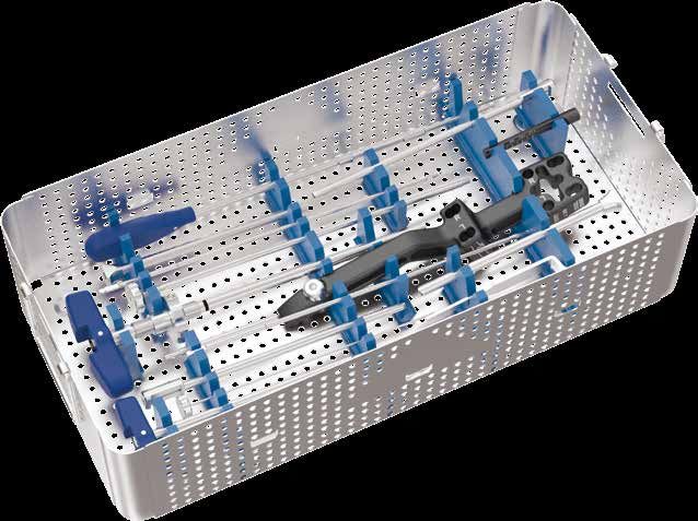
18SE218 - Diaphyseal Screw Guide
SE223 - Freehand Screw Gauge
SE219 - Ø 4.2 mm Diaphyseal Graduated Drill Guide
SE225 - Anti-Rotation Screw Ruler
SE220 - Ø 4.2 mm Drill Bit, 320 mm
SE229A - 240 & 300 mm Nail Targeting Arm
SE221 - Diaphyseal Screwdriver
SE235 - Compression Rod
SE222 - Ø 4.2 mm Drill Bit, 220 mm SE2.S001 - Guide wire set in sterile package Steel AISI 316 LVM - ISO 5832-1
SE20 - Complete tool set
19CAT018EN - Rev. 1 Marzo 2021 - © Intrauma S.p.A. Intrauma S.p.A. - Via Genova, 19 - 10098 Rivoli (TO) Italia Tel. +39.011.953.94.96 - Fax +39.011.958.83.85 info@intrauma.com - www.intrauma.com
You can also read