UNITEC K' in K' Threaded plastic fasteners solutions for plastic assemblies Self-forming - self-tapping - adjustable - reverse-locked
←
→
Page content transcription
If your browser does not render page correctly, please read the page content below
4330/07.02

Colly Components AB. Box 76, 164 94 Kista. Tel 08-703 01 00. Fax 08-703 98 41. www.colly.se

                               UNITEC® K’ in K’
                               Threaded plastic fasteners solutions
                               for plastic assemblies

                               Self-forming – self-tapping – adjustable –
                               reverse-locked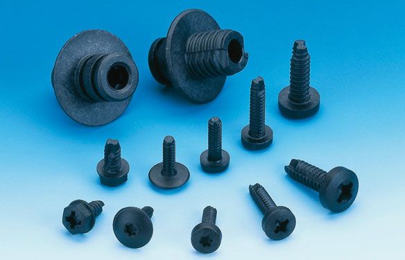
Contents
                                                                Page

           Introduction                                           3

           Effectiveness and functionality of thread profiles      4
           ■ Böllhoff regular thread
           ■ Böllhoff round and high thread

           Details about forming and tapping process               4

           Manufacturing and selection of material                5

           Versions of UNITEC® K’ in K’                           6

           The screws                                             6
           ■ Scopes of functionality
           ■ Repeat of threaded connection
           ■ Mounting hole

           The inserts                                            7
           ■ For ultrasonic welding
           ■ To mechanical turning in

           The systems                                            8
           ■ Screw-in clip
           ■ Screw-in blind rivet
           ■ Body-bound rivet

           Customer benefit                                       10
           ■ Screws
           ■ Inserts
           ■ Systems

           Description of applications                           11

           Scopes of applications                                12

           Our service                                           13

           Technical information                                  13
Introduction
               The assembly of plastic components using plastic screws and thread inserts is largely dependent on the
               mechanical requirements of the joint and whether a permanent or reversible fixing is required. The material
               compatibility of the component and the fastener also proves to be an essential influence.

               Whilst DIN/ISO screws and nuts are the preferred method of de-mountable fastenings into metal fabrications, they
               are often incompatible with the assembly of plastic components. In the medium to long term service life, vibration
               and temperature variations and other external influences can result in failure of the thread connection.

               The Böllhoff solution is the development of plastics in plastic (K’ in K’) screw thread technology with specially
               designed thread profiles. This enables integrated solutions for permanent and reversible fastenings which are
               self-locking, self-tapping, self-forming, adjustable and tolerance compensating. In addition, K’ in K’ screws and
               inserts have been designed specifically for use in thin gauge plastic sheet and plate, thereby increasing the scope
               of UNITEC® in the assembly of engineering plastics.

               The various configurations in the K’ in K’ fastening systems consist of a base section, in the form of a sleeve, rivet,
               clip etc., which retains an aligned screw/insert at the point of assembly. Secure fastenings by means of screw-in
               blind rivet system and screw-in clip system, also exhibit the in-service benefits of dampening vibration and noise
               transfer.

                                                                                                                                     2
                                                                                                                                     3
Effectiveness and functionality of thread profiles
                   The precise thread geometry is fundamental to the effectiveness of K’ in K’ screw fastenings, as the fastener forms
                   or taps a ‘female’ thread into cylindrical, close tolerance, pilot holes.

                   Thread profile:
                   Thread pitch, height of profile, pitch angle as well as the radius at the flank end and flank base, all influence the
                   effectiveness of tapping or forming an internal thread into the parent material. The characteristics of the base
                   material determines the type of K’ in K’ thread profile.

                   Thread forming is determined by either patented option;
                                               Böllhoff K’ in K’ regular thread
                                               or the
                                               Böllhoff K’ in K’ round and high thread

                   The K’ in K’ regular thread is used for screwing into hard plastic materials, where the thread form is cut into a
                   pilot hole.
                   The K’ in K’ round and high thread is preferable for applications where the base material has a higher degree of
                   elasticity and high impact resistance.

                                                        regular thread              round and high tread

                   When which type of thread?

                   Hard solid carrier materials                                  Böllhoff regular thread

                   Carrier materials with high
                   elongation and impact resistance                              Böllhoff round and high thread

Details about forming and tapping process
                   A chip flute, running the length of the screw, enables effective tapping and forming without obstructing the thread
                   flanks. The resulting cutting angle and adjacent clearance angle are at their most effective as the screw assembly is
                   driven home under minimal torque.

                   The Böllhoff K’ in K’ regular thread corresponds to action of a screw tap and the Böllhoff K’ in K’ round and high
                   thread to that of a thread former.
Torque and thread locking
                  The previously described geometry generates a low assembly torque during the process of turning the screw,
                  whilst at the same time preventing any detachment under dynamic stress.

                  Unlike the conventional thread lock on metal screw connections, which can result in strain and surface pressure,
                  the thread lock in the UNITEC® K’ in K’ screw fixing is a result of radial relaxation in the parent material to coalesce
                  with the thread profile of the mating screw.

                                                     Clearance angle                       Direction of rotation

                                                   Chip flute/
                                                   chip angle

                                                                                     Clearance angle

                  Thread connection with fine adjustment
                  The thread locking feature is particularly advantageous when adjusting the height along the axis. In each stepless
                  position (irrespective of the direction of screw rotation) thread locking is maintained by subsequent relaxation of the
                  host plastic, preventing any screw detachment under dynamic load.

                  Examples of applications:
                  ■ Headlight height adjustment
                  ■ Rear light fastening of backlights with adjustment of the gap size
                  ■ Block buffer for service cover flaps

Manufacturing and selection of material
                  The threaded fastener has to have material properties and characteristics which differ from those of the parent
                  plastic. For this purpose selected thread materials are high performance engineering plastics featuring increased
                  temperature resistance and a high degree of rigidity and strength. All of these properties must differ significantly
                  from the host material, in order to maintain the required stability of profile and geometry, when tapping or forming
                  the thread.

                  Preferred basic materials are:
                  ■ PA GF                        high-quality glass filled Polyamide 66
                  ■ PPA GF                       Polyphtalamide glass filled
                  ■ PEI GF                       Polyetherimide glass filled
                  ■ PPS GF                       Polyphenylensulfide glass filled
                  ■ PEEK GF                      Polyetheretherketone glass filled

                  The K’ in K’ screws and inserts are formed from a.m. materials and manufactured according to the material
                  requirements of the injection moulding process.
                  Total accuracy of temperature control within the injection moulding machine and the specially designed tooling is a
                  precondition for achieving premium quality levels throughout the high volume production process.

                                                                                                                                         4
                                                                                                                                         5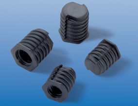
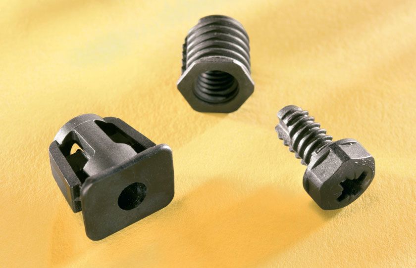
Versions of UNITEC® K’ in K’
                               As previously featured, the development principle of plastic (K’ in K’) thread fastenings provides for coordinated
                               solutions for de-mountable and permanent fixings.
                               Here we differentiate three K’ in K’ options:

                               ■ Screw
                               ■ Insert and
                               ■ Systems.

The screw

The following criteria are integral to final development of a self-forming, self-cutting fastener:

■ Head shape and drive
■ Support and power transmission
■ Thread cutting geometry
■ Thread chamfer

                               The operating sphere of K’ in K’ screw

                               Head design
                               Different styles are available, including

                               ■ DIN EN ISO 7045            slotted pan head screw
                               ■ DIN 34812                  slotted pan head plastic screw
                               ■ DIN 34812                  recessed plastic pan head screw

                               The multi-functional head design can be manufactured,
                               ■ With external hex drive and
                               ■ For the internal drive either a cross slot, socket or inner serration.

                               Support and transmission of force
                               The underside of the head provides a bearing area when the screw is driven into position. The transition to the
                               thread plays an important role in enabling the necessary tapping and reforming work.
                               The dynamic load is absorbed in this zone. In order to spread this dynamic load in a larger area, a conical
                               transition is designed.
                               The ribs beneath the head centres the K’ in K’ screw within the hole of component to be fastened. During the
                               screwing process they support the fastening at a low cross-load.

                               Tapping geometry
                               This area forms and cuts the K’ in K’ thread into the plastic host component. Details q.v. “forming and tapping
                               process”.

                               Chamfer
                               A lead-in chamfer is formed at the base of the thread of a K' in K’ screw. This facilitates centring within the pilot
                               hole and relieves the pressure as it begins rotation to form a thread.

                               Repeatable threaded connection

                               Reversible thread connection of K' in K' screws enables repeated assembly and disassembly without deterioration
                               of the thread, thread locking or overall performance.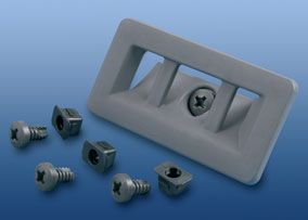
Mounting hole

                             The diameter of any pilot hole has to be such that the central diameter of the K’ in K’ screw is clear of any
                             deformation of the host material. To relieve the setting load, surface countersinking appropriate for the screw size
                             and to a depth of one thread pitch is required. The countersinking aids with the location of the K’ in K’ screw and
                             eases the introduction of the lead-in chamfer.

                             The outer diameter of the countersink is recommended as:

                                                         Surface diameter = size of K’ in K’ screw thread +> 4mm.

                             This dimensional recommendation relates to injection moulded components produced in optimum processing
                             conditions.

                             Factors such as finish, size of chamfer, formation of joint lines in dome wall, as well as the relationship of dome
                             design and load characteristics should be considered when determining the outer diameter.

                             Parts first produced from the mould should be subjected to load testing.

Insert
In these UNITEC® K’ in K’ versions we differentiate between two types of insert.

UNITEC® K’ in K’ for ultrasonic welding
and
UNITEC® K’ in K’ to mechanical turning in

                             Insert for ultrasonic welding

                             On setting, the UNITEC® K’ in K’ plastic insert is sur-
                             rounded by a heat field generated by USS (ultrasonic
                             welding). USS is a technology developed for joining
                             thermoplastic synthetics. The interface of insert and
                             parent material is subject to friction as it absorbs the
                             sonic vibration and the resultant heat plasticises the
                             assembly. In a very short amount of time a positive and
                             homogeneous joint is formed. The required energy is
                             produced in the ultrasonic generator as AC voltage,
                             converted into mechanical vibrations and introduced
                             by the sonotrode. Using this plastic insert in glass filled
                             materials produces even higher resistance threads.
                             When recycling at the end of product life, there is no need for costly and time consuming material separation, as
                             there is with metal inserts.

                             The insert is placed in a conical pilot hole within the parent material and welded ultrasonically. The insert is installed
                             after the component has been moulded.

                             The ultrasonic welding procedure requires the use of identical material classification for both insert and host
                             material. In this way a positive and homogeneous is assured.

                             For the best results, the ultrasound vibration unit should be supplied by recognised manufacturers of ultrasonic
                             welding equipment. Currently metric threads are available in M3, M4, M5, M6 and M8. American/British imperial
                             threads can be supplied.

                                                                                                                                                     6
                                                                                                                                                     7
Mechanical components
Plastic inserts can be screwed in by mechanical means
to introduce a higher faster thread into plastic compo-
nents. The external geometry of the thread is identical
to the K’ in K’ screw (quod vide forming and tapping
process). The precise diameter of the parallel-walled
mounting hole is dependent on the material characteri-
stics of insert and host component and differs
accordingly.
Installation tool
During final installation of the insert it is first spun on to
the spindle of the driver tool and then screwed into the
component. The setting cycle stops when the installa-
tion tool makes contact with the parent carrier part.
Metric female threads in sizes of M3, M4, M5 and M10 can be manufactured. Currently available are sizes of M6
and M8. American/British threads can be manufactured.
The systems
Screw-in clip
A two-part threaded fastening which is waterproof, self-locking and recyclable.
Function
The screw-in clip is first pressed into a pre-prepared square hole in the base component. ➀ A doublelocking
feature results from interference fit of helical flank vanes and underhead pips.
Then the top component is secured by a self-forming K’ in K’ screw engaging with the screw-in clip. ➁ As it turns
in and generates a force along its axis, the female element is pulled up beneath the lower component, folding the
end section and deforming the flank helix under clockwise movement. ➂ A waterproof threaded connection is
produced.
Potential applications:
Anywhere cut threads are not possible in thin wall thickness and/or when production tolerances have to be
adjusted during the assembly process, e.g. industries such as automotive, engineering and plant construction.
➀ ➁ ➂Screw-in blind rivet
The screw-in blind rivet has been developed for fixing through round holes. To prevent rotation on setting, the
surface of the rivet element has an integral flange to lip over the component edge. Other applications are made
possible by an underside hexagonal form to the rivet body.
Function
The screw-in blind rivet is plugged into a hole in the bottom component. ➀ Lateral ribs prevent the rivet from
falling out prior to setting. A mating K’ in K’ screw is located through a hole in the top component to engage with
the internal bore or the rivet and form a thread. ➁
Different riveting thicknesses are no problem for this fastening system, as the screw blind rivet clenches the under-
side of the bottom component, balancing tolerances along its axis as it does so. As the rivet section is drawn up
under thread engagement, it is compressed at the neck and expands to form a blind side fastening. ➂
➀ ➁ ➂
Body-bound rivet
With this fastening system the rivet section forms a
base for the screw.
Body-bound rivets are perfect fastening solutions for
many types of application, principally where access is
restricted to one side of the component. Varying thick-
nesses of material can be joined and the fastening is
particularly effective in thin-walled blow moulded parts.
The rivet element is pressed into a close tolerance hole
within the principal component. A secondary compo-
nent is then screwed into position by a K’ in K’ screw.
As the self-tapping screw is driven into the spread nut
form, the square section is forced to expand and four
external wedges undercut the component to secure a
tight fit.
8
9The advantages
UNITEC® K’ in K’ screw
■ A screw fastening with high reverse-lock
■ Balancing of tolerances by adjustability
■ No corrosion
■ Chemical resistance
■ Electromagnetic compatibility
■ All-plastic fastening solution reduces component weight
■ Capability of recycling – no expensive separating of component parts
■ Minor conductivity of heat/isolator
■ Any colour
UNITEC® K’ in K’ inserts for ultrasonic welding
■ Tension free assembly, especially suitable for brittle materials
■ Higher thread fastness in comparison to spindled thread components
■ High pull-out strength
■ Short times of welding (approx. 0.3 seconds)
■ Very low noise development in welding compared to metal inserts
■ Homogeneous connection between insert and component
■ Capability of recycling – no expensive separating of component parts
■ All-plastic fastening solution reduces component weight
■ Minor conductivity of heat/isolator
■ No corrosion
■ Any colour
UNITEC® K’ in K’ inserts for mechanical turning in
■ A screw fastening with high reverse-lock
■ Balancing of tolerances by adjustability
■ No corrosion
■ Chemical resistance
■ Electromagnetic compatibility
■ All-plastic fastening solution reduces component weight
■ Capability of recycling – no expensive separating of component parts
■ Minor conductivity of heat/isolator
■ Any colour
UNITEC® K’ in K’ systems – screw-in clip
■ Waterproof
■ Fastening requires access from one side only
■ No corrosion
■ Electromagnetic compatibility
■ All-plastic fastening solution reduces component weight
■ Capability of recycling – no expensive separating of component parts
■ Scope of application 0.8 – 2.5 mm thickness of plates for component A
■ Minor conductivity of heat/isolator
■ Fastening solution for thin-walled components
■ Any colourUNITEC® K’ in K’ systems – screw-in blind rivet
■ Fastening requires access from one side only
■ No corrosion
■ Electromagnetic compatibility
■ All-plastic fastening solution reduces component weight
■ Capability of recycling – no expensive separating of component parts
■ Any colour
UNITEC® K’ in K’ systems – body-bound rivet
■ Fastening requires access from one side only
■ No corrosion
■ Electromagnetic compatibility
■ All-plastic fastening solution reduces component weight
■ Capability of recycling – no expensive separating of component parts
■ Thin-walled blow moulding parts
■ Any colour
Description of applications
Threaded connection assembly carrier „Touareg“ (VW)
Self-tapping K’ in K’ screws have been used effectively to fasten a two-part assembly within the interior trim of the
Touareg.
Here the K’ in K’ plastic screw forms its own mating thread within a cylindrical pilot hole set in the base compo-
nent. As the host material relaxes into the longitudinal slot of the screw, a reverse-lock is achieved. Clamp ribs on
the underside of the screw head guarantee an automatic centring of the assembled parts.
Concealed window stop „SMART“ (Daimler Chrysler)
Development of an all-plastic window stop has achieved noise insulation within the side door window plates.
The self-grooving K’ in K’ screw secures the stop, which in turn adjusts to rough tolerance holes in the glass by
means of ribs. The stop is a press fit and a float-free fastening is achieved by the screw.
Fastening the air outlet cover
An air outlet cover made from HD-PE is fastened into a thin walled section by means of a K in K’ screw and
body-bound rivet.
With access available on one side only, the cover is applied to the spread nut and a size 7 L12 K’ in K’ screw is
located and driven home to cut an internal thread. As the screw enters, it splays out the plastic rivet body and
undercuts the material of the host component to achieve a tight fit.
10
11Examples for scopes of application
Böllhoff K’ in K’ screw fastening solutions have been applied in different spheres.
■ Automotive industry, fastening of instrument panel,
threaded connection, assembly carrier, fastening of
headlights
■ Commercial vehicles (lorries, tractors...), tank for
water equalizing
■ Electricity, electronics, safety switch cabinets
■ Office furniture, chairs, desks
■ HVAC
■ Landscape technology, lawn chairs, shield fastenersOur Service
As a specialist service provider, we welcome enquiries for K’ in K’ threaded fasteners and recommend solutions
dependent on the parent material.
The conditions for the most effective threaded fastenings in plastic are many and varied.
These include:
■ Optimal length of screw insertion
■ Required speed of insertion
■ Tightening torque, overwinding torque, screw-in as well as loosening torque
■ Threaded fastening in repeated assembly
The design and production criteria are assessed by assembling samples of original components. If these are not
available at a development stage, test samples are prepared out of selected materials and used for evaluation.
Technical information - mechanical properties
UNITEC® K’ in K’ systems – screw-in clip
Material Thickness Screw-in Tightening Loosening Axial
of carrier of carrier torque torque torque pull-out
mm ME [Nm] MA [Nm] ML [Nm] force F [N]
steel 0.8 - 2.5 0.4 1.3 - 1.5 approx. 1.5 400*
plastic** 0.8 - 2.5 0.4 1.3 - 1.5 approx. 1.5 400*
Rotational speed of screw insertion - 700 revolutions/min
* Thread deformation begins at 400 N, up to destruction at approx. 900 N.
** In a wall thickness of 0.8 mm a glass fibre filled plastic design is recommended. By increasing wall-thickness
the fastness of carrier material can decrease.
UNITEC® K’ in K’ systems – screw-in blind rivet
Material Thickness Screw-in Tightening Loosening Axial
of carrier of carrier torque torque torque pull-out
mm ME [Nm] MA [Nm] ML [Nm] force F [N]
steel 0.8 - 3 0.3 1.2 - 1.6 approx. 1 approx. 400
Rotational speed of screw insertion - 350 revolutions/min
These indicative values have to be related to each specific application.
12
13Technical information – dimensions
UNITEC® K’ in K’ – screws
Part no. Description Dimensions of thread
Böllhoff Thread size Thread length
K’ in K’ thread size l1
0406 730 6012 K’ in K’-screw size 6 L 12 regular thread 6 12
0403 710 6018 K’ in K’-screw size 6 L18 regular thread 6 18
0403 720 6018 K’ in K’-screw size 6 L 18 regular thread 6 18
0403 730 6018 K’ in K’-screw size 6 L 18 regular thread 6 18
0412 730 6020 K’ in K’-screw size 6 L 20 regular thread 6 20
0402 730 6025 K’ in K’-screw size 6 L 25 regular thread 6 25
0403 900 6001 K’ in K’-screw size 6 L 18 regular thread 6 18
0402 730 7012 K’ in K’-screw size 7 L 12 regular thread 7 12
0403 730 7014 K’ in K’-screw size 7 L 14 regular thread 7 14
0403 730 7022 K’ in K’-screw size 7 L 22 regular thread 7 22
0402 790 7001 K’ in K’-screw size 7 L 12 regular thread 7 12
0402 790 7002 K’ in K’-screw size 7 L 12 regular thread 7 12
0402 790 7003 K’ in K’-screw size 7 L 12 regular thread 7 12
0402 790 7004 K’ in K’-screw size 7 L 12 regular thread 7 12
0402 790 7005 K’ in K’-screw size 7 L 12 regular thread 7 12
0402 730 8025 K’ in K’-screw size 8 L 25 regular thread 8 25
0403 730 6418 K’ in K’-screw size 6 L 18 Round high thread 6 18
0403 930 6003 K’ in K’-screw size 6 L 12 Round high thread 6 12
0412 730 7418 K’ in K’-screw size 7 L 18 Round high thread 7 18
for screw-in clip 0400 032 0001
UNITEC® K’ in K’ – special parts
Part no. Description Dimensions of thread
Böllhoff Thread size Thread length
K’ in K’ thread size l1
0419 007 5201 Setting screw regular thread 5.2 12
0419 011 0601 Buffer regular thread 6 19.5
0419 011 0602 Buffer regular thread 6 19.5
0419 013 0601 K’ in K’-screw size 6 L 11.5 regular thread 6 11.5
0419 016 0701 Stud regular thread 7 11
0419 014 0701 K’ in K’-bolt size 7 L 28 (22.8) Round high thread 7 22.8
* On request.
** Material depends on carrier. Alternative materials quo vide page 5.Head version Internal drive External drive Material Colour Comment
Type Outer head- Head height Socket Cross recess (width **
Ø D mm l2 mm across flats)
Pan hexagon 12 5 DIN EN ISO 10664-30 10 PPA GF black
Pan hexagon 12 6 Form Z size 3 10 PPA GF headlight grey
almost RAL 7034
Pan hexagon 12 6 Form Z size 3 10 PPA GF white
Pan hexagon 12 6 Form Z size 3 10 PPA GF black
*
Pan head 15 5 DIN EN ISO 10664-30 PPA GF black
Pan head 16 6 Form Z size 3 PPA GF black
Pan hexagon 12 6 Form Z size 3 PEEK GF natural
*
Pan head 12 4.6 Form Z size 3 PPA GF black
*
Pan hexagon 12 6 Form Z size 3 11 PPA GF black
Pan hexagon 12 6 Form Z size 3 11 PPA GF black
*
Pan head 12 4.6 Form Z size 3 PPA GF green
*
Pan head 12 4.6 Form Z size 3 PPA GF yellow
*
Pan head 12 4.6 Form Z size 3 PPA GF light platinum
*
Pan head 12 4.6 Form Z size 3 PPA GF blue
*
Pan head 12 4.6 Form Z size 3 PPA GF torrone
*
Pan head 15 6 Form Z size 4 PPA GF black
*
Pan hexagon 12 6 Form Z size 3 10 PPA GF black
Pan hexagon 12 6 Form Z size 3 10 PPA GF black
*
Flathead 15 3.5 DIN EN ISO 10665-25 PPA GF black
*
*
Head version Internal drive External drive Material Colour Comment
Type Outer head- Head height Socket Cross recess (width **
Ø D mm l2 mm across flats)
Special head 14 9 T20 with lock nut PPA GF/ black
EPDM-X+PP
*
35 Shore A
Pin head 7.8 10.5 DIN EN ISO 10664-15 4 PPA GF/ black
EPDM-X+PP
*
Rear
73 Shore A external drive
Pin head 7.8 10.5 DIN EN ISO 10664-15 4 PPA GF/ black
EPDM-X+PP
*
Rear
64 Shore A external drive
Flathead 15 6 DIN EN ISO 10664-30 PPA GF black
*
Pin head 10 11 VW 010-43 N5 PPA GF black
Special head - 18.2 15 / 5 PPA GF black
*
*
14
15UNITEC® K’ in K’ – inserts for ultrasonic welding
d1 8°
d a D
L
I
4°
Part no. Description Material** Colour Dimension Total Mounting Minimum Thickness Comment
female length hole bore of carrier
thread d1 l D depth a min.
d mm mm + 0,1mm L mm mm
1631 303 0075 Insert K’ in K’ PA GF
M3 x 7.5 (Blend) black M3 5.8 7.5 5.7 8.5 2.3
1631 304 0009 Insert K’ in K’ PA GF
*
M4 x 9 (Blend) black M4 7 9 6.9 10 2.5
1639 004 0002 Insert K’ in K’
M4 x 9 PEI natural M4 7 9 6.9 10 2.5
1639 304 0001 Insert K’ in K’
M4 x 9 PSU natural M4 7 9 6.9 10 2.5
1631 305 0010 Insert K’ in K’ PA GF
*
M5 x 10 (Blend) black M5 8.6 10 8.5 11 2.8
1631 306 0012 Insert K’ in K’ PA GF
M6 x 12 (Blend) black M6 11 12 10.9 13 3
1631 308 0015 Insert K’ in K’ PA GF
M8 x 15 (Blend) black M8 14 15 13.9 16 4
* On request.
** Further materials available on request.
UNITEC® K’ in K’ – inserts for screw driving installation
Part no. Description Böllhoff Thread size Dimension Total Collar Collar Comment
K’ in K’ thread female length l diameter height
thread M mm D1 mm mm l1
0417 003 08XX Insert K’ in K’ Regular thread
M3x8 6 M3 8 6.8 0.6
0417 004 09XX Insert K’ in K’ Regular thread
*
M4x9 7 M4 9 7.9 0.6
0417 005 10XX Insert K’ in K’ Regular thread
*
M 5 x 10 8 M5 10 9 0.6
0402 006 0003 Insert K’ in K’ Regular thread
*
M6 x 12 10 M6 12 11.3 0.8
0402 008 0004 Insert K’ in K’ Regular thread
*
M 8 x 14 12 M8 14 13.5 0.8
0417 010 16XX Insert K’ in K’ Regular thread
*
M 10 x 16 14 M10 16 15.8 0.8
0419 016 1502 Banjo bolt Left-handed M6 x 7
*
thread 15 x 1.5 15 HITSERT® 15 22 2
0419 016 2303 Banjo bolt Left-handed
*
* Drive internal
thread 23 x 2 23 — 12 — — serration
VW 01043 N18
Selection of material depends on carrier.
* On request.
16UNITEC® K’ in K’ – screw-set fastening elements
K’ in K’ K’ in K’ K’ in K’
screw-in blind rivet screw-in clip spread nut
Part no. Description Screw Total Collar Hole Thickness Material Colour Comment
size/L length l1 height l2 mm of carrier
mm mm mm
0400 032 0001 K’ in K’ screw-in clip
for K’ in K’ screw size 7 PA high-
0412 730 7418 L 18 20 1.6 8x8 0.8-2.5 impact black
0400 132 8002 K’ in K’ screw-in
*
blind rivet for
K’ in K’ screw size 6
0403 730 6418 L 18 26,8 1.3 D 13 0.8-3 PA 66-6 black
0499 046 0026 K’ in K’ spread nut
*
for K’ in K’ screw size 7
0402 790 7001... L 12 9 0.8 10 x 10 1.5 PA 66-6 black
*
* On request.
Colly Components AB. Box 76, 164 94 Kista. Tel 08-703 01 00. Fax 08-703 98 41. www.colly.se
17You can also read