Numerical Transfer Path Analysis for NVH System-Simulation Models - RWTH Aachen
←
→
Page content transcription
If your browser does not render page correctly, please read the page content below

IOP Conference Series: Materials Science and Engineering

PAPER • OPEN ACCESS

Numerical Transfer Path Analysis for NVH System-Simulation Models
To cite this article: Gerwin Pasch et al 2021 IOP Conf. Ser.: Mater. Sci. Eng. 1097 012008

View the article online for updates and enhancements.

                             This content was downloaded from IP address 134.130.185.112 on 30/03/2021 at 16:42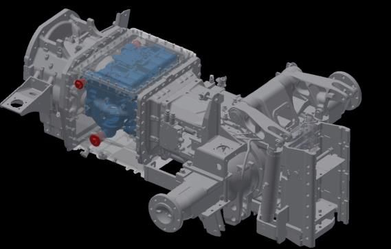
19th Drive Train Technology Conference (ATK 2021)                                                                        IOP Publishing
IOP Conf. Series: Materials Science and Engineering              1097 (2021) 012008           doi:10.1088/1757-899X/1097/1/012008

  Numerical Transfer Path Analysis for NVH System-
  Simulation Models

                        Gerwin Pasch1,2, Georg Jacobs1 and Joerg Berroth1
                        1
                         Institute for Machine Elements and Systems Engineering, RWTH Aachen University,
                        Schinkelstraße 10, 52062 Aachen, Germany
                        2
                         gerwin.pasch@imse.rwth-aachen.de

                        Abstract For the assessment of the Noise, Vibration and Harshness (NVH) behavior of complex
                        systems in early phases of the development process, validated modelling methods are available
                        that allow the prediction of structure-borne and airborne noise at system level. However, due to
                        large model sizes, the identification of weak spots in the vibroacoustic transfer behavior and the
                        derivation of optimization measures are highly complex, time-consuming, and mostly not
                        practical. In the field of experimental NVH analysis, transfer path analysis (TPA) has been
                        established as target-oriented methods for identifying vibroacoustic anomalies at system level.
                        In this contribution, TPA methods from the field of measurement technology are selected and
                        applied to numerical NVH system models, aiming for high accuracy and low computational
                        effort in post-processing. The applications of the methods are shown and discussed using an
                        elastic multi-body simulation model of a tractor drivetrain with a transient run-up of the vehicle
                        speed as an example. The classical direct-force and component-based blocked-force TPA
                        methods selected and adapted for this study allow for efficient calculation of the sound
                        contributions of numerical models. At the same time, they overcome typical challenges of
                        experimental TPA, such as exact force determination or consideration of rotational degrees of
                        freedom. In addition, the comparison of the two methods shows that the path contributions are
                        in general different for classical and component-based TPA and only under specific conditions
                        the same. Both numerical TPA methods allow for the identification of weak spots in the NVH
                        behavior in an efficient and target-oriented way.

  1. Introduction
  Manufacturers and suppliers are increasingly aiming to shorten development times and reduce
  development costs in order to remain competitive in the market. Long development times and high costs
  are mainly caused by prototypes, measurements and product changes in late phases of the product
  development process (PDP). To reduce the number of prototypes and measurements to a minimum and
  to avoid changes in prototyping phase, methods of virtual product development are currently used in
  many industrial sectors.
     In addition to the central goal of function fulfilment, comfort features such as the Noise, Vibration
  and Harshness (NVH) behavior are increasingly becoming the focus of attention for customers and
  consumers and are therefore an important requirement and development goal. The NVH behavior
  describes all audible and perceptible vibrations on machines and vehicles. According to the machine
  acoustic transfer chain, sound arriving at a receiver point, e.g. the driver’s ear, is characterized by
  excitation, transmission and radiation properties. Sound is transmitted along airborne or structure-borne
  sound paths, the so-called transfer paths. The propagation of structure-borne sound depends on the

              Content from this work may be used under the terms of the Creative Commons Attribution 3.0 licence. Any further distribution
              of this work must maintain attribution to the author(s) and the title of the work, journal citation and DOI.
Published under licence by IOP Publishing Ltd                          1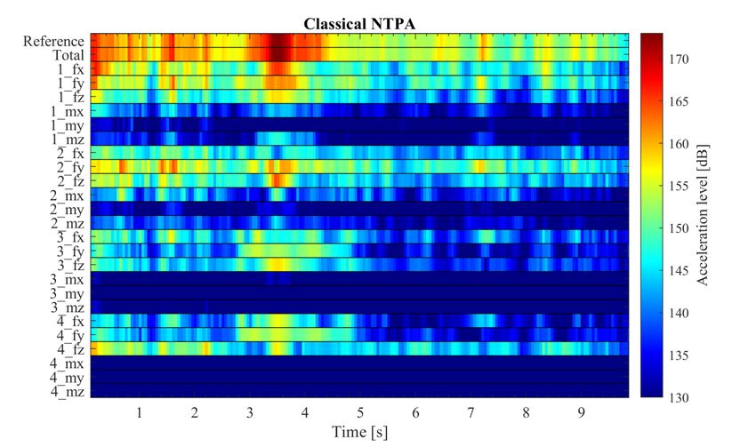
19th Drive Train Technology Conference (ATK 2021)                                               IOP Publishing
IOP Conf. Series: Materials Science and Engineering   1097 (2021) 012008   doi:10.1088/1757-899X/1097/1/012008

structural dynamics of the individual subsystems as well as on their couplings and thus on the system
topology. Due to the high dependencies and interactions, the prediction of the NVH behavior requires
investigations at system level. In the field of virtual product development, numerous validated modelling
methods are available today which provide reliable noise predictions for entire systems up to the medium
and higher frequency range (
19th Drive Train Technology Conference (ATK 2021)                                                         IOP Publishing
IOP Conf. Series: Materials Science and Engineering          1097 (2021) 012008      doi:10.1088/1757-899X/1097/1/012008

effects caused by phase differences, that result in increasing or decreasing sound amplitudes. The sound
contributions help to determine dominant sources or paths in a structured and target-oriented way. The
sound contributions are calculated by multiplying forces or sound quantities from operational
measurements with measured transmission properties. According to the paradigm of dynamic
substructuring [5], the considered system AB is therefore divided, i.e. substructured, into the subsystems
A and B, Figure 1.
                                                  System AB

                                Subsystem A                                Subsystem B

                                       A          A                   B
                                      Y21        Y22                 Y22     B         u3path
                          f1                                                Y32
                                                                                             u3
                                                                                  u3path i

                         1: Source                    2: Interfaces                  3: Receiver
                  Figure 1. General procedure for TPA: substructuring of the System AB.

    The interfaces and thus the paths are determined by the choice of the cutting plane. Subsystem A is
usually the active side which contains the excitation sources with the excitation forces f1 . Subsystem B
is the passive side which is excited by system A via several interfaces and which contains the receiver
points. The analyzed sound quantity u can be displacements, velocities or accelerations. The complex-
valued summation of the sound contributions u3path i of all n paths results in the total sound u3 at the
receiver point:
                                                      n
                                        u3 = ∑              u3path i                                               (1)
                                                      i=1
    The transfer characteristics of the structure are described in the form of the frequency response
                    A    A     B       B
functions (FRFs) Y21  , Y22 , Y22 and Y32 . The superscript indices indicate the subsystem and the subscript
indices indicate the points between the FRFs are obtained.
Over the last decades various TPA methods have been developed. In [6], an overview and a classification
of the methods is given. The methods are divided into three TPA families:

     •   Classical TPA
     •   Component-based TPA
     •   Transmissibility-based TPA

    The classical and the component-based TPA are physical methods, whereas the transmissibility-
based TPA is based on correlations and statistics. The transmissibility-based TPA offers the advantage
of a reduced measurement effort. For application to numerical models, the measurement effort is
irrelevant. In this publication, only the two physical methods will be discussed.
    The calculation of classical and component-based TPA can be derived using the general approach
for substructuring. On the conditions of displacement compatibility uA          B
                                                                          2 = u2 and force equilibrium
gA      B
  2 + g 2 = 0 in the interfaces, the total sound u3 at the receiver caused by the source force f1 can be
determined as follows:
                                       B     A     B −1 A                                                          (2)
                                 u3 = Y32 ·(Y22 + Y22 ) ·Y21 ·f1
   For both, classical and component-based method, the sound contributions are determined from time-
dependent forces and frequency-dependent transmission properties in the form of FRFs. The methods

                                                                 3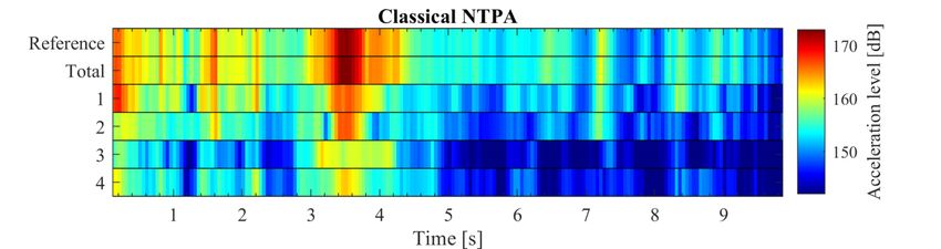
19th Drive Train Technology Conference (ATK 2021)                                                       IOP Publishing
IOP Conf. Series: Materials Science and Engineering     1097 (2021) 012008    doi:10.1088/1757-899X/1097/1/012008

differ in how the quantities of equation (2) are combined. The selected combination results in different
subdivisions of the overall system for the measurements.
    In classical TPA, the forces are determined in the assembled system AB. These forces correspond to
cutting forces respectively interface forces. The FRFs are determined in the isolated passive structure
B. The product of interface forces g B2 and FRFs Y32
                                                   B
                                                      provides the path contributions.
                                  B     A     B −1 A           B B                                                (3)
                            u3 = Y32 ·(Y22 + Y22 ) ·Y21 ·f1 = Y32 ·g 2
    with
                                     g B2 = (Y22
                                              A     B −1 A
                                                 + Y22 ) ·Y21 ·f1                                                 (4)
                                                          A
   For the component-based TPA, the equivalent forces feq    are determined which depend only on the
                                                               AB
source structure A. Together with the transmission properties Y32 , determined in the assembled system
AB, the path contributions are calculated. The derivation is shown in (5), where (2) is extended by
 A     A −1
Y22 ·(Y22 ) .
                         B     A     B −1 A       A −1 A           AB A
                   u3 = Y32 ·(Y22 + Y22 ) ·Y22 ·(Y22 ) ·Y21 ·f1 = Y32 ·feq                                        (5)
    with
                                    AB    B     A     B −1 A                                                      (6)
                                   Y32 = Y32 ·(Y22 + Y22 ) ·Y22
    and
                                         A      A −1 A
                                        feq = (Y22 ) ·Y21 ·f1                                                     (7)
    As shown in equation (7), the equivalent forces are dependent only on the active system A.

   In experimental TPA, the determination of forces is challenging. Since the integration of force
sensors changes the structural dynamics of the system, methods for indirect force determination were
developed. For this purpose, acceleration or displacement quantities and transmission properties are
measured, from which the forces are subsequently determined, for example by matrix inversion. An
overview of the methods is given in Table 1, that is an excerpt of [6].

                  Table 1. Overview and classification of TPA methods according to [6].

 Family
                  Method                Operational measurement       Source characterization              Apply to

                                        Quantity      On system       Quantity                  Using      FRFs

                  Direct-force          g B2          AB              Interface force   g B2    −           B
                                                                                                           Y32
 Classical        Mount-stiffness       uA2 , uB2     AB              Interface force   g B2    Z mt        B
                                                                                                           Y32
                  Matrix-inverse        u4            AB              Interface force   g B2     B
                                                                                                Y42         B
                                                                                                           Y32
                                                                                         eq
                  Blocked-force         g bl
                                          2           A (blocked)     Equiv. force      f2      −           AB
                                                                                                           Y32
                                                                                         eq
                  Free-velocity         ufree
                                         2            A (free)        Equiv. force      f2       A
                                                                                                Y22         AB
                                                                                                           Y32
 Component-                                                                              eq
                  Hybrid-interface      g R2 , u2     AR              Equiv. force      f2       A
                                                                                                Y22         AB
                                                                                                           Y32
 based
                                                                                         eq      AR/AB      AB
                  In-situ               u2 (u4 )      AR/AB           Equiv. force      f2      Y22 (42)   Y32
                                                                                                 AR/AB      AB
                  Pseudo-forces         u4            AR/AB           Pseudo force      fps     Y4ps       Y3ps

                                                            4
19th Drive Train Technology Conference (ATK 2021) IOP Publishing
IOP Conf. Series: Materials Science and Engineering 1097 (2021) 012008 doi:10.1088/1757-899X/1097/1/012008
Only for the classical direct-force and the component-based blocked-force method, the forces are
determined directly without further calculations. For all other methods, the forces are determined
indirectly e.g. with mathematically expensive operations like matrix inversion. The blocked-force
method uses the fact that the equivalent forces are equal to forces that fixate the active system rigidly.
These forces are called blocked forces g bl
2 and can be derived with the boundary condition uA = 0.
A A bl (8)
uA = 0 = Y21 ·f1 − Y22 ·g 2
By rearranging equation (8) the following is obtained:
g bl A −1 A
2 = (Y22 ) ·Y21 ·f1 (9)
A
This corresponds exactly to the equivalent forces feq shown in equation (7) that shows that both
forces are equal.
The use of TPA for the evaluation of numerical models is known in the literature as numerical TPA
(NTPA). In previous publications the application of two TPA methods to numerical models has been
shown, although in each case only under consideration of a single operation point: [7] and [8] show the
applications of the classical direct-force method. In [9], the application of the component-based in-situ
method for a linearized system in frequency domain is presented. Due to the indirect force determination
of the in-situ method, extensive post-processing is necessary. The advantage of numerical models of
direct availability of forces without further complex calculations is not used.
In contrast, this publication extends the NTPA methods by the component-based blocked-force
method to achieve high accuracy and low computational effort. The parallel use of the classical direct-
force method allows for a direct comparison of the sound contributions between the classical and
component-based TPA families.
3. Solution approach
In early phases of the PDP, elastic multi-body simulation (EMBS) is widely used for analyzing the
NVH behavior of virtual prototypes. The EMBS enables efficient calculation of the structural dynamics
of large, flexible structures considering non-linear transmission elements and transient excitations under
variable operating conditions in frequency as well as in time domain. Coupling elements such as
bushings or roller bearings are typically modeled using concentrated force elements. Variables like
acceleration or forces can be determined at any desired location in the system. Typical weaknesses of
experimental TPA, such as exact force determination, consideration of rotational degrees of freedom,
installation space limitations and measurement noise, do not exist for numerical simulations.
For selecting of suitable TPA methods for the application to numerical models, two requirements in
particular are considered: high accuracy and low computational effort especially in post-processing. The
two requirements are met by selecting physical TPA methods with direct-force determination. As
described above, the concentrated force elements of the EMBS allow for direct force signal output at
interfaces without further calculations. The amount of data exchanged is also kept low by the direct-
force determination, which enables efficient calculation in the post-processor. Therefore, the classical
TPA with direct-force and the component-based TPA with blocked-force determination are selected.
For both methods the procedure and the calculation chain were created. Each method requires two
separate simulations which can be derived based on an initial model covering the overall system AB.
The methods differ mainly in the definition of the system boundaries of the simulation models.
Figure 2 shows the method proposed for determining path contributions according to the classical
TPA method with direct-force determination for numerical models.
519th Drive Train Technology Conference (ATK 2021) IOP Publishing
IOP Conf. Series: Materials Science and Engineering 1097 (2021) 012008 doi:10.1088/1757-899X/1097/1/012008
= Time Interface
Integration DFT Forces
Classical NTPA
1 B B
g () g ( , f)
Path
Contributions
YpB t i · g Bp t i Visualization
LSA FRFs
2 Y B (f)
EMBS Post-Processing
Figure 2. Proposed method for performing classical NTPA with direct-force determination.
As shown in the previous section, in classical TPA the interface forces are obtained in the assembled
system AB. Using time integration, the time-dependent interface forces are calculated in time domain
for example for a run-up of a drivetrain. Both, translational and rotational forces are directly available
as output variables. Using discrete Fourier transform (DFT), the time signals are transferred into
frequency domain. The FRFs for the classical NTPA are determined in frequency domain on the passive
structure using linear system analysis (LSA) calculation. For this purpose, the active subsystem is
deactivated in the simulation model. The FRFs are determined successively between all interface
degrees of freedom (DOFs) and the receiver DOFs. The path contributions are obtained by multiplying
the complex-valued forces and FRFs.
The proposed method for determining path contributions using the component-based TPA method
with blocked-force determination for numerical models is presented Figure 3.
= Time Equivalent
Comp.-based NTPA
Integration DFT Forces
1 f eq ( ) f eq ( , f)
Path
eq Contributions
YpABt i · fp t i Visualization
2 LSA FRFs
Y AB (f)
EMBS Post-Processing
Figure 3. Proposed method for performing component-based NTPA with blocked-force
determination.
The equivalent forces required in the component-based TPA equals to the so-called blocked forces.
The blocked forces are determined by fixing the source structure to an infinitely stiff environment. In
the model this is achieved by deactivating the passive structure and connecting the interfaces to the
ground. The LSA is performed on the assembled system. The operations for post-processing are the
same as in the classical method.
The number of paths results from the number of interface DOFs and receiver DOFs. In general, all
force-transmitting interface DOFs should be considered. Receiver DOFs can be freely selected by the
user according to his interests. Translational as well as rotational DOFs can be considered. For clarity,
individual paths can be summarized in the visualization tool. For example, the interface DOFs of
individual interfaces can be summarized and the receiver DOFs can be combined to one receiver signal.
4. Application of NTPA to a tractor drivetrain
The NTPA methods presented above are applied to a demonstrator EMBS model for illustration. A
validated model of a tractor drivetrain with a hydrostatic-mechanical power split transmission is used,
which is described in detail in [3]. The model used in this study is shown in Figure 4.
619th Drive Train Technology Conference (ATK 2021) IOP Publishing
IOP Conf. Series: Materials Science and Engineering 1097 (2021) 012008 doi:10.1088/1757-899X/1097/1/012008
3
1
4 R Inner housing Drivetrain housing
1
2 Bushings
2 3 R
4
Hydrostatic units Cabin suspension
Figure 4. EMBS model of a tractor drivetrain as demonstrator for NTPA.
The main excitation source of the system are the hydrostatic units of the drivetrain. The hydrostatic units
are mounted in a separate inner housing and connected to the drivetrain housing elastically via four
elastomer bushings. In the NTPA, the paths from the bushing suspensions to the cabin suspension are
considered. Therefore, the cutting plane is placed along the bushings. In the following study, the cabin
suspension front right, marked with ‘R’ in Figure 4, is selected as the receiver point. The bushings
transmit both translational and rotational forces along all DOFs. This results in six possible interface
DOFs per bushing, in total 24 interface DOFs. In this example the total translational acceleration at the
receiver is considered.
Using the methods shown in section 3, the sound contributions are calculated for the tractor drivetrain
for a transient run-up of the vehicle speed. For verification of the calculation, the acceleration level at
the receiver point measured in the reference model is compared with the synthesized total acceleration
level generated by the NTPA using equation (1). The results are shown in Figure 5.
5 dB
Figure 5. Comparison of the simulated and synthesized acceleration levels at the receiver.
The acceleration signals show a high degree of conformity. Small deviations of maximum 1-2 dB
are visible. These deviations can be caused by effects of linearization or numerical inaccuracies. The
deviations are relatively small and do not influence the qualitative results of the NTPA. Overall, the
diagram shows a high accuracy of the calculation for both methods.
In the following the results of the NTPA are presented in the form of the sound contributions. As
mentioned above, the sound contributions can be evaluated on different levels for visualization purposes.
Figure 6 shows the sound contributions of the four bushings to the total sound for the classical NTPA.
For comparison, the acceleration level of the reference model is presented in the first row.
719th Drive Train Technology Conference (ATK 2021) IOP Publishing
IOP Conf. Series: Materials Science and Engineering 1097 (2021) 012008 doi:10.1088/1757-899X/1097/1/012008
10 dB
Figure 6. Classical NTPA: Total sound contributions of the bushings.
The color bars indicate the acceleration level of the individual paths. This visualization allows for a
transparent identification and ranking of dominant paths. For example, it becomes clear that the peak at
the time 3.5 s is mainly caused by bushings 1 and 2.
For a more in-depth investigation, the contributions of the bushings are divided into the six interface
DOFs, Figure 7.
5 dB
Figure 7. Classical NTPA: Sound contributions of the bushings divided into six interface DOFs.
It is visible that especially the paths in x- and y-direction of bushing 1 and y- and z-direction of
bushing 2 have the highest contribution to the total sound.
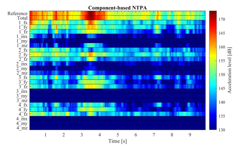
The result of the component-based NTPA is shown in Figure 8.
819th Drive Train Technology Conference (ATK 2021) IOP Publishing
IOP Conf. Series: Materials Science and Engineering 1097 (2021) 012008 doi:10.1088/1757-899X/1097/1/012008
5 dB
Figure 8. Component-based NTPA: Sound contributions of the bushings divided into six interface
DOFs.
The results are similar to the results of classical NTPA, although not exactly the same. For example,
the path of bushing 2 in z-direction is less dominant in component-based NTPA in comparison with
classical NTPA with a difference of about 8 dB at the time 3.5 s. The reason for the differences in the
sound contributions of the two methods will be discussed in the following section.
5. Discussion
The results presented in section 4 show that TPA can be performed on numerical models with the
proposed calculation chains. The comparison between the simulated and synthesized acceleration levels
at the receiver demonstrates the high accuracy of the calculation, as presented in Figure 5. Weak spots
in the complex transfer behavior become clearly detectable by the visualization of the sound
contributions in the color bar diagrams, Figure 6-8. These results can be used directly to derive
optimization measures, such as a stiffening of the passive-side connection of the bushing.
The calculation time of the post-processing including the visualization takes only few minutes.
Therefore, the routines developed in this study are well applicable in the PDP. Among them, the
component-based NTPA with blocked-force determination offers another essential advantage:
significant reductions of the calculation times of the time integration simulation. The time integration
for this method was performed only on subsystem A and not on the overall system due to the
substructuring strategy presented. Depending on the system, this can lead to significant reductions in
calculation time. In the case of the tractor model, the calculation times for time integration were reduced
by about 50%. Another advantage of the component-based method is that the blocked forces depend
only on system A. In the case that changes or optimization measures are applied to system B, the blocked
forces remain unchanged. For this reason, only an LSA calculation with its short calculation times (few
seconds or minutes) must carried out to evaluate optimization measures. Thus, the sound contributions
for a modified system can be generated within a few minutes.
As mentioned in the previous section, the sound contributions of the classical and component-based
methods are similar but not equal for the system under study. While the total sound at the receiver u3 is
919th Drive Train Technology Conference (ATK 2021) IOP Publishing
IOP Conf. Series: Materials Science and Engineering 1097 (2021) 012008 doi:10.1088/1757-899X/1097/1/012008
mathematically the same for both methods, the path contributions of the two methods are in general not
equal. This is caused by the different way of substructuring and thus the different calculation order of
equation (2). The difference in the mathematical calculation is derived in the following for one frequency
grid point. For clarity, equation (2) is rewritten as
u3 = A · B · C (10)
with
B
A = Y32 ∈ ℂ1xn (11)
A B −1 A (12)
B = (Y22 + Y22 ) ·Y22 ∈ ℂnxn
A −1 A (13)
C = (Y22 ) ·Y21 ·f1 ∈ ℂnx1
The dimension n corresponds to the number of interface DOFs. In the case of classical TPA, entry i
of A is multiplied by entry i of the matrix product of B and C for calculation of the sound contribution
of path i:
ucl ssic
3path i = Ai · (B · C)i (14)
For calculation of the sound contribution of path i in component-based TPA, entry i of the matrix
product of A and B is multiplied by entry i of C:
comp.
u3path i = (A · B)i · Ci (15)
In general, equations (14) and (15) are not equal, and thus the path contributions of classical TPA
and component TPA are not the same.
In the special case that B is diagonal, equations (14) and (15) and thus the path contributions of both
methods are the same. B is diagonal when no crosstalk between the interface DOFs exists, because
crosstalk is indicated by the side diagonal entries of B. Crosstalk means that a force at one interface
DOF causes a response, e.g. movement or force, at another interface DOF. The level of crosstalk
depends on the system and on the definition of the cutting plane. The special case of a system without
crosstalk can also be illustrated as follows: an equivalent force acting at one interface DOF in the system
AB causes only an interface force at the same interface DOF, whereas the interface forces at all other
DOFs are zero.
However, real systems typically exhibit a certain amount of crosstalk. In the case of the tractor
drivetrain presented in the previous section, this amount is relatively small, resulting in slightly different
sound contributions for the two methods.
In systems with a high level of crosstalk, the results of the two methods can vary significantly, leading
to different interpretations and optimization measures for the systems in question. Hence, the choice of
method should be guided by the specific changes and optimization measures to be evaluated. For a fully
filled matrix B, in classical TPA a sound contribution ucl ssic
3path i contains exactly one transfer path between
an interface DOF and the receiver, and n forces acting within the interface DOFs. In contrast, for
comp.
component-based TPA with a fully filled matrix B, a sound contribution u3path i results from n transfer
paths between the interface DOFs and the receiver, with exactly one equivalent force acting at one
interface DOF. Thus, classical TPA can provide more transparent results for evaluating of single transfer
path changes in the passive system. The results of the component-based TPA, on the other hand, can be
more transparent for evaluating optimizations that aim to change a force dependent on the active system.
1019th Drive Train Technology Conference (ATK 2021) IOP Publishing
IOP Conf. Series: Materials Science and Engineering 1097 (2021) 012008 doi:10.1088/1757-899X/1097/1/012008
6. Summary and Outlook
This contribution shows the application of the classical and component-based TPA methods to
numerical elastic multi-body system-simulation models and their comparison. The classical direct-force
and component-based blocked-force TPA methods were chosen for achieving high accuracy with low
computational effort even for the analysis of wide and transient operation ranges. Both methods are
challenging for use in experimental TPA because of the direct way of force determination, but
particularly suitable for the application to numerical models. The calculation chains developed for both
methods were applied to a demonstrator model of a tractor drivetrain for investigating the structure-
borne noise for a transient run-up of the vehicle speed. The NTPA allows for in-depth insights into the
system behavior with low computational effort. The efficient and target-oriented analysis tool is suitable
for being used in early phases of the product development process for identifying optimization potential
in a transparent and structured way. It was shown that the component-based blocked-force method
additionally offers a high potential for the reduction of simulation time. Since the classical and the
component-based NTPA were carried out in parallel, a direct comparison of the sound contributions was
possible, whereby slight differences were identified for the demonstrator model. Further investigations
showed that these differences are caused by the different calculation order of the path contributions for
the two methods. Both methods provide equal path contributions only for systems without crosstalk,
which are barely found in reality. For systems with high crosstalk, on the other hand, a theoretical
discussion is given about which method allows evaluating optimization changes with higher
transparency.
In this contribution, the NTPA was presented on structure-borne sound level. In further works, the
calculation chain of classical NTPA presented in this study has been extended in order to perform path
evaluations on airborne sound level for numerical system-simulation models [10].
Furthermore, the NTPA methods are to be integrated into automated optimization processes. The
component-based NTPA method is particularly suitable for this purpose due to its high potential for
reducing simulation times. Especially for optimizations on the passive system, only FRF calculations
are required per iteration, so that each iteration can be performed within few minutes.
References
[1] Drichel P, Jaeger M and Müller-Giebeler M 2019 Mit elektrischem Antrieb und modellbasierter
Systemanalyse nahezu lautlos in die Zukunft ATZ Extra pp 52–57
[2] Jaeger M, Drichel P, Müller-Giebeler M, Schröder M, Berroth J, Behler G, Hameyer K, Jacobs
G and Vorländer M 2019 Erweiterung NVH Simulationsmodell: Erweiterung der
Simulationsmöglichkeiten für maschinenakustische Untersuchungen an E-Motive-Antrieben
im Kontext zur Fahrzeugstruktur FVA Heft Nr. 1730 (Forschungsvereinigung Antriebstechnik
e.V.)
[3] Pasch G, Jacobs G, and Berroth J K 2020 NVH System Simulation of a Tractor with Hydrostatic-
Mechanical Power Split Transmission LANDTECHNIK 75(4) pp 301-15
[4] Rick S, Klein J, Wegerhoff M, Hameyer K, Vorländer M and Jacobs G 2015 E-MOTIVE NVH-
Simulationsmodell: Modellbildung zur NVH Simulation eines E-MOTIVE Antriebsstrangs
FVA Heft Nr. 1130 (Forschungsvereinigung Antriebstechnik e.V.)
[5] Klerk D de, Rixen D J and Voormeeren S N 2008 General Framework for Dynamic
Substructuring: History, Review and Classification of Techniques AIAA Journal 46 pp 1169–
81
[6] van der Seijs, Maarten V., Klerk D de and Rixen D J 2016 General framework for transfer path
analysis: History, theory and classification of techniques Mechanical Systems and System
Processing pp 217-44
1119th Drive Train Technology Conference (ATK 2021) IOP Publishing
IOP Conf. Series: Materials Science and Engineering 1097 (2021) 012008 doi:10.1088/1757-899X/1097/1/012008
[7] Vanhollebeke F, Peeters J, Vandepitte D and Desmet W 2015 Using transfer path analysis to
assess the influence of bearings on structural vibrations of a wind turbine gearbox Wind
Energy 18 pp 797–810
[8] Acri A, Offner G, Nijman E and Corradi R 2015 NUMERICAL TRANSFER PATH ANALYSIS
FOR THE ASSESSMENT OF AIR-BORNE NOISE IN INTERNAL COMBUSTION ENGINES
Proceedings of ICoEV 2015, International Conference on Engineering Vibration: Ljubljana,
7-10 September (Ljubljana: Faculty for Mechanical Engineering) pp 384–93
[9] Wegerhoff M, Sottek R and Amberg J 2018 Numerical in-situ TPA of an elastic multibody
dynamic model of a tractor gearbox AAC 2018: Aachen Acoustics Colloquium/Aachener
Akustik Kolloquium ed S Pischinger et al (Aachen, Germany: FEV Group GmbH) pp 177–88
[10] Wischmann S, Pasch G, Berroth J and Jacobs G 2021 Acoustic Optimization of a Power Take-off
Gear Box Using Numerical Transfer Path Analysis IOP Conference Series, Material Science
and Engineering
12You can also read