Transport and Main Roads Specifications MRTS233 Roadway Flood Monitoring Systems - Technical Specification
←
→
Page content transcription
If your browser does not render page correctly, please read the page content below
Technical Specification

Transport and Main Roads Specifications
MRTS233 Roadway Flood Monitoring Systems
July 2019
Copyright
© The State of Queensland (Department of Transport and Main Roads) 2019.

Licence

This work is licensed by the State of Queensland (Department of Transport and Main Roads) under
a Creative Commons Attribution (CC BY) 4.0 International licence.

CC BY licence summary statement
In essence, you are free to copy, communicate and adapt this work, as long as you attribute the
work to the State of Queensland (Department of Transport and Main Roads). To view a copy of this
licence, visit: https://creativecommons.org/licenses/by/4.0/

Translating and interpreting assistance
              The Queensland Government is committed to providing accessible services to
              Queenslanders from all cultural and linguistic backgrounds. If you have difficulty
              understanding this publication and need a translator, please call the Translating and
              Interpreting Service (TIS National) on 13 14 50 and ask them to telephone the
              Queensland Department of Transport and Main Roads on 13 74 68.

Disclaimer
While every care has been taken in preparing this publication, the State of Queensland accepts no
responsibility for decisions or actions taken as a result of any data, information, statement or
advice, expressed or implied, contained within. To the best of our knowledge, the content was
correct at the time of publishing.

Feedback
Please send your feedback regarding this document to: tmr.techdocs@tmr.qld.gov.au

Transport and Main Roads Specifications, July 2019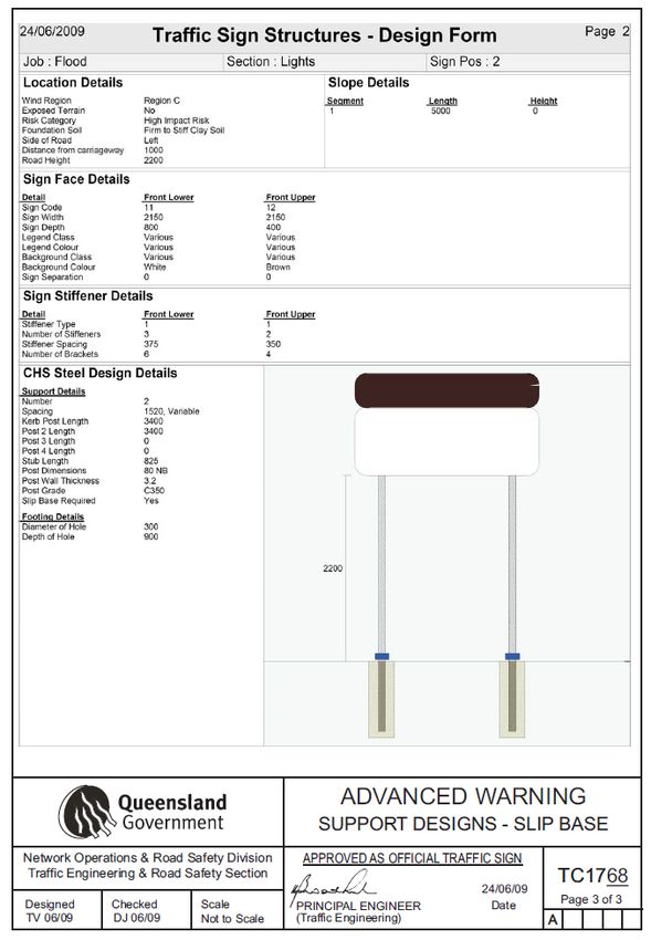
Contents
1       Introduction ....................................................................................................................................2
2       Definition of terms .........................................................................................................................2
3       Reference documents ...................................................................................................................3
4       Quality system requirements .......................................................................................................3
5       Functional requirements ...............................................................................................................4
6       RFMS components ........................................................................................................................4
7       Operational requirements .............................................................................................................4
7.1     Security requirements ..................................................................................................................... 5
8       Flood level sensor requirements .................................................................................................6
8.1     Environmental requirements ........................................................................................................... 6
8.2     Performance requirements ............................................................................................................. 6
8.3     Electrical requirements ................................................................................................................... 6
8.4     Mechanical/material requirements .................................................................................................. 6
9       Road signage .................................................................................................................................7
10      Imaging equipment ........................................................................................................................7
11      Control system ...............................................................................................................................7
11.1 General ........................................................................................................................................... 7
11.2 STREAMS device driver ................................................................................................................. 8
11.3 System local control ........................................................................................................................ 8
11.4 System remote control .................................................................................................................... 8
11.5 Internal clock ................................................................................................................................... 9
11.6 Communication protocol ................................................................................................................. 9
12      Mechanical and physical requirements .......................................................................................9
13      Electrical requirements .............................................................................................................. 10
13.1 Mains power.................................................................................................................................. 10
13.2 Battery power ................................................................................................................................ 10
13.3 Solar power ................................................................................................................................... 10
13.4 Protection against electrical transients and over-voltage ............................................................. 10
14      Telecommunications requirements .......................................................................................... 10
15      Installation requirements ........................................................................................................... 10
16      Testing and commissioning ...................................................................................................... 10
17      Documentation ............................................................................................................................ 11
18      Training ........................................................................................................................................ 11
19      Maintenance ................................................................................................................................ 11
20      Handover ..................................................................................................................................... 12
Appendix A ........................................................................................................................................... 13

Transport and Main Roads Specifications, July 2019                                                                                                         i
Technical Specification, MRTS233 Roadway Flood Monitoring Systems

1        Introduction
This Technical Specification defines the design, supply, installation, testing and commissioning,
performance, documentation, training and maintenance requirements for roadway flood monitoring
systems (RFMS).

The RFMS is intended to supplement an overall weather monitoring system strategy to improve
incident response and driver safety.

The basic RFMS is an electrically powered system consisting of a flood level sensor, data
logger/controller, antenna and communications equipment tilt pole support structure and some means
of backhaul communication (usually wireless) to a remote head end Traffic Management Centre
(TMC) to enable monitoring of roadway flood height data, and optionally roadway flood monitoring
imaging.

Auxiliary devices or systems connected to the basic RFMS include Road Condition Information Signs
(RCIS) and CCTV cameras with or without infra-red illumination for night viewing.

This Technical Specification shall be read in conjunction with MRTS01 Introduction to Technical
Specifications, MRTS50 Specific Quality System Requirements and other Technical Specifications as
appropriate.

The Principal may elect an outright purchase model or a lease type model for all or part of the RFMS
specified in this Technical Specification.

This Technical Specification forms part of the Transport and Main Roads Specifications Manual.

    In this version references to the new MRTS263 Standalone Solar (PV) Power Systems were made.

2        Definition of terms
The terms defined in Clause 2 of MRTS01 Introduction to Technical Specifications and
MRTS01 Introduction to Technical Specifications apply to this Technical Specification. Additional
terminology relevant to this Technical Specification is defined in Table 2 below.

Table 2 – Definitions

           Term                                            Definition
    BoM                 Bureau of Metrology
    FAT                 Factory Acceptance Test
    FP                  Field Processor
    GUI                 Graphical User Interface
    IP                  Internet Protocol
    IPRT                Internet Protocol Remote Telemetry (the department’s core ITS Network supplied
                        by Telstra)
    ITS                 Intelligent Transport System
    PLC                 Programmable Logic Controller
    RFMS                Roadway Flood Monitoring System(s)
    RPEQ                Registered Professional Engineer of Queensland

Transport and Main Roads Specifications, July 2019                                                     2
Technical Specification, MRTS233 Roadway Flood Monitoring Systems
Term Definition
STREAMS The Principal’s traffic management system and primary user interface to ITS field
devices
TMC Traffic Management Centre
TRUM Traffic Road Use Manual
3 Reference documents
The requirements of the referenced documents listed in Table 3 of MRTS201 General Equipment
Requirements and Table 3 below apply to this Technical Specification. Where there are
inconsistencies between this Technical Specification and the referenced MRTS (including those
referenced in MRTS201 General Equipment Requirements), the requirements specified in this
Technical Specification shall take precedence.
Table 3 – Referenced documents
Document ID Document Name / Description
AS/NZS 3000 Electrical installations (known as the Australian/New Zealand Wiring Rules)
AS 60529 Degrees of protection provided by enclosures (IP Code)
MRTS01 Introduction to Technical Specifications
MRTS50 Specific Quality System Requirements
MRTS61 Gantries and Support Structures for Road Signs, Tolling Systems and ITS
Devices
MRTS91 Conduits and Pits
MRTS201 General Equipment Requirements
MRTS225 Imaging
MRTS231 Road Weather Monitor (RWM) Systems
MRTS232 Provision of Field Processors
MRTS263 Standalone Solar (PV) Power Systems
TRUM Manual Traffic and Road Use Management Manual
MUTCD Queensland Manual of Uniform Traffic Control Devices
4 Quality system requirements
The quality system requirements defined in MRTS201 General Equipment Requirements apply to this
Technical Specification. Additional quality system requirements relevant to this Technical Specification
are defined in Table 4. There are no Milestones defined.
Table 4 – Hold Points, Witness Points and Milestones
Clause Hold Point Witness Point Milestone
15 1. Inspection of mounting 1. After installation of the
surfaces cables, the conduits shall be
sealed to prevent vermin
entry.
16 2. Testing and commissioning
Transport and Main Roads Specifications, July 2019 3Technical Specification, MRTS233 Roadway Flood Monitoring Systems
Clause Hold Point Witness Point Milestone
17 3. Documentation
5 Functional requirements
The RFMS shall transmit water level information to stations designated by the Principal, for the
purpose of incident management and monitoring.
The RFMS shall also be able to send signals to local roadway signage to alert motorists of water over
the road.
Where a weather monitor system is already installed at the site, the RFMS may be installed as part of
the weather monitor system as described in MRTS231 Road Weather Monitor (RWM) Systems.
6 RFMS components
A typical RFMS shall include:
a) a flood level sensor (Clause 8)
b) RFMS controller (Clause 11)
c) RFMS communication equipment (Clauses 11,14)
d) imaging equipment, where required (Clause 10)
e) co-located STREAMS field processor, where required (Clause 11)
f) enclosures (complying with MRTS201 General Equipment Requirements) to house all control
and communications equipment associated with the RFMS
g) column/mounting support and footings (Clause 12)
h) power supply, including solar power (Clause 13)
i) roadway warning signals and displays, where required (Clause 9), and
j) where the warning signals and display enclosure is located above the road surface, a
maintenance gantry that complies with MRTS201 General Equipment Requirements.
7 Operational requirements
The operational requirements defined in MRTS201 General Equipment Requirements apply to
equipment provided under this Technical Specification. Additional operational requirements are
described below.
The RFMS shall support remote TMC head end flood height backhaul data within Transport and Main
Road’s Traffic Management System - STREAMS - to enable departmental operators to centrally
monitor Transport and Main Roads RFMS sites directly via the STREAMS interface, rather than by
separately viewing Third Party hosted web sites to monitor these RFMS sites.
This preferred arrangement means that the communications between the RFMS sites and the TMC’s
are generally provided by the department’s own internal ITS communication network (IPRT or
Transport and Main Roads ‘private” wireless networks) rather than Third party provisioned backhaul
communications networks.
Transport and Main Roads Specifications, July 2019 4Technical Specification, MRTS233 Roadway Flood Monitoring Systems
For RFMS sites supporting remote flood level backhaul data and monitoring via STREAMS, but also
requiring low speed flood monitoring images then these images should be integrated within STREAMS
via the department’s default video management system (DVTel).
It is planned that in future the department will send roadway flood level data collected from ITS
Field sites to the Bureau of Metrology (BoM) as per the diagram below and also receive selected
relevant flood data from BoM.
The departmental roadway flood data captured in STREAMS would be transferred to BoM for use
in the BoM public database and website. Reciprocal flood data sharing arrangements of data
collected directly by BoM (and other agencies supplying data to BoM) will be of direct benefit to the
department for roadway flood height measurement and prediction. The department’s flood data
captured in STREAMS has the advantage of the normal STREAMS full support and maintenance
arrangements.
Water Floo d Data
BOM Public
Level Regular Data Updates Collection
Web Site
Sensors Server
Other Agencies Bureau of Meteorology
Regular Data Updates
ITS Field Site
Roadside Flood
Sign
Warning Sign
Flood
TMR
Level TMR
Water Level Sensor Regular Data Updates STREAMS
Works tation
Data
Server
Collector
Flood Lev el
Imaging
TMR Intelligent Transport System (ITS)
Where the integration of potential departmental RFMS sites into STREAMS or the department’s
existing ITS network is not technically possible, a number of Third Party RFMS solutions are available
which provide tested and mature flood monitoring solutions, including satellite backhaul capability
where 3G or 4G coverage is not available at the RFMS site.
7.1 Security requirements
Physical security of the equipment and equipment shelter will be in accordance with
MRTS201 General Equipment Requirements, as this will secure access controls for authentication
and authorisation of users connecting to the RFMS.
Transport and Main Roads Specifications, July 2019 5Technical Specification, MRTS233 Roadway Flood Monitoring Systems
8 Flood level sensor requirements
The RFMS shall have the ability to support a diversity of water level sensor technologies including the
following which have been successfully used in departmental RFMS sites:
a) radar type sensor
b) ultrasonic type sensor
c) conductive probe tube sensor, and
d) gas bubbler sensor (Industry “standard” - widely used throughout Queensland).
The sensors for the RFMS shall be easy to install and maintain. All sensors shall meet the
environmental, performance and technical requirements as outlined below.
The choice of appropriate Flood Water level sensors should be carefully selected depending on the
specific flood monitoring site physical environment.
8.1 Environmental requirements
The sensor (or system of sensors) shall:
• operate normally at temperatures of 0 - 70⁰C
• have ability to operate without an air drying unit
• be suitable for use in very contaminated waters and resistant to damage due to freezing, and
• withstand extended periods of exposure to dry river bed conditions (for sensors that measure
water level insitu.
8.2 Performance requirements
The sensor (or system of sensors) shall:
• have a measurement range of 0 to 10 m H₂0
• be accurate to within 0.25% of full scale
• drift stabilisation to at most 0.2% per annum, and
• have a maximum warm-up time of 150 ms.
8.3 Electrical requirements
The sensor (or system of sensors) shall:
• operate normally for voltage variation of between 10-30V dc. System voltage shall be 12V dc
• have reverse polarity protection
• have current output of 4-20 mA over the operating range
• have zero offset of no more than 0.1 mA, and
• withstand voltage spike of up to 600 V.
8.4 Mechanical/material requirements
The sensor (or system of sensors) shall:
• have an IP rating IP68 or better
Transport and Main Roads Specifications, July 2019 6Technical Specification, MRTS233 Roadway Flood Monitoring Systems
• have a minimum 10 year life span
• be made of corrosion resistant material, stainless steel grade 316 as minimum, and
• be of compact design with a minimum of moving parts.
9 Road signage
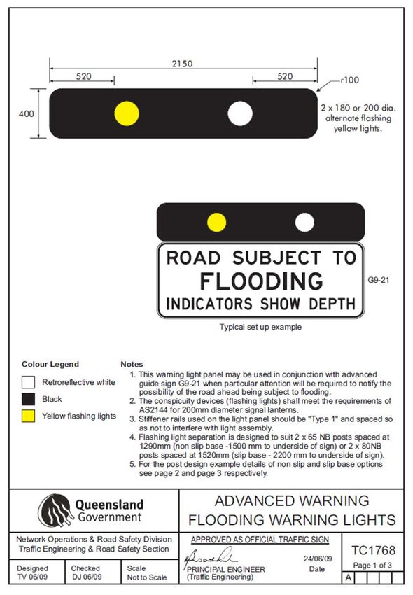
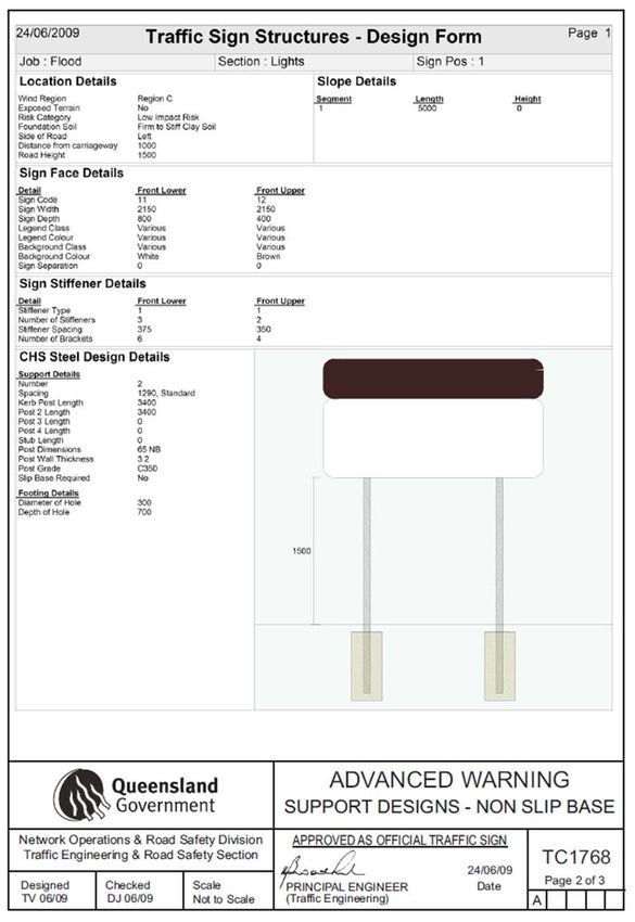
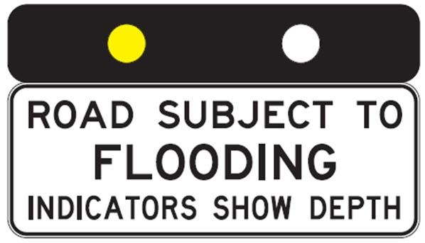
Where specified in the contract, the RFMS roadway sign face shall be as outlined in TC 1768
(Figure 9). Full drawings for TC 1768 are attached in Appendix A.
The flash rate for the flashing lights shall be configurable locally or remotely by the user, and shall
initially be set to 50/50 (lit/unlit) with a cycle time of one second.
Frangible post or slip base construction shall be used in high speed environments for mounting the
signs. The decision to use slip base or frangible posts shall be made by an engineer with the
appropriate RPEQ qualification.
Figure 9: RFMS signage showing advanced warning flooding warning lights - TC1768
10 Imaging equipment
Where specified in the contract, the provision of imaging equipment shall be as per the implementation
guidelines for internet enabled video cameras defined in the TRUM Manual.
11 Control system
The control system requirements defined in MRTS201 General Equipment Requirements apply to
equipment provided under this Technical Specification. Additional control system requirements for
equipment provided under this Technical Specification are described below.
11.1 General
For new systems unable to be integrated into STREAMS as per the Operational Requirements listed
in Clause 7, the RFMS control system shall as a minimum:
a) retrieve and communicate, automatically or on-demand, in near real-time, the flood levels and
other related system information, including images, system status and/or faults, from multiple
flood monitoring stations/sensors to STREAMS and/or a server nominated by the Principal
b) where it performs local calculations based on sensor inputs, transmit both raw data and
calculated data to STREAMS and/or a web-server nominated by the Principal
Transport and Main Roads Specifications, July 2019 7Technical Specification, MRTS233 Roadway Flood Monitoring Systems
c) activate other ITS devices such as road signage or other monitoring devices, as required
d) provide capability for both local and remote fault diagnostics, system monitoring and
configuration of the entire flood monitoring system components
e) be of a latency such that the effect of commands issued by the operator (either from
STREAMS or server nominated by the Principal), must be observed by the operator within
200 msec, and
f) be housed in an enclosure with an IP68 rating to AS60529.
11.2 STREAMS device driver
Where STREAMS device drivers do not already exist, the contractor shall engage Transmax and
provide a device driver compatible for interfacing with the STREAMS field processor meeting the
requirements of MRTS232. STREAMS currently supports weather stations capable of communicating
using a protocol which includes a “Water Level” value.
Future versions of STREAMS (STREAMS Atlas, and later versions) will utilise the inherent generic
PLC integration capability via Modbus TCP as a standard feature.
11.3 System local control
The RFMS shall allow local control via a maintenance communications port using a laptop or a
handheld device. Local control shall be gained using the diagnostic software. The system shall provide
secure access to the RFMS equipment and prevent unauthorised access to the signs.
All system diagnostics and configuration parameters able to be changed in the field shall be
accessible when the sign is selected for local control. Remote control of the RFMS shall be disabled
when the RFMS is selected for local control.
Disconnection of a laptop or handheld device shall cause the controller to revert to autonomous
operation.
Ending of the maintenance session shall not require further interaction from the user, nor in anyway
interrupt operation or require rebooting of the RFMS but immediately let the RFMS to revert to
autonomous operation.
11.4 System remote control
A remote management system must be supplied. The remote sign management software shall:
• Detail the location and current status of all RFMS sites (operational, idle, fault condition).
• Show RFMS on an interactive GUI.
• Request passwords as part of the access and configuration authorisation process.
• Implement multiple levels of user access such as:
− administrator
− maintenance
− standard user, and
− read only.
Transport and Main Roads Specifications, July 2019 8Technical Specification, MRTS233 Roadway Flood Monitoring Systems
• Allow querying of events according to set criteria such as by site, time, date, event type, or by
duration.
• Poll the RFMS in the field every 24 hours to verify the communications link and that the
system has not failed. Failure of the remote management system to gain a response from the
sign shall result in an event being logged in the system that highlights that the sign status is
unknown and possibly failed or damaged.
• Be compatible with the department’s standard operating environment Microsoft Windows®
operating system environment, Windows XP, Windows Vista, Windows 7, and those industry
standards current at the time of delivery. Any software provided shall be capable of operating
on all such operating systems, and
• Support remote connectivity to the RFMS via Satellite, 3G, 4G, GPRS, ADSL, or any
telecommunications network nominated by the Principal.
11.5 Internal clock
An internal clock shall be provided in accordance with MRTS201 General Equipment Requirements.
11.6 Communication protocol
Communication with the RFMS shall be in accordance with a protocol accepted by the Principal’s
Representative and the requirements of MRTS201.
The RFMS controller shall connect to STREAMS using the currently available generic PLC interfacing
capability, using the Modbus TCP protocol.
The current version of STREAMS uses the specific implementations of Modbus TCP to facilitate
integration of:
1. Campbell Scientific Data loggers, and
2. RMTek Data loggers.
One important advantage of this arrangement is that the STREAMS Field Processor (FP) normally
required at the RFMS site can be relocated to head end TMC’s in cases where RFMS sites are
solar powered.
12 Mechanical and physical requirements
The mechanical and physical requirements of the RFMS equipment shall be as defined in
MRTS201 General Equipment Requirements.
The enclosures used for housing any of the RFMS equipment including the controller shall be in
accordance with MRTS201 and IP rated to at least IP68 in accordance with AS 60529-2004.
Mounting structures shall be as per the requirements defined in MRTS61 Gantries and Support
Structures for Road Signs, Tolling Systems and ITS Devices. Frangible post or slip base construction
may be used in high speed environments for mounting the RFMS equipment and the signage. The
decision to use slip base or frangible posts shall be made by an Engineer with the appropriate RPEQ
qualification.
Transport and Main Roads Specifications, July 2019 9Technical Specification, MRTS233 Roadway Flood Monitoring Systems
13 Electrical requirements
13.1 Mains power
Where mains power is required, the relevant electrical requirements defined in Clause 10 of
MRTS201 General Equipment Requirements apply to this Technical Specification.
13.2 Battery power
Where mains power is required, also provide a battery power supply in accordance with Clause 10 of
MRTS201 General Equipment Requirements.
13.3 Solar power
Where solar power is specified, the requirements defined in MRTS263 Standalone Solar (PV) Power
Systems apply to this Technical Specification.
13.4 Protection against electrical transients and over-voltage
Provide protection against electrical transients and over-voltage in accordance with Clause 10 of
MRTS201 General Equipment Requirements.
14 Telecommunications requirements
The telecommunications requirements defined in MRTS201 General Equipment Requirements apply
to work under this Technical Specification. Additional requirements are as shown below.
Remote departmental RFMS sites need to communicate data within STREAMS back to Transport and
Main Roads TMC’s unless their RFMS management systems are hosted on Third party Internet sites.
In order of priority, the telecommunications backhaul links from RFMS sites to head end monitoring
sites should be implemented as listed below:
1. connection via the department’s own existing private telecommunications networks using
copper, fibre or point to point, or point to multipoint wireless systems back to the department’s
TMC’s
2. connection via the department’s default ITS network using departmental IPRT Network to
connect to the department’s TMC’s using IPRT ADSL , Next G (3G) or 4G if available, and
3. connection via Third party provided by satellite link backhaul from Third party RFMS sites
where no Telco provided mobile coverage is available.
15 Installation requirements
The sensors and associated infrastructure shall be installed at locations shown on the design
documentation. The contractor shall allow access for inspection of all mounting surfaces by the
Administrator prior to installation. Hold Point 1
After installation of the cables, the conduits shall be sealed to prevent vermin entry. Witness Point 1
16 Testing and commissioning
The testing and commissioning requirements defined in MRTS201 General Equipment Requirements
apply to work under this Technical Specification. In addition, test sheets shall demonstrate compliance
with the technical requirements of this Technical Specification prior to the delivery of the equipment to
site. Hold Point 2
Transport and Main Roads Specifications, July 2019 10Technical Specification, MRTS233 Roadway Flood Monitoring Systems
17 Documentation
The documentation requirements defined in MRTS201 General Equipment Requirements apply to
work under this Technical Specification.
Additional documentation requirements relevant to this Technical Specification are defined below.
Prior to the commencement of manufacturing works, the Contractor shall prepare and request
approval of the Principal/Administrator of three copies of the following documents:
a) fabrication and assembly drawings, detailing all of the components to be installed
b) manufacturer’s specifications of the RFMS and of all major components detailing ratings and
performance characteristics
c) a schematic layout of components, building details and interconnection diagrams
d) system operating manual
e) recommendations for routine maintenance tasks, and
f) recommendations on spare parts holdings.
Hold Point 3
The Contractor shall provide to the satisfaction of the Principal/Administrator, the following documents
prior to the delivery and acceptance of the RFMS to site:
• a statement confirming the warranty provisions associated with the RFMS and associated
equipment
• full set of installation as-constructed drawings
• compliance details of all components as required or implied under this document
• records of tests conducted by the Contractor to demonstrate compliance to this Technical
Specification, and
• project asset data in a format suitable for entry to the department’s “Queensland Asset Data
Format Version 2.0”. The department will supply relevant spreadsheet/template.
Hold Point 3
Prior to issue of Practical Completion, the Contractor shall provide a laminated A3 sized copy of the
"As Constructed" telecommunications and electrical schematics and wiring diagrams, together with all
FATs, Commissioning and Operating/Maintenance documentation, as appropriate, to the satisfaction
of the Administrator. Hold Point 3
18 Training
The training requirements defined in MRTS201 General Equipment Requirements apply to work under
this Technical Specification.
19 Maintenance
The maintenance requirements defined in MRTS201 General Equipment Requirements apply to work
under this Technical Specification.
Transport and Main Roads Specifications, July 2019 11Technical Specification, MRTS233 Roadway Flood Monitoring Systems 20 Handover The handover requirements defined in MRTS201 General Equipment Requirements apply to work under this Technical Specification. Transport and Main Roads Specifications, July 2019 12
Technical Specification, MRTS233 Roadway Flood Monitoring Systems

Appendix A

Transport and Main Roads Specifications, July 2019                  13
Technical Specification, MRTS233 Roadway Flood Monitoring Systems

Transport and Main Roads Specifications, July 2019                  14
Technical Specification, MRTS233 Roadway Flood Monitoring Systems

Transport and Main Roads Specifications, July 2019                  15
You can also read