Blast mitigation measures for stick curtain wall systems - CPNI
←
→
Page content transcription
If your browser does not render page correctly, please read the page content below
PUBLISH DATE:                                                CLASSIFICATION:
      Stick Curtain Wall Systems – Blast Mitigation                                                                                                                                            May 2021                                                     Official

                      Blast mitigation measures

                                                                                                                                                                                                                                                                    Physical Security
                      for stick curtain wall
                      systems
                      Version 1, May 2021

Disclaimer                                                                                                                 Freedom of Information Act (FOIA)
The information contained in this document is accurate as at the date it was created. It is intended as general            This information is supplied in confidence to the named reader and may not be disclosed further without prior approval from CPNI. This
guidance only and you should not rely on it. This information should be adapted for use in the specific circumstances      information is exempt from disclosure under the Freedom of Information Act 2000 (FOIA) and may be exempt under other UK information
required and you should seek specialist independent professional advice where appropriate before taking any action         legislation.
based on it. To the fullest extent permitted by law, CPNI accept no liability whatsoever for any loss or damage
incurred or arising as a result of any error or omission in the guidance or arising from any person acting, relying upon
or otherwise using the guidance. Full terms and conditions governing the use of this guidance are available on our
website at www.cpni.gov.uk.

©Crown copyright                                                                                                                                                                                                                                                                    1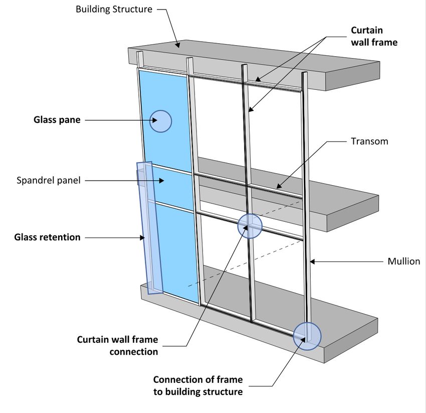
PUBLISH DATE:         CLASSIFICATION:
Stick Curtain Wall System – Blast Mitigation                              May 2021              Official

    Introduction
    Windows are extremely vulnerable to the effect of blast. Windows that have been ‘blown in or out’,
    by the blast, are likely to cause injury to people, widespread damage inside of the building, damaging
    and destroying working spaces and assets and making recovery more difficult and costly. People
    outside the building or those attempting to evacuate the building or involved in the recovery phase
    may also be vulnerable to falling glass, especially if the glass falls from upper stories of the building.

    Curtain wall systems use large panes of glass to cover the exterior of a building1. This increase in
    glazed area heightens the building’s vulnerability to a blast threat. CPNI has conducted research to
    determine effective mitigation measures to reduce the potential hazard from these systems.

    Stick curtain wall systems is one of several generic types of glass curtain walling system. A number of
    manufacturers offer these systems which are designed to comply with Building Regulations, although
    the details and overall capacity of these systems vary between manufacturers. Research has shown
    that implementing the mitigation measures outlined in this Guidance Note can significantly improve
    the blast performance of a stick curtain wall system against a VBIED threat, by reducing the standoff
    which failure occurs by half.

    CPNI would like to acknowledge the Home Office for their support in the development of this work.

    The aim of this document
    The aim of this guidance note is to provide Security Managers, Architects and Engineers with an
    understanding of the vulnerabilities of a stick curtain wall system to a blast load, the likely hazards it
    may create, and the mitigation measures that can be implemented to reduce the potential hazard.

    Technical annexes are provided at the end of this guidance note detailing the recommended
    mitigation measures.

    This guidance note should be read in conjunction with the suite of guidance notes produced by
    CPNI on the effects of blast on glass and windows. These can be found on the CPNI website. Where
    required, detailed design advice should be sought from Engineers and Specialists competent in the
    field of blast protection. Suitable Engineers and Specialists may be members of the Register of
    Security Engineers and Specialists (RSES) (www.rses.org.uk) or will be able to demonstrate that they
    have the training and experience to meet the appropriate RSES competences.
    NOTE: The façade must also comply with all other project requirements such as wind and other
    imposed loads and the appropriate building regulations.

    1
        See CPNI Guidance Note – Introduction to Glass Curtain Wall Systems

                                                                                                                  2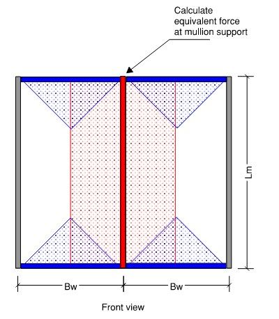
PUBLISH DATE: CLASSIFICATION:
Stick Curtain Wall System – Blast Mitigation May 2021 Official
Use and design of stick curtain wall systems
Stick curtain wall systems are one of the most common types of curtain wall systems. They are
typically utilised in shopping centres and low-rise office buildings, because they are cost effective and
versatile.
Stick curtain wall systems are designed to be connected to the edges of the floors of a framed
structure and are required to support their own self-weight i.e. a curtain wall does not form part of
the main structure of the building. Individual components are assembled on site to create the
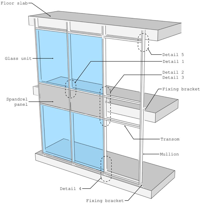
complete stick curtain wall system (Figure 1). Annex A explains the individual components of this
system, with the key elements summarised below:
- Curtain Wall Frame - The curtain wall frame is formed using hollow aluminium sections referred
to as mullions (vertical) and transoms (horizontal).
- Curtain Wall Frame Connections – Individual elements of the curtain wall frame are connected
using components that are often hidden from view. Manufacturers offer a range of connection
options and selection is normally driven by project design loads (e.g. wind loads) and appropriate
building regulations.
- Connection of Frame to the Building Structure - The mullion is connected to the edge of the
structure by a base plate. This is a flat metal plate connected to a spigot2 which is inserted into
the hollow mullion section. A similar fixing is used at each floor.
- Glass Pane – The glass pane fits inside the curtain wall frame. The glass specification will vary
depending on the project requirements and can comprise of single or double glazed units.
- Glass Retention – The glass can be retained by using a pressure plate, known as a capped system,
or by using toggles. Capped systems use external pressure plates which are screwed to the front
of the mullions and transoms to clamp the glass in position. A cover plate is then clipped over
the top of the pressure plate to hide the fixings. Toggle fixings are used to secure the glass to the
mullion and/or transom using clamps which fix either into channels within the edge seals of the
insulated glass unit (IGU) or clamp the inner glass assembly. Toggle fixings avoid clamping the
outer glass surface.
2
A spigot is a long section of aluminium which is inserted inside the hollow aluminium mullion, allowing the
frame to be connected to the structure.
3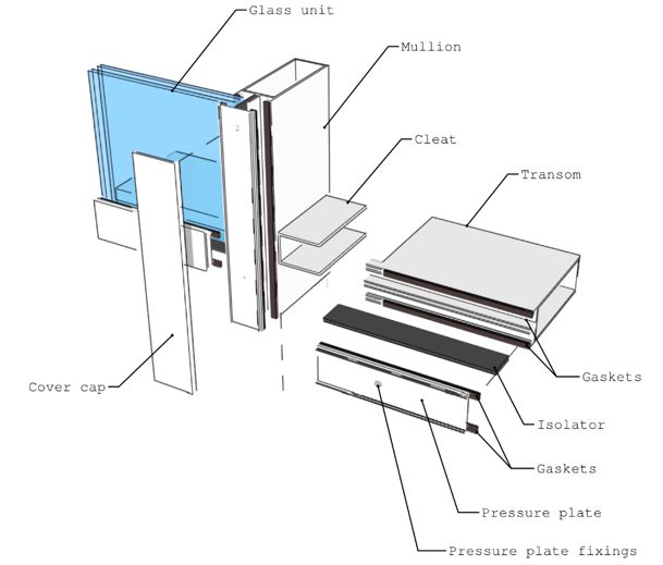
PUBLISH DATE:           CLASSIFICATION:
Stick Curtain Wall System – Blast Mitigation                           May 2021                Official

    Figure 1: Key components of a stick curtain wall system

    How do stick curtain wall systems perform against a blast load?
    Stick curtain wall systems, designed to meet conventional project requirements, are not expected to
    perform well against a blast load. The mullions and transoms are designed to create a strong frame
    to hold the glass in position against a wind load, and the glass retention systems are designed to
    retain the glass against a much smaller negative wind load.

    The performance of a stick curtain wall system will vary depending on the magnitude of the blast
    load which is dependent on the charge size and its distance from the facade. Against a VBIED threat,
    large panes of glass are likely to fall outwards, as the glass retention system doesn’t have the capacity
    to hold the glass. For a larger blast load the frame and/or connections may also fail, projecting the
    complete system inside the building, creating a much greater hazard.

    Whilst the ground floor is the most vulnerable area, it is important to note that the glazing on the
    floors above will also be subjected to the blast load and could fail in a similar manner. Large panes of
    glass typically used in these systems can weigh more than one tonne, which would be a significant
    hazard to people outside the building if it were to fall from height.

                                                                                                                 4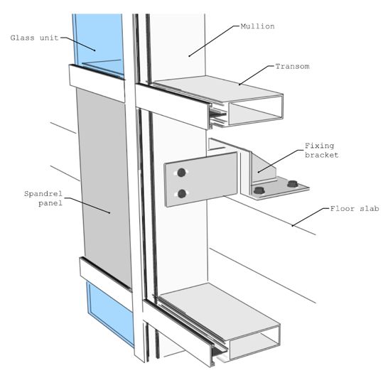
PUBLISH DATE:               CLASSIFICATION:
Stick Curtain Wall System – Blast Mitigation                                May 2021                    Official

    What measures can be used to reduce the hazard?
    There are two types of measures that can be adopted to reduce the hazards from stick curtain wall
    systems:

           •   Protection measures – complete systems that have been designed and/or tested to provide
               a specific level of protection against a defined blast load i.e. a specified charge size and
               standoff from the façade.

           •   Mitigation measures – measures that can be implemented in a system designed to meet
               conventional project requirements to reduce the hazard against a blast load.
    CPNI has conducted research to understand the performance of standard stick curtain wall systems
    against a blast load and has identified effective mitigation measures for capped stick curtain wall
    systems which address the weak elements in the system against a VBIED threat. Implementing these
    mitigation measures will achieve a balanced design with components that are broadly matched in
    strength and thus reducing the standoff which failure occurs by half that of a system designed to
    meet conventional project requirements. Based on CPNI research to date, we have found inherent
    vulnerabilities with toggle retention systems (continuous or intermitted) and have been unable to
    find a method of practically improving their performance. CPNI, therefore recommends that such
    systems are not used unless the supplier can demonstrate, with test evidence3, that they have a
    system that can significantly reduce the hazard.

    3
        Testing in accordance with CPNI Test Standard for the Explosion Resistance of Curtain Walling

                                                                                                                          5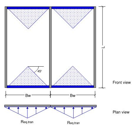
PUBLISH DATE:            CLASSIFICATION:
Stick Curtain Wall System – Blast Mitigation                                   May 2021                 Official

    Recommended CPNI mitigation measures
    The CPNI mitigation measures, for capped stick curtain wall systems, focus on five key elements of
    the façade design. All five of the recommended key elements must be implemented to achieve the
    hazard reduction.

    The five key elements are:

        1. Connection between the frame and the structure – a robust spigot section should be used
           (see Annex B and C for the design specification).
        2. Curtain wall frame – the mullion and transom section properties should meet the minimum
           requirements (as detailed in Annex B).
        3. Transom to mullion connection – a robust connection which can take inward and rebound
           loads is required (as detailed in Annex B).
        4. Glass pane – as a minimum, the innermost glass pane should be laminated glass, with a PVB
           interlayer (see Annex B for details).
        5. Glass retention – metal pressure plates with an increased number of fixings should be used
           (as detailed in Annex B). No recommendations are currently available for toggle systems.
    Technical information, for engineers and specifiers, on how to implement the five key elements of
    the mitigation measures is provided in Annex B and C.

    The specific details outlined in this guidance note should be used for stick curtain wall systems with
    approximate dimensions illustrated in Figure 2. The common approaches within this guidance note
    are also applicable to stick curtain wall systems with different frame dimensions. Detailed design
    advice should be sought from Engineers and Specialists competent in the field of blast design for
    facades that have frame dimensions greater than those specified in this guidance note.

    Figure 2: Maximum dimensions to be used with the mitigation measures stated in this guidance note

                                                                                                                          6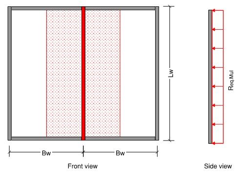
PUBLISH DATE:   CLASSIFICATION:
Stick Curtain Wall System – Blast Mitigation                                May 2021        Official

    How much will these mitigation measures cost?
    The mitigation measures in this guidance note use components that are readily available from stick
    curtain wall manufacturers. These mitigation measures could increase the façade costs by up to
    approximately 10% per square metre compared to a system designed to conventional project
    requirements only. The increase in costs is driven by the additional material cost and labour time4.

    4
        This figure is based upon a cost review study undertaken by CPNI in 2019

                                                                                                              7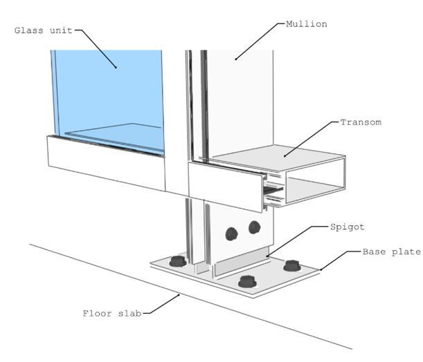
PUBLISH DATE:           CLASSIFICATION:
Stick Curtain Wall System – Blast Mitigation                         May 2021                Official

    ANNEX A – Stick curtain wall system components
    Stick curtain wall systems are produced by a number of manufacturers. The systems are unique to
    each manufacturer, but the design, fabrication and installation follow similar principles. Figures A-1
    to A-6 show typical details of a stick curtain wall systems, and Table A-1 summarises the identified
    key components.

    Figure A-1: Components of a curtain wall

                                                                                                               8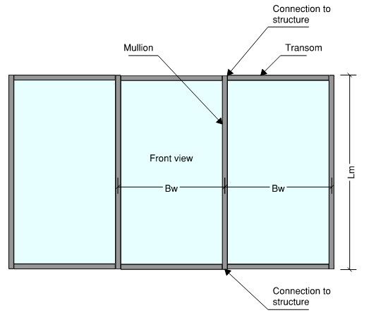
PUBLISH DATE:                CLASSIFICATION:
Stick Curtain Wall System – Blast Mitigation                                         May 2021                     Official

 Figure A-2: Detail 1 - Components of a capped stick curtain wall   Figure A-3: Detail 2 - Intermediate fixing bracket to edge of floor slab

 Figure A-4: Detail 3 – Splice connection between two mullions      Figure A-5: Detail 4 - Base plate and spigot fixing bracket

                                         Figure A-6: Detail 5 – Head plate and spigot fixing bracket

                                                                                                                                               9
PUBLISH DATE: CLASSIFICATION:
Stick Curtain Wall System – Blast Mitigation May 2021 Official
Table A-1: Summary of the key components of a stick curtain wall system
Component Description Common Terminology and Sizes
Mullions Vertical framing members of a curtain wall. The mullions Other names:
typically span between floors and are cut to length either - Sticks
in a factory for larger installations or on site for smaller - Bars
installations, e.g. a small shop front. The most common - Verticals
profile of a mullion is a hollow aluminium box. The size and
shape of the profile vary by manufacturer but are broadly Common size:
similar in design. The profiles are commonly extruded from 50mm (w) x 150mm (d)
aluminium grades EN-AW 6060-T6 and EN-AW 6060-T66.
Transoms Horizontal framing members of a curtain wall. The transom Other names:
spans between the mullions and carry the weight of the - Sticks
glass panels. Like the mullion, the most common profile of - Bars
a transom is a hollow aluminium box. The transom can be - Horizontals
cut to length either in the factory or on site depending on
the project size. Common size:
50mm (w) x 150mm (d)
Transom The mullions and transoms are mechanically connected via Other names:
connector cleat mechanical connection(s) that are blocks / profiles shaped - Button cleat / Spring cleat
to fit within the hollow cavity of a transom. - Channel cleat
- U cleat
- Shear block
- T-connection
Fixing brackets / Components designed to provide support and to transmit Other names:
Spigots the loads from the curtain wall to the building. The curtain - Base Plates
wall is connected to the structure via a fixing bracket or - Slab edge bracket
spigot is used to connect the facade to the structure. Fixing
brackets are used to connect the mullions to the edge of
the floor slab when the mullions span several floors.
Spigots are inserted inside the cavity of the mullions, either
top or bottom, and are used to connect to the floor or
soffit.
Splice The splice connection is used to connect two lengths of Other names
Connection mullion section together and is usually located close to a - Stack joint
fixing bracket. If mullions are continuous over multiple
floors the splice connection may be located at 1/4 or 1/5 of
the span height away from a support. This connection
typically consists of an extruded profile that fits within the
cavity of the two mullions and is held in position by bolts.
The connection is designed to transfer horizontal load and
may allow a small amount of vertical movement between
the two mullions due to thermal expansion.
Thermal break The thermal break provides a barrier between the external Other names:
pressure plates and the internal mullions and transoms, - isolator
minimising the heat loss through the facade system. This is
typically a flexible foam or plastic which is fitted into a
receiving channel in the front of the mullion/transom
section.
Glazing The glazing panes are installed once the grid of mullions Other names:
and transoms has been constructed. - Vision panels
- Insulated Glass Units (IGU)
10PUBLISH DATE: CLASSIFICATION:
Stick Curtain Wall System – Blast Mitigation May 2021 Official
Component Description Common Terminology and Sizes
Spandrel panel A spandrel panel is typically an opaque panel (often glass) Other names:
which is installed into the facade to hide the structural - Non-vision panels
frame i.e. in front of the edge of a concrete slab. - Infill panels
Gaskets Gaskets are preformed and profiled lengths of sealing Other names:
material installed between the inner and outer surface of - Glazing bead
the glass (or infill panel) and the surrounding frame
(mullion or transom) or pressure plate.
Pressure plates Pressure plates clamp the glass against the mullion and/or Other names:
transom. The pressure plates vary in width and are - Pressure caps
typically formed from aluminium. Holes along the
centreline of the pressure plates are often drilled or
punched in the factory for the fixings to pass through.
The pressure plates are fixed with screws driven into the
thermal break.
Cover cap Profiled external cover applied to the pressure plate to Other names:
provide an architectural finish and hide the pressure plate - Face cover
fixings.
Toggle fixings Toggle fixings offer an alternative to screw-fixed pressure Other names:
plates. The toggles are used to secure the glass to the - Toggle clamps
mullion and/or transom using clamps which fix either into - Structural glazing (but should
channels within the edge seals of the insulated glass unit not be confused with silicone
(IGU) or clamp the inner glass assembly. Toggle fixings structural glazed/bonded glass)
avoid clamping the outer glass surface.
Note: This Guidance Note is not suitable for toggle glazed
systems.
11PUBLISH DATE: CLASSIFICATION:
Stick Curtain Wall System – Blast Mitigation May 2021 Official
ANNEX B – Recommended Mitigation Measures for Capped Stick
Curtain Wall Systems (only)
This annex provides the technical information required for engineering and specifiers to
implement the recommended blast mitigation measures for stick curtain wall systems. It
does not address any other loading requirements.
Table B-1 provides a summary of the mitigation measures recommended to improve the
performance of a capped stick curtain wall systems against a blast threat. These should be considered
as the minimal requirement and all five elements must be implemented to reduce the blast hazard.
The values in Table B-1 align with readily available components for stick curtain wall systems,
meaning bespoke component should not be required. Please note, the values listed in Table B-1 are
the minimum requirements.
Table B-1: Summary of the mitigation requirements for a capped stick curtain wall system.
Component Requirement
Glazing As a minimum, the innermost ply shall be laminated glass with a 1.52 mm PVB
interlayer.
Performance of the glazing should be balanced against the performance of the
transoms, mullions and connections, i.e. it is inappropriate to use overly stiff
glass with a flexible curtain wall system as this may create an unbalanced
design and will not necessarily improve the performance.
Testing has demonstrated that the following glazing compositions provide a
balanced design when implemented with the other recommended
modifications:
Tested Glass Specification 1:
Outer Ply: 11.52 mm Heat strengthened & PVB laminated (2x5 mm plies + 1.52
mm PVB)
Cavity: Typical 16 mm (Depth not critical)
Inner Ply : 9.52 mm Heat strengthened & PVB laminated (2x4 mm plies +
1.52 mm PVB)
Tested Glass Specification 2:
Outer Ply: 6 mm Toughened
Cavity: Typical 16 mm (Depth not critical)
Inner Ply: 11.52 mm Annealed & PVB laminated (2x5 mm plies + 1.52 mm PVB)
Note: Other factors, e.g. the wind load, must also be considered when
determining the appropriate glass specification.
12PUBLISH DATE: CLASSIFICATION:
Stick Curtain Wall System – Blast Mitigation May 2021 Official
Component Requirement
Mullions As a minimum the mullions shall have section properties equal to or greater
than the following values. The values listed below are typical of a mullion
measuring approximately 50 mm wide and 150 mm deep.
A = 12 cm2 (cross-section area)
Ix = 400 cm4 (strong-axis second moment of area)
Iy = 40 cm4 (weak-axis second moment of area)
Wx = 43 cm3 (strong-axis elastic section modulus)
Wy = 17 cm3 (weak-axis elastic section modulus)
The mullion shall provide 14 mm or greater glass bite.
The mullion sections shall be extruded from aluminium grades EN-AW6060-T6
or EN-AW6060-T66, or stronger.
Transoms As a minimum the transom shall have section properties equal to or greater
than the following values. The values listed below are typical of a mullion
measuring approximately 50 mm wide and 150 mm deep.
A = 12 cm2 (cross-section area)
Ix = 295 cm4 (strong-axis second moment of area)
Iy = 40 cm4 (weak-axis second moment of area)
Wx = 36 cm3 (strong-axis elastic section modulus)
Wy = 17 cm3 (weak-axis elastic section modulus)
The transom shall provide 14 mm or greater glass bite
The transom sections shall be extruded from aluminium grades EN-AW6060-T6
or EN-AW6060-T66, or stronger.
13PUBLISH DATE: CLASSIFICATION:
Stick Curtain Wall System – Blast Mitigation May 2021 Official
Component Requirement
Spigot/Support brackets The aluminium spigot profile should fit tightly inside the mullion section
selected. As a minimum the spigot profile shall have section properties equal to
or greater than the following values:
A = 11 cm2 (cross-section area)
Wx = 35 cm3 (strong-axis elastic section modulus)
The spigot profile shall have an insertion depth of at least 250 mm into the
mullion.
The support bracket connection (i.e. a spigot connected to an endplate and
fixings to the structure), which connects the mullion to the structure, shall be
stronger than the capacity of the mullions. As a minimum requirement, the
detailed design of the connection shall be undertaken for a design load equal to
1.5x the calculated support reaction when the mullions have reached their full
plastic bending resistance under a uniformly distributed load (see Annex C for
worked example).
As a minimum the detailed design of the connections shall be checked for
vertical loads due to self-weight of the façade in combination with the
horizontal reaction force. As a minimum, two separate load cases shall be
considered.
1) Vertical loads due to self-weight + horizontal reaction acting in the
positive (inward) direction.
2) Vertical loads due to self-weight + horizontal reaction acting in the
positive (outward) direction.
It is the responsibility of the design engineer to check the connection for
additional loads that may arise as part of the specific protect detail i.e.
moments caused by eccentric loads.
For mullions spanning multiple floors, consideration shall be given to the
bending moments within the span and over intermediate supports, which will
result in a different ultimate resistance of the mullion and therefore different
support reactions.
The mullion does not require a mechanical connection to the spigot i.e. a bolt
through the spigot, when the recommended insertion depth is met.
The spigot and support brackets shall be extruded from aluminium grades EN-
AW6060-T6 or EN-AW6060-T66, or stronger.
14PUBLISH DATE: CLASSIFICATION:
Stick Curtain Wall System – Blast Mitigation May 2021 Official
Component Requirement
Splice connection The splice connection shall be located away from the area that the maximum
bending moment occurs. The designer shall ensure that yielding of the mullion
profile will occur within the main span before occurring at the splice
connection. This is typically achieved by locating the splice connection between
1/4 and 1/5 of the span height away from a support when the mullions are
continuous over multiple floors. The splice sections shall have an insertion
depth into each mullion of at least 300mm or two times the depth of the
mullion profile, whichever is greater. As a minimum the splice sections shall
have section properties equal to or greater than the following values:
A = 11 cm2 (cross-section area)
Wx = 35 cm3 (strong-axis elastic section modulus)
The splice sections shall be extruded from aluminium grades EN-AW6060-T6 or
EN-AW6060-T66, or stronger.
Mullion - transom There are several tested and approved connections. Details of these
connections connections are included in CPNIs CSE (Catalogue of Security Equipment).
The use of spring-loaded (button) cleats is not permitted.
If an alternative connection detail is required, the connection strength in the
positive and negative horizontal direction shall be proven via testing in
accordance with BS EN16758:2016. The connection strength shall be equal to
or greater than the approved connections in the CSE.
Thermal break The thread of the pressure plate fixings must breach the sides of the isolator
material and engage with the inner sides of the aluminium nose on the
mullions and transoms.
Pressure plates and Non-metallic pressure plates (e.g. plastic) are not
fixings permitted.
Capacity of the pressure plates and pull-out
capacity of the fixings that retain the glass panels
shall be equal to, or greater than 35 kN/m.
Regardless of the fixing capacity, the spacing of the
pressure plate fixings shall be no greater than 150
mm.
Cover cap Standard flat cover caps that do not project more than 25 mm from the
external surface of the glass are considered suitable. Following the initial
installation, the cover caps must be checked to ensure that they are correctly
installed and fully engaged with the pressure plate.
15PUBLISH DATE: CLASSIFICATION:
Stick Curtain Wall System – Blast Mitigation May 2021 Official
ANNEX C – Example showing how to calculate the support reaction
to be used for the detailed design of the connection between the
mullion and the structure
This worked example provides a method which can be used by an Engineer to determine a suitable
horizontal design load acting on the support between the stick curtain wall mullions and the
structure under blast conditions.
The support bracket connection, which connects the mullion to the structure, shall be designed to
be stronger than the capacity of the stick curtain wall system. The actual capacity of the stick curtain
wall system will be higher than stated within the manufacture literature. For this reason, when
considering the design of components subject to blast loading it is common practice to use the
ultimate resistance of structural elements. The ultimate resistance (plastic resistance) is the
resistance of a component above the point at which it will yield (elastic resistance).
The design of mullion and transom profiles under normal static loading is normally governed by the
deflection under wind loading. As such, it is common for manufacturers to only provide the basic
flexural properties of these profiles in their literature. The following example is based upon the
assumption that there is only basic information available about the stick curtain wall system. Where
possible the manufacturer’s information that is available should be used. Where the required
information is not available this example will provide a method to estimate the missing information.
The minimum information required to use this method is highlighted in yellow.
Vertical span between support brackets Lm = 3.6 m
Width of the bay Bw = 1.4 m
16PUBLISH DATE: CLASSIFICATION:
Stick Curtain Wall System – Blast Mitigation May 2021 Official
Width of the mullion profile w = 50 mm
mul
Depth of the mullion back- d = 150 mm
mul
box measured from rear
face to gasket
4
Second moment of area
I = 400 cm
about strong axis (x-x) of x.mul
4
mullion profile = 4,000,000 mm
Width of the transom w = 50 mm
tran
profile
Depth of the transom back- d = 150 mm
tran
box measured from rear
face to gasket
4
Second moment of area
I = 300 cm
about strong axis (x-x) of x.tran
4
transom profile = 3,000,000 mm
The aluminium alloy grade that the mullion and transom profiles are produced from may be stated
in the manufactured literature. However, if this is not stated, it is common for aluminium curtain wall
profiles to be produced from aluminium alloy grade (EN-AW 6060-T66).
2
Aluminium alloy EN-AW 6060-T66 yield stress fo = 160 N/mm
(0.2% proof stress)
Based upon observations from blast testing of stick curtain wall systems with mullion spans up to 3.6
m and bay widths up to 1.4 m wide will result in the mullions exceeding their elastic limits and all the
transoms remaining elastic, including internal transoms. As such, the capacity of the system is based
upon the plastic resistance of the mullions and the elastic resistance of the transoms.
If possible, you should obtain the values for the plastic section modulus of the mullion profile from
the manufacturer. However, if this information is not available Equation 1 can be used for an estimate
of the plastic section modulus from the value for the second moment of area and the dimensions of
the mullion profile. The factor of 1.3 has been determined from a review of mullion profiles from a
number of different manufacturers and is appropriate for calculating a conservative estimate of the
plastic modulus of a typical mullion profile.
17PUBLISH DATE: CLASSIFICATION:
Stick Curtain Wall System – Blast Mitigation May 2021 Official
Plastic section
modulus of the
mullion profile about [ EQUATION 1]
the strong axis (x-x)
If possible, you should obtain the values for the elastic section modulus of the transom profile from
the manufacturer. However, if this information is not available Equation 2 can be used for an estimate
the elastic section modulus from the value for the second moment of area and the dimensions of the
transom profile.
Elastic section
modulus of transom
profile about the [ EQUATION 2]
strong axis (x-x)
The bending resistance of the profiles are calculated using Equation 3 and 4
Plastic bending 7
resistance of the M =W f = 1.11 x 10 Nmm [ EQUATION 3]
Rd.mul pl.x.mul ( o)
mullion profile
Elastic bending 6
resistance of the MR = Wel.x.tran (fo) = 6.40 x 10 Nmm [ EQUATION 4]
d.tran
transom profile
18PUBLISH DATE: CLASSIFICATION:
Stick Curtain Wall System – Blast Mitigation May 2021 Official
The equivalent resistance of the mullions is calculated based upon the plastic bending resistance of
the profile with uniform load distribution.
Equivalent resistance
of the mullion with a
[ EQUATION 5]
rectangular loaded
area
Equation 5 is only valid for a single mullion span with pinned supports. Mullions with multiple spans
and/or different support conditions will have a different equivalent resistance which is not within the
scope of this example.
19PUBLISH DATE: CLASSIFICATION:
Stick Curtain Wall System – Blast Mitigation May 2021 Official
Transoms are not as heavily loaded as mullions and tend to remain elastic, even internal transoms
loaded by glass above and below the transom. End transoms are the same profile but loaded only on
one side, so the maximum elastic utilisation will be 50%, so the reaction should be calculated from
50% of the elastic bending capacity
Equivalent resistance
of the transom with a
[ EQUATION 6]
triangular loaded area.
20PUBLISH DATE: CLASSIFICATION:
Stick Curtain Wall System – Blast Mitigation May 2021 Official
The total equivalent force acting on the support is the sum of the resistance of the mullion (Equation
5) and the transoms (Equation 6) multiplied by their respective loaded areas. The loaded area in the
corners of each bay are counted twice but this is conservative for the calculation.
Equivalent force
acting at mullion
[ EQUATION 7]
support.
As a minimum the design of the connections shall be checked for vertical loads due to self-weight
of the stick curtain wall system in combination with the horizontal equivalent design force from
Equation 7. As a minimum, two separate load cases shall be considered.
1) Vertical loads due to self-weight +horizontal load acting in the positive (inward) direction
2) Vertical loads due to self-weight +horizontal load acting in the negative (outward) direction
21You can also read