TOYOTA SIENNA SECONDAY CONTROLS INSTALLATION GUIDE
←
→
Page content transcription
If your browser does not render page correctly, please read the page content below
TOYOTA SIENNA
                                                                        SECONDAY CONTROLS
                                                                         INSTALLATION GUIDE

                                                                                              LAST UPDATED November 8, 2018

                                                  2017© R.A.SH Tronics Ltd. All rights reserved.
Reproduction by any means, electronic, graphics (GUI) or mechanical, including photocopying, recording or by any information storage and retrieval
                 system or translation in whole or part is NOT PERMITTED without written authorization from R.A.SH Tronics Ltd.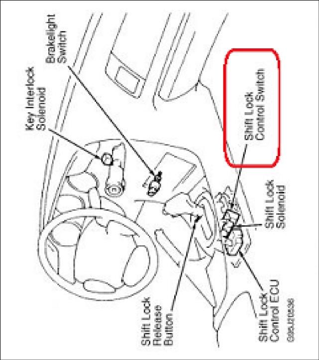
TABLE OF CONTENTS
2 ...............................................................................................................................................TABLE OF CONTENTS
3 ................................................................................................................................... TO OUR VALUED CUSTOMER
3 ....................................................................................................................................... CUSTOMER CARE CENTER
3 .............................................................................................................................................................. ABSTRACT
3 ........................................................................................................................................................ USEFUL HINTS
4 ........................................................................................................................................SYSTEM BLOCK DIAGRAM
5 ................................................................................................................................................. LIN JUNCTION BOX
5 ......................................................................................................... MRB-612L UNIVERSAL MULTY-RELAY MODULE
6 ..................................................................................................................... DESCRIPTION OF MAIN COMPONENTS
7 .................................................................................................. DESCRIPTION OF MAIN COMPONENTS CONTINUED
8 .................................................................................................................................. CAN-BUS GATEWAY MODULE
8 ........................................................................................................... FUNCTIONS CONTROLED THROUGH CAN-Bus
8 .............................................................................................................................IDENTIFYING CAN-Bus LOCATION
9 ...................................................................................................................CAN-Bus Powered gear selector module
9 ........................................................................................................ BACKGROUND ON VEHICLE SHIFT POSITIONS
10 ........................................................................................CANbus POWERED GEAR SELECTOR & GATEWAY WIRING
11 ............................................................................................................................................. ENGINE START STOP
11 ................................................................................................................................. IGNITION start STOP module
12 ............................................................................................................................... START STOP MODULE WIRING
13 .................................................................................................................................. PUSHBUTON START WIRING
14 ................................................................................................................................... MULTI-FUNCTION MODULE
15 ........................................................................................................................................ TURN SIGNALS wiring
16 ................................................................................................................................................. LIGHTS WIRING
17 ................................................................................................................................................ WIPERS WIRING
18 ............................................................................................................................. WIPERS WIRING CONTINUED
19 .................................................................................................................................................. HAZARD WIRING
20 ................................................................................................................................... CRUISE CONTROL MODULE
21 ..................................................................................................................................... POWER MIRRORS WIRING
22 ......................................................................................................................... ELECTRONIC PARK BRAKE WIRING
23 ............................................................................................................................................. VOICE SCAN WIRING
24 .................................................................................................................................................. USING THE HVAC
25 ............................................................................................................................................................ APPENDIX

                                                                                                                                                                       2
TO OUR VALUED CUSTOMER

It is our intention to provide our valued customers with the best documentation possible to ensure successful use of our
products. We will continue to improve our publications to better suit your needs. Our publications will be refined and
enhanced, as new volumes and updates introduced. If you have any questions or comments regarding this publication,
please contact us.
We welcome your feedback.

CUSTOMER CARE CENTER

For additional application assistance, we urge you to consult with our experienced staff in our Customer Care Center. Our
Technical and Engineering staff has extensive test, research and development capabilities, and have assisted many
customers in solving unique design and application problems with standard or customized products.

                  R&D Contact Address                                      US Support Contact Address

                                                                                  Clock Mobility
                                                                                 6700 Clay Ave. SW
                   R.A.SH Tronics Ltd
                                                                               Grand Rapids, MI 49548
                 rashtronix@gmail.com
                                                                                   (616) 698-9400
                                                                           technicians@clockmobility.com

ABSTRACT

This guide explains how to install the modules in the vehicle.

    v The information provided in the wiring diagrams is vehicle specific. It should be applied only to the vehicle
      indicated. Depending on the system you are installing, you may not install every harness.
    v Read modules placement first, it is very important to understand were to connect and fit the CAN-Bus based
      components to avoid future problems.
    v This manual becomes an integral part of the vehicle the system-installed in. You should therefore always keep
      it in the vehicle and pass on to the new owner, to safely use the systems.
    v R.A.SH Tronics Ltd reserve the right to make changes in product specifications at any time and without prior
      notice. The information in this manuals, believed to be accurate and reliable. However, R.A.SH Tronics Ltd
      assume no responsibility for its use.

USEFUL HINTS

         v The electronic control board is an electrostatic sensitive device. Connect to a proper ground.
         v Use care when making electrical connections. Disconnect battery power prior to servicing.
         v When installing, check for any obstructions such as Gas tank, Gas lines, Wires, etc. before drilling or routing
           power cable.
         v For continued protection against fire hazard, replace only with the same type and rating of fuse.
         v Only allow R.A.SH Tronics factory trained technicians to install or service your system. If wear is observed
           on any part in the system, contact our US support.

                                                                                                                         3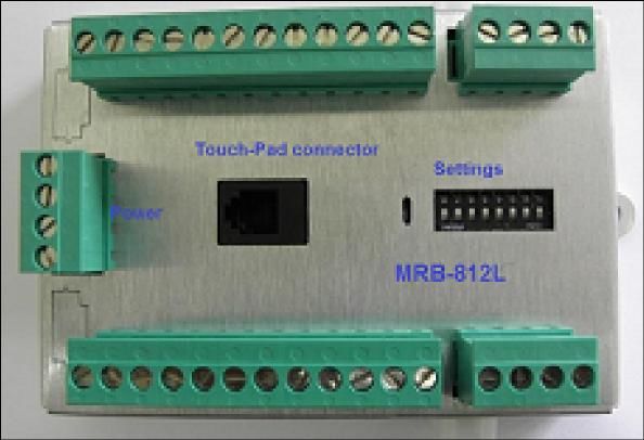
Multi -Functi on
(MRB-512L) Additional Functions
(MRB-612L)
1
4
4
1
1 6
SYSTEM BLOCK DIAGRAM
Power Mi rrors
(MRB-112L)
Crui s e Control Module (VAC-601L)
Pow er
4 7
LIN cable
LIN cable
1 1
4 1 6 1 4 1
Start/ Stop Modul e (UIS-24LL)
Pow er
LIN ca ble
4 7
LIN ca ble
1 1
4
LIN ca ble
1
CANbus Gateway Module (RSM-50-TSNA)
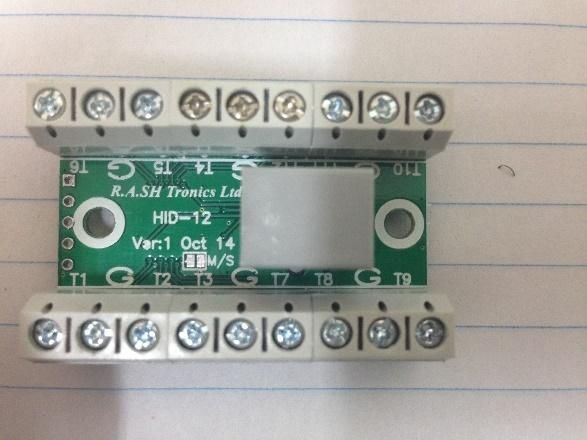
LIN junction box P/N: STA-35-LJ
Part#: IMID-1L
Ba s i c functi ons s witches Intel li gent In Moti on Voi ce Sca n Sys tem
Part#: JID-1L
Electroni c Pa rk Bra ke Module (EPB-1L) Part#: JID-2LS In moti on s ma rt functions
Sta rt/Stop
LIN cable
Gea r s el ect
Power & Spea ker
Multi -Functi on
Intelligent voice scan
module Part#: RID-1L
CANbus_1
CANbus_2
1
4
Part#: RID-2LS
IN MOTION SPEAKER
Part#: XID-6L
COMPUTER DATA
LINES SYSTEM
Input Device
Low effort switch Up to six Low effort switches
The CANbus multifunction and gear selector modules are the most critical components in the system.
They used to collect real time information about the vehicle while it is in use. the information transmitted to all modules Drivein-Touch totally integrated system, components
plugged to the junction box. Size CAGE Code DWG NO Rev
A3 059-957-746 A
© 2016 R.A.SH Tronics Ltd. All rights reserved. Reproduction by any means, electronic, graphics (GUI) or mechanical, including photocopying, recording or by any information
storage and retrieval system or translation in whole or part is NOT PERMITTED without written authorization from R.A.SH Tronics Ltd IL. Scale Sheet
1 1
4
of
LIN JUNCTION BOX
The LIN junction box a box with many connections that combines all modules.
MRB-612L UNIVERSAL MULTY-RELAY MODULE
BAT
PBSw
DSSw
GND
ON
DS1
Docking Station Mode TB2 TB3
1 2 3 4 5 6 7 8
TB1
R187a R230
LIFT UP
DOCKING
R187 Part#: MRB-612LA R287
R130 R287a
Used for sliding door Open/Close
R387a R430
LIFT DOWN
EGRESS
R387 R487
R330 R487a
R587a R630
LIFT DEPLOY LIFT STOW
ON
DS1 R587 R687
Touchpad connector
Hazard Mode 1 2 3 4 5 6 7 8
R530 R687a
R787a R830
ON
DS1
R787 R887
Lights Mode 1 2 3 4 5 6 7 8
ON R730 R887a
DS1
Wake Up relay 15min 1 2 3 4 5 6 7 8
TB4 DS1 TB5
ON Whil e gear not in Park Pos i ti on,
ON
Head/Arm rest actuator
1 2 3 4 5 6 7 8
DS1 R9_30 R10_30 Add Out Of Park Interlock backward functi on ca ncl ed,
Wake Up relay 20min Fa rward functi on onl y.
SUN VISOR
1 2 3 4 5 6 7 8
R9_87 R10_87a
ON ON DS1
DS1
R9_87a R10_87
Wake Up relay 25min 1 2 3 4 5 6 7 8 1 2 3 4 5 6 7 8
ON R11_30 Settings R12_30 Park Position Interlock
DS1 Wa ke up a cti ve ti me
Wake Up relay 30min 1 2 3 4 5 6 7 8
Programmabl e: For more i nformati on, pleas e read ma nua l.
No programma ble fea ture. R.A.SH Tronics Ltd Universal Multi-Function module, 12 high current relays
© 2018 R.A.SH Tronics Ltd. All rights reserved. Reproduction by any means, electronic, graphics (T) +972-48517656 Size CAGE Code DWG NO Rev
(GUI) or mechanical, including photocopying, recording or by any information storage and (F) +972-48523339 A4 059-957-746 Part#: MRB-612LA A
retrieval system or translation in whole or part is NOT PERMITTED without written rashtronix@gmail.com
Scale Sheet
authorization from R.A.SH Tronics Ltd IL. Thursday, August 02, 2018 SW: MRB-612L.HEX 1 of 3
5
DESCRIPTION OF MAIN COMPONENTS

DRIVEIN STA-35-xxx DISPLAY

Through this 3.5” single touch screen displays you can control all
operation and programming functions for the DRIVEIN system.
All secondary functions are also controlled and programmed
Through the display. It’s location in the vehicle will vary, depending
on the system set-up and mounting options for the driver. Most
secondary functions can be remotely operated from other devices
(In motion voice scan, five buttons Round Touchpad, five ways
joystick and do it yourself switches), depending on the customer
needs. Refer to the Drivein
Operation and Programing Manual for further details.

VEHICLE INTERFACE MODULE

Through this dual CAN-Bus gateway module, which is connected to
the vehicle communication network, it is possible to control almost
all secondary functions like Driver/passenger window, turn signals,
horn and many more. It is connected to the OBD harness and to
another CAN-Bus harness in the vehicle.
It is also used to collect real time information and update the LCD
display.

ENGINE START/STOP MODULE

This module is used to override the OEM start stop system, it is
designed to be directly attached to the OEM high current harness
using the quick-fit terminals of the OEM harness. No need to solder
just remove the OEM wires from the connector and plug them as
per wiring diagram provided in this manual for your specific vehicle.

UNIVESAL 12 RELAYS MODULE

Can do many functions:
    1. Power windows
    2. Power mirrors
    3. F/R Wipers & Washers
    4. Motor control
    5. Docking station

                                                                         6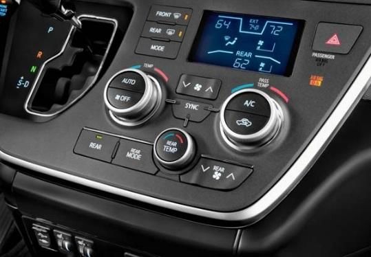
DESCRIPTION OF MAIN COMPONENTS CONTINUED

INPUT DEVICES: RID-1L round input device.

It has five buttons blue lighted with universal automotive
symbols. It should be mounted within reach of the driver.

It is designed to access the in-motion functions like turn
signals and horn.

Five big buttons easy to use, small size.

INPUT DEVICES: JID-1L joystick input device.

It is a five ways mini-joystick, very small size, easy to use
can be mounted within easy reach of the driver.

 It is designed to access the in-motion functions like turn
signals and horn.

INPUT DEVICES: DIY-1L twelve momentary switches input
device.

This module is used to access up to twelve functions in the
vehicle using low effort switches. Can be mounted under
the steering and hardwired to different switches located
within easy reach of the driver.

INPUT DEVICES: GID-1L round input device.

It has five buttons blue lighted with universal automotive
symbols. It should be mounted within reach of the driver.

It is designed to control the start stop function and gear
control.

Five big buttons easy to use, small size.

                                                                7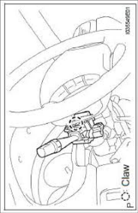
CAN-BUS GATEWAY MODULE

The R.A.SH Tronics CAN-bus gateway is a very powerful device, it allows access for many of the vehicle functions without
the need to remove plastic parts or additional external relays. The CAN gateway interface with the OEM CAN system in
order to operate most of the secondary functions.
The CAN Gateway Module connects to the Drivein LCD touch screen on the LIN
junction port and to the vehicle’s CAN system to operate the secondary functions,
listed below in the table. It is also responsible to wake up the touch screen and put
to sleep after locking the vehicle.
THESE SECONDARY FUNCTIONS WILL REQUIRE NO FURTHER PHYSICAL WIRING,
which will greatly reduce the amount of installation time and increase reliability.
There are, however, a few secondary functions that will require physical wiring.
These functions are not listed in the table below but in the pages to follow. The CAN Gateway module is connected to
the vehicle’s OBD connector located on the lower left dash panel in the driver’s area and to the low speed CAN
simultaneously. The Gateway module itself is typically installed behind the center console area and secured to vehicle
using the mounting tabs on the module. The CAN Gateway Module is responsible to wake up and put to sleep of all
system components, so be sure to connect the wires utilizing proper soldering practices according to SAE J1292.

 FUNCTIONS CONTROLED THROUGH CAN-BUS
                                           NO PHYSICAL WIRING REQUIRED
 Driver/ Passenger windows Up/Down                           HVAC (Heating ventilation and air conditioning)
 Door lock/Unlock                                               · Fans speed Up/Down/OFF
 Horn/ High beam and flash                                      · Air flow tour positions
                                                                · AC On/ Off/ Auto
 Driver/ Passenger Sliding Door Open/ Close
                                                                · SYNC
                                                                · Temp Hot/ Cold

 IDENTIFYING CAN-BUS LOCATION
              Picture A, Data Link Connector

                                                                                                                       8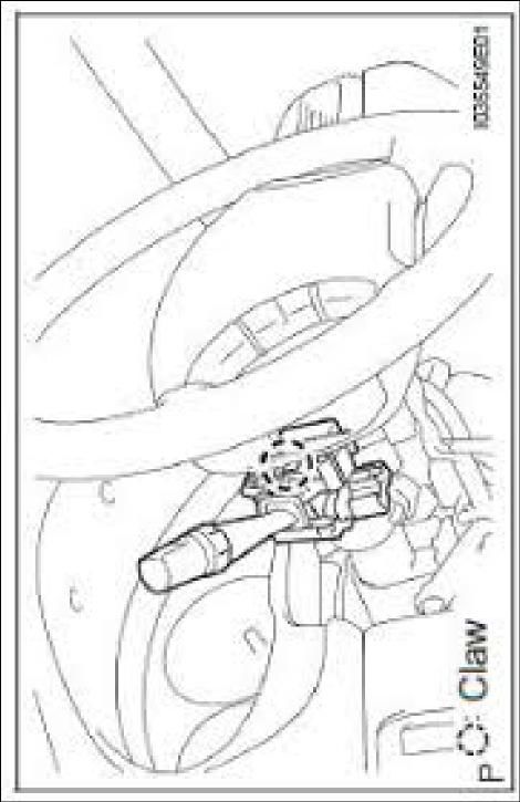
CAN-BUS POWERED GEAR SELECTOR MODULE
This new R.A.SH Electronics powered gear selector uses the CAN-Bus network information to function, it makes it easy to
fit inside any modern vehicle. Since the CAN-Bus information is very reliable, shifting do not rely on Potentiometer
position or the voltage measured out of it and do not rely on untrained programmer. Check wiring diagrams below.
This new concept of powered gear selector, brings the vehicle safety to a higher level, due to the fact that the system
collects the vehicle speed combined with the foot brake information, makes it easy to operate the system by pressing
the gear buttons shortly, not using the Long/Short press mode, once Reverse button is pressed while the vehicle is
driving in a high speed, even if the foot brake is slightly pressed, no shifting is possible. The OEM gear cable is attached
to a 52mm actuator that is linked to the controller module.
BACKGROUND ON VEHICLE SHIFT POSITIONS
What is important to understand before proceeding; is the actual mechanical position of the vehicle’s shift cable as it
moves from PARK to the lower DRIVE gears. In almost every vehicle, the PARK position is when the vehicle’s cable is
completely retracted or pushed all the way into the outer housing. You can manually cycle thru the gears by holding the
outer cable housing stationary with one hand and pulling on the eye of the cable with the other. As you pull, you will feel
the cable move approximately 9mm and stop at a detent. This is the next gear selection. So with the cable completely
retracted in the PARK position, the next detent is REVERSE, then NEUTRAL, DRIVE, D3, D2, and finally L. The number of
lower gear will vary slightly depending on the vehicle.
A
Rev
P
3
J3: Park Position Select
CAN-Bus powered gear
Part#: RSM-50-xxxx
of
R
Actuator Part#: DS1217A08 462
selector module
Powered Gear Selector Actuator Positioning
N
2
J3, Shorted
RSM-50-xxx
D
Sheet
Actuator Connector
S
Settings
J1 J2
J3 J4
Ds1
Dew to the actuator control accuracy, in some vehicles the Park position
DWG NO
needs some nudge in order to be able to remove the OEM key. Set the
Yellow(A)
059-957-746
Black(B)
Actuator connector
Yellow(A)
Black(B)
0.3Sec
J1 J2
J3 J4
Ds1
CAGE Code
0.2Sec
J1 J2
J3 J4
male
Ds1
A4
Scale
Size
0.1Sec
J1 J2
J3 J4
Ds1
RSM-50-xxxx
R.A.SH Tronics Ltd
Actuator connector
J1 Female
rashtronix@gm ail.com
Friday, August 25, 2017
J1/J2: Park position nudge.
(T) +972-48517656
(F) +972-48523339
nudging time as needed.
female
5
1
6
2
RED 1 6 AW G
7
3
IMPORTANT
8
4
BL K 1 6 AW G
J3, Open (Manufacturer default)
S
Part#: RSM-50-xxxx internal view
J3: Park Position Select
Settings
D
S w5
J1 J2
J3 J4
Ds1
S w4
N
S w3
S w2
R
S w1
P
Com
Settings
J1 J2
J3 J4
TB1
Ds1
J3: Park Position Select
Yellow(A)
Black(B)
WR-PHD_2.54mm_Jumper
Black with pullback_1x2p
Part#: 609 002 115 121
Part description
J1 J2
J3 J4
Ds1
S ettings
9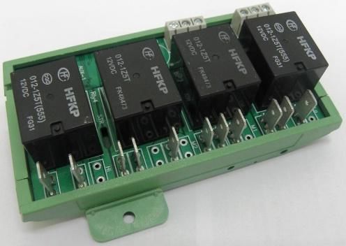
Actuator connector
fema le
Sw. Com. (-)
Sw5
Sw4
Sw3
Sw2
Sw1
Add Fuse
TB1 Front
F1 BRN or RED 16AWG (BAT)
Terminal Block
10A FUSE GND
Sw 3
BLK 16AWG (GND) Park Position
5
Sw 4
1
G204 (LEFT END OF
DASH) R/N Position
J1 Female 8 7 6 5
J1 J2 Sw 5
Pow er & CAN Input device VAC-12LCC 4 3 2 1
D Position
SUPPORTED FUNCTIONS
Sw. Com. (-)
Sw1
Sw2
Sw3
Sw4
Sw5
Left & Right sliding door
TB1
LT GRN
COMPUTER DATA
LINES SYSTEM WHT
(LEFT END OF DASH) J/D "D120" Ds1
Supported input devices
CANBUS POWERED GEAR SELECTOR & GATEWAY WIRING
RED J1 J2
COMPUTER DATA J3 J4
WHT LINES SYSTEM
Settings
ADDITIONAL SUPPORTED FUNCTIONS
Driver/ Passenger Windows
Door lock/ Unlock
Horn
High beam
HVAC
GID-1L
STA-35-xxxx DATA LINK CONNECTOR 3 J2
Input Device
(LOWER LEFT SIDE OF DASH)
A p p l i c a b l e V e h i c l e s:
TOYOTA SIENNA
R.A.SH Tronics Ltd TOYOTA SIENNA, CAN-bus powered gear selector
© 2017 R.A.SH Troni cs Ltd. All rights res erved. Reproduction by a ny means , electroni c, (T) +972-48517656 Size CAGE Code DWG NO Rev
graphics (GUI) or mechanical , including photocopying, recording or by any i nformation (F) +972-48523339 A4 059-957-746 A
RSM-50/TSA
stora ge and retrieval s ys tem or trans lation i n whole or part is NOT PERMITTED wi thout rashtronix@gmail.com
written a uthorizati on from R.A.SH Troni cs Ltd IL. Scale Sheet
Friday, June 22, 2018 SW: RSM-50-TSA.hex 2 of 3
10ENGINE START STOP
Two different engine start stop systems available for the Sienna, depending on your vehicle model, you might have a
standard rotating key for engine starting, alternatively you might find a push button start. The Drivein touch system
supports the two types using two different modules.
Check your vehicle and advise us before you place the order or before installing the
kit.
Below you find the wiring diagrams for both types.
This (UIS-24LL) start stop system is linked to the LCD touch controller, it is
constantly updated with the vehicle status through the CAN-Bus network through
powered gear selector module wired to the OBD-II. This module should be mounted in an easy to reach under the steering
area.
The systems supplied with 600mm (24”) harness, it is designed to maximize the box mounting in-between the foot brake
position switch and the engine start stop switch under the steering. So it is not recommended to extend the wire harness
of the OEM modules and the start stop system. Only one OEM cable should be cut and wired to the system harness, all
the rest are tapped into the OEM, all wires MUST be soldered, do not use any other way to tap into.
IGNITION START STOP MODULE
This (UIS-24L) start stop system is linked to the LCD touch controller, it is constantly updated with the vehicle status
through the CAN-Bus network through powered gear selector module wired to the OBD-II. This module should be
mounted in an easy to reach under the steering area.
The systems supplied with 600mm (24”) harness, it is designed to maximize the box mounting in-between the foot brake
position switch and the engine start stop switch under the steering. So it is not recommended to extend the wire harness
of the OEM modules and the start stop system. Only one OEM cable should be cut and wired to the system harness, all
the rest are tapped into the OEM, all wires MUST be soldered, do not use any other way to tap into.
Identifying 4P connector and brake pedal position switch
Park pin switch continuity chart Brake pedal position switch continuity chart
11WHT (BAT)
AM1 2
BLU (ACC/RUN)
3
YEL (IGN/RUN)
4
RED (BAT)
AM2 7
RED (START)
8
BLK (IGN)
6
IGNITION OR
JUMPER JUMPER
STARTER SWITCH
ASSEMBLY (W/O
START STOP MODULE WIRING
SMART KEY SYSTEM) F1
5A FUSE
87
87
87
30
30
30
87a
87
30
WHT/ BLK (0.5 AWG)
2
HFKP
HFKP
HFKP
HFKP
CUT ONLY IF THE KEY IS MANUALLY INSERTED
RED (0.5 AWG)
12VDC 30A
12VDC 30A
12VDC 30A
12VDC 30A
012-1Z5T(555)
012-1Z5T(555)
012-1Z5T(555)
012-1Z5T(555)
1
UNLOCK WARNING SWITCH ASSEMBLY
KEY IN/OUT
IGNITION
START
ACC
TB1 (AT IGNITION SWITCH ASSEMBLY)
R.A.SH Tronics Ltd J? OEM IGNITION SWITCH CONNECTOR
UIS-24L (AT IGNITION SWITCH ASSEMBLY)
ICSP
LIN
BAT
Park
GND
COM
IGN
Stop
Start
+12V
Neg 1
Neg 2
4 3 2 1
(UPPER LEFT SIDE 8 7 6 5
OF DASH)
Sw 1 Remove the wires from OEM
connector a nd pl ug them i n onboa rd
Sw 2 qui ck fit termi na l s .
IGN/STOP
Stand-Alone START
Option R.A.SH Tronics Ltd TOYOTA SIENNA, Start Stop wiring
(T) +972-48517656 Size CAGE Code DWG NO Rev
© 2016 R.A.SH Tronics Ltd. All ri ghts res erved. Reproduction by a ny mea ns , el ectronic, gra phics
(F) +972-48523339 A4 059-957-746 UIS-24L A
(GUI) or mecha ni ca l , including photocopying, recordi ng or by a ny i nforma tion s tora ge a nd
retrieva l s ys tem or tra ns l a ti on i n whol e or pa rt i s NOT PERMITTED wi thout wri tten a uthoriza ti on rashtronix@gmail.com
Scale Sheet
from R.A.SH Troni cs Ltd IL. Wednesday, February 14, 2018 2 of 3
12ENGINE START/STOP SWITCH, LT BLUE SS2
ON DASH, RIGHT SIDE OF 7
STEERING BLK SS1
2
WHT/ BLK (GND) SSB_GND
5
D7 (UNDER LEFT
FRONT OF CENTER
CONSOL)
WHT (BAT) POWER MANAGEMENT CONTROL
1 ECU (LOWER RIGHT END OF DASH)
BLU (BKSW)
2
VLT (IGN)
4
PUSHBUTON START WIRING
LT GRN (BKSWNC)
3
BRAKE PEDAL POSITION SWITCH
(ON BRAKE PEDAL BRACKET)
GRY
GRY
BLU
F1
ORG
BLU/ORG
WHT
WHT/BLU
BAT
(+12V) 5A FUSE
J1 6 5 4 12 11 10 9 8 7 J2
Pow er 3 2 1 6 5 4 3 2 1 Relays
BRN
BRN
Orange
G403 (LEFT CENTER
OF DASH)
Park i nterlock
Rel ay opens "OFF" whi le
in Pa rk, Clos ed while not
GRN BLK
5
Shift lever connector UIS-24LL box front view
BRN LT BLU G403 (LEFT CENTER Pow er
6
TO INTERLOCK OF DASH)
PARK PIN SWITCH J1 J2
SYSTEM 4 7
Rotary s wi tch (vehicle s pecifi c functions ) The system supports push & hold the key touch button
1 1
until engine run.
0: Univers al Start Stop
4: Honda Odyssey/ Toyota Sienna mode
R.A.SH Tronics Ltd TOYOTA SIENNA Pushbutton Start System
© 2017 R.A.SH Troni cs Ltd. All rights res erved. Reproducti on by a ny mea ns , el ectronic, (T) +972-48517656 Size CAGE Code DWG NO Rev
graphics (GUI) or mechani ca l, incl udi ng photocopying, recording or by a ny informati on (F) +972-48523339 A4 059-957-746 UIS-24LL A
s torage a nd retrieval s ys tem or trans l ati on in whole or part is NOT PERMITTED without rashtronix@gmail.com
written authorizati on from R.A.SH Tronics Ltd IL. Scale Sheet
Sunday, August 05, 2018 SW: UIS-24LL 1 of 1
13RF Input Device Input Devi ce Dip Sw itches
ON
1 2 3 4 5 6 7 8
IGN
FBK
BAT
GND
V. Type: SIENNA
TB2 TB3
TB1
R187a R230
R187 Part#: MRB-512L R287
accordingly, see picture below.
R130 R287a
MULTI-FUNCTION MODULE
R387a R430
R387 R487
R330 R487a
R587a R630
R587 R687
Touchpad connector
R530 R687a
R787a R830
R787 R887
R730 R887a
TB4 Dip Sw ? TB5
ON
R9_30 R10_30
R_87 R_87a
1 2 3 4 5 6 7 8
R_87a R_87
Settings
R11_30 R12_30
The Horn is controle d through CANbus
R.A.SH Tronics Ltd TOYOTA SIENNA Multi-Function Module
© 2017 R.A.SH Troni cs Ltd. All ri ghts re s e rved. Reproducti on by a ny mea ns , el ectroni c, (T) +972-48517656 Size CAGE Code DWG NO Rev
gra phi cs (GUI) or mecha nica l , i ncludi ng photocopying, recording or by a ny i nforma ti on (F) +972-48523339 A4 059-957-746 MRB-512L A
stora ge a nd retri eva l s ys tem or tra ns l a tion i n whole or pa rt i s NOT PERMITTED without rashtronix@gmail.com
written a uthori za ti on from R.A.SH Troni cs Ltd IL. Scale Sheet
Monday, August 06, 2018 2 of 3
relay. The turn signals canceling system is based on the steering position CANbus information, no further wiring required.
The Toyota multi-function control box is a relay based system using twelve internal relays (MRB-512L) and a small wash
The turn signals and lights control box. This box supports many vehicle types, so it is very important to set the dip switches
14FOR THE SYSTEM TO FUNCTION PROPERLY,
HEADLIGHT DIMMER THE OEM WINDSHIELD WIPER SWITCH MUST
SWITCH ASSEMBLY Add Fuse BE SET TO "AUTO" OR "OFF".
F1 IGN
5A FUSE
TURN SIGNALS WIRING
12 13 15
TURN SIGNAL SWITCH
IGN
FBK
BAT
GND
VIO (TL)
GRY (TR)
TAP INTO THE OEM WIRES (multi function switch)
WHT/BLK (GND)
Use 20AWG and as short as possible wires between OEM
and control box.
TB3
Turn signals are cancled according to steering
R230
position CANbus data.
R287
R287a
R430
R487
R487a 9 10
R630 D2 (UPPER LEFT
TB2 TB3
SIDE OF DASH)
R687 COMBINATION METER ASSEMBLY
R687a
R830
Sw # 8: OFF, Manufacturer default, steering
R887 position CANbus selected.
ON
R887a Dip Sw itches
CANbus canceling
1 2 3 4 5 6 7 8
R.A.SH Tronics Ltd TOYOTA SIENNA, Turn signals wiring
© 2017 R.A.SH Troni cs Ltd. Al l ri ghts res erved. Reproducti on by any mea ns , el ectroni c, (T) +972-48517656 Size CAGE Code DWG NO Rev
gra phi cs (GUI) or mechani cal , i ncl udi ng photocopyi ng, recordi ng or by any i nforma ti on (F) +972-48523339 A4 059-957-746 MRB-512L A
s tora ge a nd retri eva l s ys tem or trans l a ti on i n whol e or pa rt i s NOT PERMITTED wi thout rashtronix@gmail.com
wri tten a uthori za ti on from R.A.SH Troni cs Ltd IL. Scale Sheet
Monday, August 06, 2018 2 of 3
15HEADLIGHT DIMMER SWITCH ASSEMBLY
TB3
LIGHTS WIRING
R230
R287
R287a
12 20 18 11 Dip Sw itches
R430 ON
R487
1 2 3 4 5 6 7 8
YEL (Tail)
BLK (GND)
PNK (High)
R487a Vehicle Type
RED (Head)
R630 FOR THE SYSTEM TO FUNCTION PROPERLY,
THE OEM WINDSHIELD WIPER SWITCH MUST
R687 BE SET TO "AUTO" OR "OFF".
R687a TAP INTO THE OEM WIRES (multi function
switch)
R830
R887
R887a
TB3
TB5
R10_30
R10_87a
R10_87
R12_30 TB5
(UPPER LEFT SIDE
OF DASH)
R.A.SH Tronics Ltd TOYOTA SIENNA Lights wiring
© 2017 R.A.SH Troni cs Ltd. Al l rights res erved. Reproducti on by a ny mea ns , el ectronic, (T) +972-48517656 Size CAGE Code DWG NO Rev
gra phi cs (GUI) or mecha ni ca l , includi ng photocopyi ng, recording or by a ny i nforma tion (F) +972-48523339 A4 059-957-746 MRB-512L A
s tora ge a nd retrieva l s ys tem or tra ns la ti on i n whol e or pa rt i s NOT PERMITTED wi thout rashtronix@gmail.com
wri tten a uthori za tion from R.A.SH Troni cs Ltd IL. Scale Sheet
Sunday, August 05, 2018 2 of 3
16Dip Sw itches
WINDSHIELD WIPER SWITCH ASSEMBLY ON
W/Auto wiper system
1 2 3 4 5 6 7 8
TOYOTA SIENNA MODE
WIPERS WIRING
TB2
R187a
+2
+1
+B
LO
WF
EW
WR
R187
2 7 5 3 4 3 2
R130
PNK
GRY
FOR THE SYSTEM TO FUNCTION PROPERLY, THE
HOT WITH
IGN
VIO
PNK
GRY
R387a OEM WINDSHIELD WIPER SWITCH MUST BE SET TO
(D25) BRN
"AUTO" OR "OFF".
WHT/BLK
R387
TAP INTO THE OEM WIRES (multi
R330 function switch)
(UPPER LEFT SIDE OF
DASH) R587a
TB2 TB3
R587
R530 TB1
R787a
R787
R730
TB4
R9_30
R9_87 TB4 TB5
R9_87a
R11_30
WINDSHIELD WIPER RELAY ASSEMBLY (UPPER LEFT SIDE
(LOWER RIGHT END OF DASH) OF DASH)
R.A.SH Tronics Ltd TOYOTA SIENNA Front wipers wiring, W/Auto wiper system
(T) +972-48517656 Size CAGE Code DWG NO Rev
© 2017 R.A.SH Tronics Ltd. Al l rights res erved. Reproducti on by a ny mea ns , el ectroni c, gra phics
(F) +972-48523339 A4 059-957-746 MRB-512L A
(GUI) or mecha ni ca l , incl udi ng photocopying, recordi ng or by a ny informa ti on s tora ge a nd
retri eva l s ys tem or tra ns la ti on in whole or pa rt i s NOT PERMITTED wi thout wri tten rashtronix@gmail.com
Scale Sheet
a uthori za ti on from R.A.SH Troni cs Ltd IL. Monday, August 06, 2018 1 of 1
17FOR THE SYSTEM TO FUNCTION PROPERLY,
WINDSHIELD WIPER SWITCH ASSEMBLY THE OEM WINDSHIELD WIPER SWITCH MUST
W/Auto Wiper System BE SET TO "AUTO" OR "OFF".
HOT WITH
IGN
+1
+2
+B
LO
WF
EW
WR
2 5 3 3 4 7 2
PNK
TB2
PNK
GRY
R187a
(D25) BRN
(D23) BLK
GRY
WHT/BLK
R187
WIPERS WIRING CONTINUED
R130
R387a
TAP INTO THE OEM WIRES (multi
R387
function switch)
R330 Must use 16AWG and as short as
possible wires between OEM and
R587a control box.
R587
TB2 TB1 TB3
R530
R787a
R787
R730
TB4
R9_30
R9_87
Dip Sw itches R9_87a
ON
WINDSHIELD WIPER RELAY ASSEMBLY (UPPER LEFT SIDE R11_30 TB4 TB5
(LOWER RIGHT END OF DASH) 1 2 3 4 5 6 7 8 OF DASH)
TOYOTA SIENNA MODE
R.A.SH Tronics Ltd TOYOTA SIENNA Front wipers wiring, W/O Auto wiper system
(T) +972-48517656 Size CAGE Code DWG NO Rev
© 2017 R.A.SH Troni cs Ltd. Al l rights res erved. Reproducti on by a ny mea ns , el ectroni c, gra phi cs
(F) +972-48523339 A4 059-957-746 MRB-512L A
(GUI) or mecha nica l, i ncl udi ng photocopyi ng, recordi ng or by a ny i nforma ti on s tora ge a nd
retri eva l s ys tem or tra ns l a ti on in whol e or pa rt i s NOT PERMITTED without wri tten rashtronix@gmail.com
Scale Sheet
a uthori za ti on from R.A.SH Troni cs Ltd IL. Monday, August 06, 2018 1 of 1
18TB2 TB3
A/C CONTROL ASSEMBLY
MRB-612L module
HAZARD SWITCH
TB2
HAZARD WIRING
6 5 R187a
BLK
R187
R130
R387a
WHT/BLK (GND)
R387
R330
R587a
R587
R530
R787a
5
D3 (RIGHT KICK R787
TAP INTO THE OEM WIRES (multi function switch) PANEL)
Use 20AWG and as short as possible wires between OEM R730
and control box. COMBINATION METER ASSEMBLY
R.A.SH Tronics Ltd TOYOTA SIENNA, Hazard Wiring
© 2017 R.A.SH Troni cs Ltd. Al l ri ghts res erved. Reproducti on by a ny means , el ectroni c, graphi cs (T) +972-48517656 Size CAGE Code DWG NO Rev
(GUI) or mecha nical , i ncl udi ng photocopyi ng, recordi ng or by any i nforma ti on s tora ge and (F) +972-48523339 A4 059-957-746 A
MRB-612L
retri eval s ys tem or tra ns l a ti on i n whol e or pa rt i s NOT PERMITTED wi thout wri tten a uthori za tion rashtronix@gmail.com
from R.A.SH Troni cs Ltd IL. Scale Sheet
Sunday, August 05, 2018 2 of 3
19VAC-601L, Box front view
Pow er
J1 J2
4 7
1 1
SPIRAL CABLE SUB-ASSEMBLY (TOP OF
2 1 STEERING COLUMN)
TO ECM (LEFT SIDE OF
"CRUISE ACCELERATE"
"CRUISE SET/DECELERATE"
Default: +12V
"CRUISE ON"
BLK (18) ENGINE COMPARTMENT)
CRUISE CONTROL MODULE
3.2V 6.4V 0.2V
BRN (GND)
R2
220R R1
640R
BLU
WHT
F1
BLU/ORG
RD (20GA)
WHT/BLU
IGN 5A
Pow er 6 5 4 12 11 10 9 8 7 Relays
BRN (30)
BRN (87)
J1 3 2 1 6 5 4 3 2 1 J2
4
1
B1 (LEFT REAR OF
ENGINE) LIN junction box P/N: STA-35-LJ
Set Di p Swi tch to pos i ti on #4
R.A.SH Tronics Ltd TOYOTA SIENNA CRUISE CONTROL MODULE
(T) +972-48517656 Size CAGE Code DWG NO Rev
© 2018 R.A.SH Troni cs Ltd. Al l ri ghts res erved. Reproducti on by a ny means , el ectroni c, gra phi cs (F) +972-48523339 A4 059-957-746 VAC-601L A
(GUI) or mecha ni ca l , i ncl udi ng photocopyi ng, recordi ng or by a ny i nforma ti on s torage and
rashtronix@gmail.com
retri eva l s ys tem or tra ns l ati on i n whol e or pa rt i s NOT PERMITTED wi thout wri tten authori za ti on Scale Sheet
Tuesday, August 14, 2018 1 of 1
from R.A.SH Troni cs Ltd IL.
20MV LT BLU (DRV L/R) #10
MH YEL (DRV U/D) #9
MV RED (PASS L/R) #12
MH BLU (PASS U/D) #11
TO RIGHT EXTERIOUR MIRROR #4 LY GRN (COM) #13
TO LEFT EXTERIOUR MIRROR #4
(Ri ght/Down:Pos )
TB2 TB3 WHT/BLK (GND) #15 OUTER MIRROR
POWER MIRRORS WIRING
(Left/Up:Neg) SWITCH ASSEMBLY
R187a R230 PNK or BRN (IGN) #7
Check yours el f R187 R287
DRV PAS
PC U/D
DC COM
U D L R U D L R R130 R287a
R230 N P N P P N N P
R387a R430
R330 P N N P N P N P
F1
R430 N P N P N P N N R387 R487
5A
PC L/R
DC U/D
R530 N P P N N P N P
R330 R487a
Us er i nterfa ce touch buttons R587a R630
R587 R687
BAT
GND
DC L/R
R530 R687a TB2 TB1 TB3
TB1
R787a R830
R787 R887
R730 R887a
DS U/P/L/R
TB4 TB5
R9_30 R10_30
TB4 TB5
R9_87 R12_87a
IMPORTANT NOTES
R9_87a R12_87 1)All wires colors i n thi s di a gra m a re for a dvi s ory onl y, you ma y
us e otherwi s e.
© 2017 R.A.SH Tronics Ltd. Al l rights res erved. Reproduction R11_30 R12_30 2) Us e 20AWG wi res .
by a ny mea ns , el ectroni c, gra phi cs (GUI) or mecha ni ca l , The MRB-112L mus t be mounted ins i de the dri ver door.
i ncl udi ng photocopyi ng, recordi ng or by a ny i nforma tion
s tora ge a nd retri eva l s ys tem or tra ns l a ti on i n whol e or TOYOTA SIENNA, EXTERIOUR MIRRORS WIRING
pa rt i s NOT PERMITTED wi thout written a uthori za ti on from
R.A.SH Troni cs Ltd IL.
Part#: MRB-112L Date: 08-Nov-18
21RED (16AWG) ORG (16AWG)
Connect using BLK (16AWG)
0.24" Quick Fit GND
Terminals RED (16AWG)
BLK (16AWG) BRN (16AWG) BAT (Add 15A
Automotive Fuse)
J1 Female? 8 7 6 5
OEM/ Pow er 4 3 2 1
ELECTRONIC PARK BRAKE WIRING
Internal terminal blocks
IDENTIFYING THE PARK BRAKE SWITCH
Note:
Sw5
Sw4
Sw3
Sw2
Sw1
Com. (-)
TB1 Front?
The Park Brake Indication is a relay.
Terminal Block
The relay can pass Positive or Negative up to 5A.
GND
GND
GRY (30) LIN junction box P/N: STA-35-LJ
SW1
87a
30 BRAKE ON/OFF
87
Optional
INTERNAL RELAY
GRY (87A)
(BASE OF PARKING BRAKE PEDAL
ASSEMBLY) PARKING BRAKE SWITCH
Park brake symbols on touch screen
5
4
1
1
J1
Pow er/CAN connector LIN ca ble
Ins ert i n a ny a va i l a bl e connector
Key Fatures:
Press and Hold to apply/ Release the brake.
Minimum w iring.
While the vehicle in move, the park brake sw itch is immediately apply and release.
No Ignition sw itch dependent. R.A.SH Tronics Ltd Universal Powered Park Brake System (E-STOPP Actuator)
(T) +972-48517656 Size CAGE Code DWG NO Rev
© 2017 R.A.SH Troni cs Ltd. Al l rights res erved. Reproducti on by a ny mea ns , el ectroni c, gra phi cs (F) +972-48523339 A4 059-957-746 PB-1LC A
(GUI) or mecha ni ca l , includi ng photocopyi ng, recordi ng or by a ny i nforma ti on s tora ge a nd
rashtronix@gmail.com
retri eva l s ys tem or tra ns l a tion in whol e or pa rt i s NOT PERMITTED wi thout wri tten a uthori za ti on Scale Sheet
Tuesday, November 21, 2017 SW: PB-1LC.hex 2 of 3
from R.A.SH Troni cs Ltd IL.
22In Motion box P/N: IMID-1L
LCD connector
VOICE SCAN WIRING
1
4
Volume increase
4
Volume decrease
Extended function
1 select
Extended function select
Short press: Play music
Volume decrease
Five ways joystick
DIY Sw itch
Green (20AWG) Sw itch
Volume increase
F1 SW PUSHBUTTON
Green (20AWG) Com.
RED RED (20AWG)
J1-6 BAT/ IGN
The switch is not supplyed. Add
The red wire can be powered by 5A FUSE momentary switch if not used with
BAT or switch supply IGN. 6 5 4 J1 Female the Joystick.
3 2 1
Pow er
BLACK (20AWG)
J1-3 GND
SPEAKER (-)
Speaker supplyed as part of the system.
So no need to add spearer.
SPEAKER (+)
R.A.SH Tronics Ltd IN MOTION, INTELLIGENT VOICE SCAN SYSTEM
© 2017 R.A.SH Tronics Ltd. All rights reserved. Reproduction by any means, electronic, (T) +972-48517656 Size CAGE Code DWG NO Rev
graphics (GUI) or mechanical, including photocopying, recording or by any information (F) +972-48523339 A4 059-957-746 IMID-1L A
storage and retrieval system or translation in whole or part is NOT PERMITTED without rashtronix@gmail.com
Scale Sheet
written authorization from R.A.SH Tronics Ltd IL. Wednesday, September 20, 2017 1 of 1
23USING THE HVAC
The HVAC module is very smart, it can control almost all funtions of the driver side only. Some touch buttons can do
two or more functions, please read the instructions and practice yourself before driving.
This is the multifunction control touch button: press repeadetdly to toggle through the
settings and manually choose one of the following air distribution modes (Panel, Floor,
Panel and Floor,Floor and Defrost).
Press and Hold this button to select the SYNC mode, this mode is used to select singel or
dual zone.
This touch button can do three functions:
Shortly press to decreas the fan speed one step.
Press and hold to constantly decrease the fan speed until button released. If the button
continue to be depressed for more than 2 seconds, the HVAC will be turned off.
Shortly press this touch button to turn on the HVAC and increase the fan speed one step.
Press and hold to constantly increase the fan speed until the button released of the
maximm speed reached.
Shortly press this touch button to toggle the AC “Air conditioning” on or off.
Press and hold to engage full automatic operation
Shortly press this touch button increase (Hot) the tempereture one step.
Press and hold to constantly increase the temperature until the button released or the
maximm temperature reached.
Shortly press this touch button decrease (Cold) the tempereture one step.
Press and hold to constantly decrease the temperature until the button released or the
maximm temperature reached.
24APPENDIX
SPECIFICATIONS
The following chart lists the standard wire colors and their corresponding abbreviations that will be used for the
installation of all R.A.SH Tronics Ltd products.
WIRE COLOR COLOR ABBREVIATION WIRE GAUGES CURRENT RATING
BLACK BLK 0.3mm AWG22 5A
BROWN BRN 0.5mm AWG20 7A- 13A
RED RED 0.85 mm AWG18 9A-17A
ORANGE ORG 1.28 mm AWG16 12A-22A
YELLOW YEL 2 mm AWG14 16A-30A
VIOLET VLT 3 mm AWG12 21A-40A
GRAY GRY
WHITE WHT
TAN TAN
PINK PNK
PURPLE PPL
BLUE BLU
LIGHT BLUE LT BLU
DARK BLUE DK BLU
GREEN GRN
LIGHT GREEN LT GRN
DARG GREEN DK GRN
SOLDERING SPECIFICATION
Soldering Method- The soldering method shown at
right is offered for general information. Depending on
the connection desired, other methods may be used.
25You can also read